![]() User Manual
User Manual
SenseFace 4 Series
Date: March 2024
Doc Version: 1.0
Thank you for choosing our product. Please read the instructions carefully before operation. Follow these instructions to ensure that the product is functioning properly. The images shown in this manual are for illustrative purposes only.
![]() For further details, please visit our Company’s website www.zkteco.com.
For further details, please visit our Company’s website www.zkteco.com.
Copyright © 2024 ZKTECO CO., LTD. All rights reserved.
Without the prior written consent of ZKTeco, no portion of this manual can be copied or forwarded in any way or form. All parts of this manual belong to ZKTeco and its subsidiaries (hereinafter the “Company” or “ZKTeco”).
Trademarkz![]() is a registered trademark of ZKTeco. Other trademarks involved in this manual are owned by their respective owners.
is a registered trademark of ZKTeco. Other trademarks involved in this manual are owned by their respective owners.
Disclaimer
This manual contains information on the operation and maintenance of the ZKTeco equipment. The copyright in all the documents, drawings, etc. in relation to the ZKTeco supplied equipment vests in and is the property of ZKTeco. The contents hereof should not be used or shared by the receiver with any third party without express written permission of ZKTeco.
The contents of this manual must be read as a whole before starting the operation and maintenance of the supplied equipment. If any of the content(s) of the manual seems unclear or incomplete, please contact ZKTeco before starting the operation and maintenance of the said equipment. It is an essential pre-requisite for the satisfactory operation and maintenance that the operating and maintenance personnel are fully familiar with the design and that the said personnel have received thorough training in operating and maintaining the machine/unit/equipment. It is further essential for the safe operation of the machine/unit/equipment that personnel has read, understood and followed the safety instructions contained in the manual.
In case of any conflict between terms and conditions of this manual and the contract specifications, drawings, instruction sheets or any other contract-related documents, the contract conditions/documents shall prevail. The contract specific conditions/documents shall apply in priority. ZKTeco offers no warranty, guarantee or representation regarding the completeness of any information contained in this manual or any of the amendments made thereto. ZKTeco does not extend the warranty of any kind, including, without limitation, any warranty of design, merchantability or fitness for a particular purpose.
ZKTeco does not assume responsibility for any errors or omissions in the information or documents which are referenced by or linked to this manual. The entire risk as to the results and performance obtained from using the information is assumed by the user. ZKTeco in no event shall be liable to the user or any third party for any incidental, consequential, indirect, special, or exemplary damages, including, without limitation, loss of business, loss of profits, business interruption, loss of business information or any pecuniary loss, arising out of, in connection with, or relating to the use of the information contained in or referenced by this manual, even if ZKTeco has been advised of the possibility of such damages.
This manual and the information contained therein may include technical, other inaccuracies or typographical errors. ZKTeco periodically changes the information herein which will be incorporated into new additions/amendments to the manual. ZKTeco reserves the right to add, delete, amend or modify the information contained in the manual from time to time in the form of circulars, letters, notes, etc. for better operation and safety of the machine/unit/equipment. The said additions or amendments are meant for improvement /better operations of the machine/unit/equipment and such amendments shall not give any right to claim any compensation or damages under any circumstances. ZKTeco shall in no way be responsible (i) in case the machine/unit/equipment malfunctions due to any non-compliance of the instructions contained in this manual (ii) in case of operation of the machine/unit/equipment beyond the rate limits (iii) in case of operation of the machine and equipment in conditions different from the prescribed conditions of the manual. The product will be updated from time to time without prior notice. The latest operation procedures and relevant documents are available on http://www.zkteco.com. If there is any issue related to the product, please contact us.
ZKTeco Headquarters
Address ZKTeco Industrial Park, No. 32, Industrial Road,
Tangxia Town, Dongguan, China.
Phone +86 769 – 82109991
Fax +86 755 – 89602394
For business related queries, please write to us at: sales@zkteco.com.
To know more about our global branches, visit www.zkteco.com.
About the Company
ZKTeco is one of the world’s largest manufacturer of RFID and Biometric (Fingerprint, Facial, Finger-vein) readers. Product offerings include Access Control readers and panels, Near & Far-range Facial Recognition Cameras, Elevator/floor access controllers, Turnstiles, License Plate Recognition (LPR) gate controllers and Consumer products including battery-operated fingerprint and face template-reader Door Locks. Our security solutions are multi-lingual and localized in over 18 different languages. At the ZKTeco state-of-the-art 700,000 square foot ISO9001-certified manufacturing facility, we control manufacturing, product design, component assembly, and logistics/shipping, all under one roof. The founders of ZKTeco have been determined for independent research and development of biometric verification procedures and the productization of biometric verification SDK, which was initially widely applied in PC security and identity authentication fields. With the continuous enhancement of the development and plenty of market applications, the team has gradually constructed an identity authentication ecosystem and smart security ecosystem, which are based on biometric verification techniques. With years of experience in the industrialization of biometric verifications, ZKTeco was officially established in 2007 and now has been one of the lobally leading enterprises in the biometric verification industry owning various patents and being selected as the National High-tech Enterprise for 6 consecutive years. Its products are protected by intellectualproperty rights.
About the Manual
This manual introduces the operations of SenseFace 4 Series.
All figures displayed are for illustration purposes only. Figures in this manual may not be exactly consistent with the actual products.
Features and parameters with ★ are not available in all devices.
Document Conventions
Conventions used in this manual are listed below:
GUI Conventions
| For Software | |
| Convention | Description |
| Bold font | Used to identify software interface template names e.g. OK, Confirm, Cancel. |
| > | Multi-level menus are separated by these brackets. For example, File > Create > Folder. |
| For Device | |
| Convention | Description |
| < > | Button or key names for devices. For example, press <OK>. |
| [ ] | Window names, menu items, data table, and field names are inside square brackets. For example, pop up the [New User] window. |
| / | Multi-level menus are separated by forwarding slashes. For example, File/Create/Folder. |
Symbols
| Convention | Description |
| This represents a note that needs to pay more attention to. | |
| The general information which helps in performing the operations faster. | |
| The information which is significant. | |
| Care taken to avoid danger or mistakes. | |
| The statement or event that warns of something or that serves as a cautionary example. |
Data Security Statement
ZKTeco, as a smart product supplier, may also need to know and collect some of your personal information to better assist you in using ZKTeco’s goods and services, and will treat your privacy carefully by developing a Privacy Policy.
Please read and understand completely all the privacy protection policy regulations and key points that appear on the device before using ZKTeco products.
As a product user, you must comply with applicable laws and regulations related to personal data protection when collecting, storing, and using personal data, including but not limited to taking protective measures for personal data, such as performing reasonable rights management for devices, strengthening the physical security of device application scenarios, and so on.
Safety Measures
The following precautions are to keep the user’s safety and prevent any damage. Please read carefully before installation.
- Read, follow, and retain instructions – All safety and operational instructions must be properly read and followed before bringing the device into service.
- Do not ignore warnings – Adhere to all warnings on the unit and in the operating instructions.
- Accessories – Use only manufacturer-recommended or product-sold accessories. Please do not use any other components other than manufacturer suggested materials.
- Precautions for the installation – Do not place this device on an unstable stand or frame. It may fall and cause serious injury to persons and damage to the device.
- Service – Do not try to service this unit yourself. Opening or removing covers may expose you to hazardous voltages or other hazards.
- Damage requiring service – Disconnect the system from the main AC or DC power source and refer service personnel under the following conditions:
When cord or connection control is affected.
When the liquid was spilled, or an item dropped into the system.
If the system is exposed to water and/or inclement weather conditions (rain, snow, and more).
If the system is not operating normally under operating instructions.
Just change controls defined in operating instructions. Improper adjustment of other controls may result in damage and involve a qualified technician to return the device to normal operation. - Replacement parts – When replacement parts are required, service technicians must only use replacement parts provided by the supplier. Unauthorized substitutes can lead to the risk of burns, electric shock, or other hazards.
- Safety check – On completion of service or repair work on the unit, ask the service technician to perform safety checks to ensure proper operation of the unit.
- Power sources – Operate the system only from the label’s power source form. If the sort of power supply to use is unclear, call your dealer.
- Lightning – Can install external lightning conductors to protect against electrical storms. It stops power-ups destroying the system.
The devices should be installed in areas with limited access.
Instruction for Use
Before getting into the Device features and functions, it is recommended to be familiar with the below fundamentals.
Finger Positioning
Recommended fingers: The index, middle, or ring fingers are recommended fingers to use, and avoid using the thumb or pinky, as they are difficult to position correctly onto the fingerprint reader.

Note: Please use the correct method when pressing your fingers onto the fingerprint reader for registration and identification. Our company will assume no liability for recognition issues that may result from incorrect usage of the product. We reserve the right of final interpretation and modification concerning this point.
1.2 Standing Position, Posture and Facial Expression
- The recommended distance
 The distance between the device and a user whose height is in a range of 1.55 m to 1.85 m is recommended to be 0.3 m to 1.7 m. Users may slightly move forward or backward to improve the quality of facial images captured.
 - Recommended standing posture and facial expression

Note: During enrollment and verification, please remain natural facial expression and standing posture.
1.3 Face Template Registration
Please make sure that the face template in the centre of the screen during registration. Please face towards the camera and stay still during face template registration. The screen should look like the image below:

Correct face template registration and authentication method
- Recommendation for Registering a Face Template
When registering a face template, maintain a distance of 40 cm to 80 cm space between the device and the face template. - Be careful not to change your facial expression. (Smiling face template, drawn face template, wink, etc.)
- If you do not follow the instructions on the screen, the face template registration may take longer or may fail.
- Be careful not to cover the eyes or eyebrows.
- Do not wear hats, masks, sunglasses, or eyeglasses.
- Be careful not to display two face templates on the screen. Register one person at a time.
- It is recommended for a user wearing glasses to register both face templates with and without glasses.
Recommendation for Authenticating a Face Template
- Ensure that the face template appears inside the guideline displayed on the screen of the device.
- If the glasses have been changed, authentication may fail. If the face template without glasses has been registered, authenticate the face template without glasses further. If the face template with glasses has been registered, authenticate the face template with the previously worn glasses.
- If a part of the face template is covered with a hat, a mask, an eye patch, or sunglasses, authentication may fail. Do not cover the face template, allow the device to recognize both the eyebrows and the face template.
1.4 Standby Interface
After connecting the power supply, the following standby interface template is displayed:

- Click
 icon to enter the User ID input interface template.
 - When there is no Super Administrator set in the device, tap icon to go to the menu.
- After setting the Super Administrator on the device, it requires the Super Administrator’s verification before entering the menu functions.
Note: For the security of the device, it is recommended to register super administrator the first time you use the device. - On the standby interface template, the punch state options can also be shown and used directly. Click anywhere on the screen apart from the icons, and six shortcut keys appears on the screen, as shown in the figure below:

- Press the corresponding punch state key to select your current punch state, which is displayed in green.
Note: The punch state options are off by default and need to be changed to other option in the “7.4 Punch States Options” to get the punch state options on the standby screen.
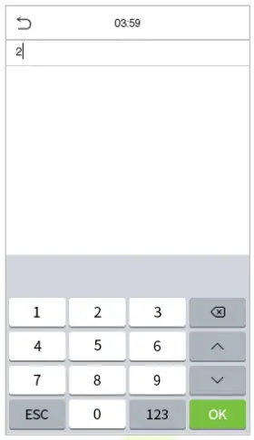
1.5 Virtual Keyboard

Note:
The device supports the input in Chinese language, English language, numbers, and symbols.
- Click EN to switch to the English keyboard.
- Press 123 to switch to the numeric and symbolic keyboard.
- Click ABC to return to the alphabetic keyboard.
- Click the input box, virtual keyboard appears.
- Click ESC to exit the virtual keyboard.
1.6 Verification Mode
1.6.1 Fingerprint Verification
Note: This function is only for SenseFace 4A.
- 1: N Fingerprint Verification Mode
The device compares the current fingerprint with the available fingerprint data stored in its database.
Fingerprint authentication mode is activated when a user places their finger onto the fingerprint scanner.
Please follow the recommended way to place your finger onto the sensor. For details, please refer to section Finger Positioning.
- 1: 1 Fingerprint Verification Mode
The device compares the current fingerprint with the fingerprints linked to the entered User ID through the virtual keyboard
In case users are unable to gain access using the 1:N authentication method, they can attempt to verify their identity using the 1:1 verification mode.
Click ![]() the button on the main screen to enter 1:1 fingerprint verification mode.
the button on the main screen to enter 1:1 fingerprint verification mode.
Input the user ID and press OK.
If the user has registered face template and password in addition to his/her fingerprints and the verification method is set to password/fingerprint/face template verification, the following screen will appear. Select the fingerprint icon to![]() enter fingerprint verification mode.
enter fingerprint verification mode.

Press the fingerprint to verify.

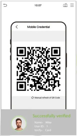
1.6.2 QR Code Verification
Note: This function is only for SenseFace 4C.
In this verification mode, the device compares the QR code image collected by the QR code collector with all the QR code data in the device.
Tap Mobile Credential on the ZKBioAccess Mobile Page, and a QR code will appear, which includes employee ID and card number (static QR code only includes card number) information. The QR code can replace a physical card on a specific device to achieve contactless authentication. Please refer to
15.4 Mobile Credential.
 2#5Tf/5XrDtZ0TNwSywY2UAamPtS8nqgw+rmdA0vrya/s=
1.6.3 Card Verification
- 1:N card verification
The 1:N card verification mode compares the card number in the card induction area with all the card number data registered in the device; The following screen displays on the card verification:
- 1:1 card verification
The 1:1 card verification mode compares the card number in the card induction area with the number associated with the employee’s User ID registered in the device.
Pressin the main interface template to open the 1:1 card verification mode.
Enter the user ID and click OK.

If the user has registered face template, card and password in addition to his/her card, and the verification method is set to fingerprint/card/password verification, the following screen will appear.
Select the icon![]() to enter the card verification mode.
to enter the card verification mode.

After successful verification, the prompt box displays “Successfully Verified”, as shown below:

1.6.4 Facial Verification
- 1:N Facial Verification
device compares the currently acquired facial images with all the registered face template data stored in its database. The following is the pop-up prompt box displaying the result of the comparison.
- 1:1 Facial Verification
In this verification mode, the device compares the face template captured by the camera with the facial template related to the entered user ID. Press icon in the main interface template and enter the
1:1 facial verification mode and enter the user ID and click OK.

If the user has registered card and password in addition to his/her face template, and the verification method is set to face template/fingerprint/password verification, the following screen will appear.
Select the icon![]() to enter the face template verification mode.
to enter the face template verification mode.

After successful verification, the prompt box displays “Successfully Verified”, as shown below:

If the verification is failed, it prompts “Person not registered”.
1.6.5 Password Verification
The device compares the entered password with the registered password by the given User ID.
Click the ![]() button on the main screen to enter the 1:1 password verification mode. Then, input the user ID and press OK.
button on the main screen to enter the 1:1 password verification mode. Then, input the user ID and press OK.

If the user has registered face template and card in addition to password, and the verification method is set to face template/fingerprint/password verification, the following screen will appear. Select the ![]() icon to enter password verification mode.
icon to enter password verification mode.

Input the password and press OK.

The following screen displays, after inputting a correct password and a wrong password respectively.

1.6.6 Combined Verification
To increase security, this device offers the option of using multiple forms of verification methods. A total of 12 different verification combinations can be used, as shown below:
Combined Verification Symbol Definition:
| Symbol | Definition | Explanation |
| / | or | This method compares the entered verification of a person with the related verification template previously stored to that Personnel ID in the Device. |
| + | and | This method compares the entered verification of a person with all the verification template previously stored to that Personnel ID in the Device. |

Procedure to set for Combined Verification Mode:
- Combined verification requires personnel to register all the different verification method. Otherwise, employees will not be able to successfully verify the combined verification process.
- For instance, when an employee has registered only the data, but the Device verification mode is set as “Face + Password”, the employee will not be able to complete the verification process successfully.
- This is because the Device compares the scanned face template template of the person with registered verification template (both the Face template and the Password) previously stored to that Personnel ID in the Device.
- But as the employee has registered only the Face template but not the Password, the verification will not get completed and the Device displays “Verification Failed”.
Press ![]() on the Standby interface to enter the Main Menu, the following screen will be displayed:
on the Standby interface to enter the Main Menu, the following screen will be displayed: 
Function Description
| Menu | Descriptions |
| User Mgt. | To add, edit, view, and delete basic information of a User. |
| User Role | To set the permission scope of the custom role and enroller for the users, that is, the rights to operate the system. |
| COMM. | To set the relevant parameters of network, serial comm, pc connection, wireless network, cloud server, wiegand and network diagnosis. |
| System | To set the parameters related to the system, including date time, access logs setting, face template & fingerprint parameters★, video intercom parameters, security setting, update firmware online, USB upgrade, and reset to factory. |
| Personalize | This includes user interface, voice, bell schedules, punch state options and shortcut key mappings settings. |
| Data Mgt. | To delete all relevant data in the device. |
| Intercom | To set the parameters related to the SIP and NVR. |
| Access Control | To set the parameters of the lock and the relevant access control device including options like time rule, holiday settings, combine verification, anti- passback setup, and duress option settings. |
| USB Manager | To upload or download the specific data by a USB drive. |
| Attendance Search | To query the specified event logs, check attendance photos and blocklist attendance photos. |
| Autotest | To automatically test whether each module functions properly, including the LCD screen, audio, microphone, camera, fingerprint sensor★ and real-time clock. |
| System Info | To view data capacity, device and firmware information and privacy policy of the device. |
Note: When users use the product for the first time, they should operate it after setting administrator privileges. Tap User Mgt. to add an administrator or edit user permissions as a super administrator. If the product does not have an administrator setting, the system will show an administrator setting command prompt every time you enter the device menu.

User Management
3.1 User Registration
Click User Mgt. on the main menu.

3.1.1 User ID and Name
Tap New User. Enter the User ID and Name.

Notes:
- A username can contain a maximum of 34 characters.
- The user ID may contain 1 to 14 digits by default.
- During the initial registration, you can modify your ID, which cannot be modified after registration.
- If a message “Duplicated!” pops up, you must choose another ID as the enter User ID already exists.
3.1.2 User Role
On the New User interface, tap on User Role to set the role for the user as either Normal User or Super Admin.
- Super Admin: The Super Administrator owns all management privileges in the Device.
- Normal User: If the Super Admin is already registered in the Device, then the Normal Users will not have the privileges to manage the system and can only access authentication verifications.
- User Defined Roles: The Normal User can also be set with User Defined Role which are the custom roles that can be set to the Normal User.

Note: If the selected user role is the Super Admin, the user must pass the identity authentication to access the main menu. The authentication is based on the authentication method(s) that the super administrator has registered. Please refer to 1.6 Verification Mode.
3.1.3 Fingerprint★
Click Fingerprint to enter the fingerprint registration page. Select the finger to be enrolled.

Press the same finger on the fingerprint reader three times. Green indicates that the fingerprint was enrolled successfully.

3.1.4 Face Template
Tap Face in the New User interface to enter the face template registration page.
- Please face towards the camera and position your face template inside the white guiding box and stay still during face template registration.
- A progress bar shows up while registering the face template and a “Enrolled Successfully” is displayed as the progress bar completes.
- If the face template is registered already then, the “Duplicate Face” message shows up. The registration interface is as follows:

3.1.5 Card
Tap Card in the New User interface to enter the card registration page.
- On the Card interface, swiping card underneath the card reading area. The card registration will be successful.
- If the card is registered already then, the “Duplicate Card” message shows up. The registration interface is as follows:

3.1.6 Password
Tap Password in the New User interface to enter the password registration page.
- On the Password interface, enter the required password and re-enter to confirm it and tap OK.
- If the re-entered password is different from the initially entered password, then the device prompts the message as “Password not match!”, where the user needs to re-confirm the password again.

Note: The password may contain 6 to 8 digits by default.
3.1.7 Profile Photo
Tap on Profile Photo in the New User interface to go to the Profile Photo registration page.

- When a user registered with a photo passes the authentication, the registered photo will be displayed.
- Tap Profile Photo, the device’s camera will open, then tap the camera icon to take a photo. The captured photo is displayed on the top left corner of the screen and the camera opens again to take a new photo, after taking the initial photo.
Note: While registering a face template, the system automatically captures a photo as the user profile photo.
If you do not register a profile photo, the system automatically sets the photo captured while registration as the default photo.
3.1.8 Access Control Role
The Access Control Role sets the door access privilege for each user. This includes the access group, duress fingerprint and facilitates to set the group access time-period.
- Tap Access Control Role > Access Group, to assign the registered users to different groups for better management. New users belong to Group 1 by default and can be reassigned to other groups. The device supports up to 99 Access Control groups.
- Tap Time Period, to select the time period to use.

Search for Users
On the Main Menu, tap User Mgt., and then tap All Users to search for a User.
- On the All Users interface, tap on the search bar on the user’s list to enter the required retrieval keyword (where the keyword may be the user ID, surname or full name) and the system will search for the related user information.

3.3 Edit User
On All Users interface, tap on the required user from the list and tap Edit to edit the user information.

3.4 Delete User
On All Users interface, tap on the required user from the list and tap Delete to delete the user or a specific user information from the device. On the Delete interface, tap on the required operation and then tap OK to confirm the deletion.
- Delete operations:
Delete User: All information of the user will be deleted (deletes the selected User as a whole) from the Device.
Delete Fingerprint Only: Deletes the fingerprint information of the selected user.
Delete Face Only: Deletes the face template information of the selected user.
Delete Password Only: Deletes the password information of the selected user.
Delete Card Number Only: Deletes the card information of the selected user.
Delete Profile Photo Only: Deletes the profile photo of the selected user.

3.5 Display Style
Tap on User Mgt. > Display Style to choose the style of All Users interface’s list.

Different display styles are shown as below:

User Role
User Role facilitates to assign some specific permissions to specific users, based on the requirement.
- On the Main menu, tap User Role, and then tap on the User Defined Role to set the user defined permissions.
- The permission scope of the custom role can be set up to 3 roles, that is, the custom operating scope of the menu functions of the user.

- On the User Defined Role interface, toggle Enable Defined Role to enable or disable the user defined role.
- Tap on Name and enter the custom name of the role.

- Then, tap on User Defined Role and select the required privileges to assign to the new role, and then tap on the Return button.
- During privilege assignment, the main menu function names will be displayed on the left and its sub-menus will be listed on its right.
- First tap on the required Main Menu function name, and then select its required sub-menus from the list.

Note: If the User Role is enabled for the Device, tap on User Mgt. > New User > User Role to assign the created roles to the required users. But if there is no super administrator registered in the Device, then the device will prompt “Please enroll super admin first!” when enabling the User Role function.
Communication Settings
Tap COMM. on the Main Menu to set the relevant parameters of Network, Serial Comm, PC Connection, Wireless Network, Cloud Server, Wiegand and Network Diagnosis.

5.1 Network Settings
When the device needs to communicate with a PC over the Ethernet, you need to configure network settings and ensure that the device and the PC are connecting to the same network segment.
Tap Ethernet on the Comm. Settings interface to configure the settings.

Function Description
| Function Name | Descriptions |
| Display in Status Bar | Toggle to set whether to display the network icon on the status bar. |
| IP Address | The default IP address is 192.168.1.201. It can be modified according to the network availability. |
| Subnet Mask | The default Subnet Mask is 255.255.255.0. It can be modified according to the network availability. |
| Gateway | The default Gateway address is 0.0.0.0. It can be modified according to the network availability. |
| DNS | The default DNS address is 0.0.0.0. It can be modified according to the network availability. |
| DHCP | Dynamic Host Configuration Protocol is to dynamically allocate IP addresses for clients via server. |
5.2 Serial Comm
Serial Comm function facilitates to establish communication with the device through a serial port (RS485/ Master Unit).
Tap Serial Comm. on the Comm. Settings interface.

Function Description
| Function Name | Descriptions |
| Serial Port | no using: Do not communicate with the device through the serial port. RS485(PC): Communicates with the device through RS485 serial port. Master Unit: When RS485 is used as the function of “Master unit”, the device will act as a master unit, and it can be connected to RS485 card reader. |
| Baud Rate | The rate at which the data is communicated with PC, there are 4 options of baud rate: 115200 (default), 57600, 38400, and 19200.The higher is the baud rate, the faster is the communication speed, but also the less reliable. Hence, a higher baud rate can be used when the communication distance is short; when the communication distance is long, choosing a lower baud rate would be more reliable. |
5.3 PC Connection
To improve the security of data, please set a Comm Key for communication between the device and the PC. The connection password needs to be entered before the device can be connected to the PC software if a Comm Key is set.
Tap PC Connection on the Comm. Settings interface to configure the communication settings.

Function Description
| Function Name | Descriptions |
| Comm Key | The default password is 0 and can be changed. The Comm Key must be 6 digits. |
| Device ID | Identity number of the device, which ranges between 1 and 254. If the communication method is RS232/RS485, you need to input this device ID in the software communication interface. |
| TCP COMM. Port | The default TCP COMM Port value is 4370. It can be modified according to the network availability. |
| HTTPS | To increase the security of software access, users can enable the HTTPS protocol to create a secure and encrypted network transmission and assure the security of sent data through identity authentication and encrypted communication. This function is enabled by default. This function can be enabled or disabled through the menu interface, and when changing the HTTPS status, the device will pop up a security prompt, and restart after confirmation. |
5.4 Wireless Network★
The device provides a Wi-Fi module, which can be built-in within the device mould or can be externally connected.
The Wi-Fi module enables data transmission via Wi-Fi (Wireless Fidelity) and establishes a wireless network environment. Wi-Fi is enabled by default in the device. If you don’t need to use the Wi-Fi network, you can toggle the Wi-Fi to disable button.
Tap Wireless Network on the Comm. Settings interface to configure the WiFi settings.

- Search the WIFI Network
- WIFI is enabled in the Device by default. Toggle on
 button to enable or disable WIFI.
 - Once the Wi-Fi is turned on, the device will search for the available WIFI within the network range.
- Choose the appropriate WiFi name from the available list, and input the correct password in the password interface, and then tap Connect to WIFI (OK).

WIFI Enabled: Tap on the required network from the searched network list.
Tap on the password field to enter the password, and then tap on Connect to WIFI (OK).
- When the WIFI is connected successfully, the initial interface will display the Wi-Fi logo.
- Add WIFI Network Manually
The Wi-Fi can also be added manually if the required Wi-Fi does not show on the list.

Tap on Add WIFI Network to add the WIFI manually.
On this interface template, enter the WIFI network parameters. (The added network must exist.)
Note: After successfully adding the WIFI manually, follow the same process to search for the added WIFI name. Click here to view the process to search the WIFI network.
- Advanced Setting
On the Wireless Network interface, tap on Advanced to set the relevant parameters as required.

Function Description
| Function Name | Description |
| DHCP | Dynamic Host Configuration Protocol (DHCP) dynamically allocates IP addresses to network clients. If the DHCP is enabled, then the IP cannot be set manually. |
| IP Address | IP address for the WIFI network, the default is 0.0.0.0. It can be modified according to the network availability. |
| Subnet Mask | The default Subnet Mask of the WIFI network is 255.255.255.0. It can be modified according to the network availability. |
| Gateway | The default Gateway address is 0.0.0.0. Can be modified according to the network availability. |
| DNS | The default DNS address is 0.0.0.0. It can be modified according to the network availability. |
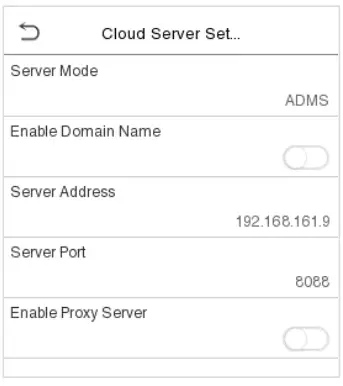
5.5 Cloud Server Setting
Tap Cloud Server Setting on the Comm. Settings interface to connect with the ADMS server.
Function Description
| Function Name | Description | |
| Enable Domain Name | Server Address | Once this function is enabled, the domain name mode “http://…” will be used, such as http://www.XYZ.com, while “XYZ” denotes the domain name (when this mode is turned ON). |
| Disable Domain Name | Server Address | IP address of the ADMS server. |
| Server Port | Port used by the ADMS server. | |
| Enable Proxy Server | When you choose to enable the proxy, you need to set the IP address and port number of the proxy server. | |
5.6 Wiegand Setup
To set the Wiegand input and output parameters.
Tap Wiegand Setup on the Comm. Settings interface to set the Wiegand input or output parameters.
Note: The Wiegand interface is shared, and the user can choose to use either the Wiegand input or Wiegand output function to interface with different Wiegand devices.

5.6.1 Wiegand Input
Tap ID Type on the Wiegand Setup, select Wiegand Input, and then tap Wiegand Options on the Wiegand Setup.

Function Description
| Function Name | Descriptions |
| Wiegand Format | Values range from 26 Bits, 32 Bits, 34 Bits, 36 Bits, 37 Bits, 50 Bits and 64Bits. |
| Wiegand Bits | Number of bits of Wiegand data. |
| Pulse Width(us) | The value of the pulse width sent by Wiegand is 100 microseconds by default, which can be adjusted within the range of 20 to 400 microseconds. |
| Pulse Interval(us) | The default value is 1000 microseconds, which can be adjusted within the range of 200 to 20000 microseconds. |
| ID Type | Select between User ID and card number. |
Various Common Wiegand Format Description
| Wiegand Format | Description |
| Wiegand26 | ECCCCCCCCCCCCCCCCCCCCCCCCO Consists of 26 bits of binary code. The 1st bit is the even parity bit of the 2nd to 13th bits, while the 26th bit is the odd parity bit of the 14th to 25th bits. The 2nd to 25th bits is the card numbers. |
| Wiegand26a | ESSSSSSSSCCCCCCCCCCCCCCCCO Consists of 26 bits of binary code. The 1st bit is the even parity bit of the 2nd to 13th bits, while the 26th bit is the odd parity bit of the 14th to 25th bits. The 2nd to 9th bits is the site codes, while the 10th to 25th bits are the card numbers. |
| Wiegand34 | ECCCCCCCCCCCCCCCCCCCCCCCCCCCCCCCCO Consists of 34 bits of binary code. The 1st bit is the even parity bit of the 2nd to 17th bits, while the 34th bit is the odd parity bit of the 18th to 33rd bits. The 2nd to 25th bits is the card numbers. |
| Wiegand34a | ESSSSSSSSCCCCCCCCCCCCCCCCCCCCCCCCO Consists of 34 bits of binary code. The 1st bit is the even parity bit of the 2nd to 17th bits, while the 34th bit is the odd parity bit of the 18th to 33rd bits. The 2nd to 9th bits is the site codes, while the 10th to 25th bits are the card numbers. |
| Wiegand36 | OFFFFFFFFFFFFFFFFCCCCCCCCCCCCCCCCMME Consists of 36 bits of binary code. The 1st bit is the odd parity bit of the 2nd to 18th bits, while the 36th bit is the even parity bit of the 19th to 35th bits. The 2nd to 17th bits is the device codes. The 18th to 33rd bits is the card numbers, and the 34th to 35th bits are the manufacturer codes. |
| Wiegand36a | EFFFFFFFFFFFFFFFFFFCCCCCCCCCCCCCCCCO Consists of 36 bits of binary code. The 1st bit is the even parity bit of the 2nd to 18th bits, while the 36th bit is the odd parity bit of the 19th to 35th bits. The 2nd to 19th bits is the device codes, and the 20th to 35th bits are the card numbers. |
| Wiegand37 | OMMMMSSSSSSSSSSSSCCCCCCCCCCCCCCCCCCCE Consists of 37 bits of binary code. The 1st bit is the odd parity bit of the 2nd to 18th bits, while the 37th bit is the even parity bit of the 19th to 36th bits. The 2nd to 4th bits is the manufacturer codes. The 5th to 16th bits is the site codes, and the 21st to 36th bits are the card numbers. |
| Wiegand37a | EMMMFFFFFFFFFFSSSSSSCCCCCCCCCCCCCCCCO Consists of 37 bits of binary code. The 1st bit is the even parity bit of the 2nd to 18th bits, while the 37th bit is the odd parity bit of the 19th to 36th bits. The 2nd to 4th bits is the manufacturer codes. The 5th to 14th bits is the device codes, and15th to 20th bits are the site codes, and the 21st to 36th bits are the card numbers. |
| Wiegand50 | ESSSSSSSSSSSSSSSSCCCCCCCCCCCCCCCCCCCCCCCCCCCCCCCCO Consists of 50 bits of binary code. The 1st bit is the even parity bit of the 2nd to 25th bits, while the 50th bit is the odd parity bit of the 26th to 49th bits. The 2nd to 17th bits is the site codes, and the 18th to 49th bits are the card numbers. |
“C“ denotes the card number; “E” denotes the even parity bit; “O” denotes the odd parity bit; “F“ denotes the facility code; “M” denotes the manufacturer code; “P” denotes the parity bit; and “S” denotes the site code.
5.6.2 Wiegand Output
Tap ID Type on the Wiegand Setup, select Wiegand Output, and then tap Wiegand Options on the Wiegand Setup.

Function Description
| Function Name | Descriptions |
| SRB★ | When SRB is enabled, the lock is controlled by the SRB to prevent the lock from being opened due to device removal. |
| Wiegand Format | Values range from 26 bits, 32 Bits, 34 bits, 36 bits, 37 bits, and 50 bits. |
| Wiegand Output Bits | After selecting the required Wiegand format, select the corresponding output bit digits of the Wiegand format. |
| Failed ID | If the verification is failed, the system will send the failed ID to the device and replace the card number or personnel ID with the new one. |
| Site Code | It is similar to the device ID. The difference is that a site code can be set manually, and is repeatable in a different device. The valid value ranges from 0 to 256 by default. |
| Pulse Width(us) | The time width represents the changes of the quantity of electric charge with regular high-frequency capacitance within a specified time. |
| Pulse Interval(us) | The time interval between pulses. |
| ID Type | Select the ID types as either User ID or card number. |
5.7 Network Diagnosis
To set the network diagnosis parameters.
Tap Network Diagnosis on the Comm. Settings interface to set the IP address diagnostic and start the diagnostic parameters.

System Settings
Set related system parameters to optimize the performance of the device.
Tap System on the Main Menu interface to set the related system parameters to optimize the performance of the device.

6.1 Date and Time
Tap Date Time on the System interface to set the date and time.

- The product supports the NTP synchronization time system by default. This function takes effect after NTP Server is enabled and the corresponding NTP server address link is set.
- If users need to set date and time manually, disable NTP Server first, and then tap Manual Data and Time to set date and time and tap Confirm to save.

- Tap 24-Hour Time to enable or disable this format. If enabled, then select the Date Format to set the date format.
- Tap Daylight Saving Time to enable or disable the function. If enabled, tap Daylight Saving Mode to select a daylight-saving mode and then tap Daylight Saving Setup to set the switch time.

- When restoring the factory settings, the time (24-hour) and date format (YYYY-MM-DD) can be restored, but the device date and time cannot be restored.
Note: For example, the user sets the time of the device (18:35 on March 15, 2019) to 18:30 on January 1, 2020.
After restoring the factory settings, the time of the equipment will remain 18:30 on January 1, 2020.
6.2 Access Logs Settings
Click Access Logs Settings on the System interface. 
Function Description
| Function Name | Description |
| Camera Mode | This function is disabled by default. When enabled, a security prompt will pop-up and the sound of shutter in the camera will turn on mandatorily. There are 5 modes: No Photo: No photo is taken during user verification. Take photo, no save: Photo is taken but is not saved during verification. Take photo and save: Photo is taken and saved during verification. Save on successful verification: Photo is taken and saved for each successful verification. Save on failed verification: Photo will be taken and saved only for each failed verification. |
| Display User Photo | This function is disabled by default. When enabled, there will be a security prompt. |
| Alphanumeric User ID | Decides whether to support letters in a User ID. |
| Access Logs Alert | When the record space of the attendance access reaches the maximum threshold value, the device will automatically display the memory space warning. Users may disable the function or set a valid value between 1 and 9999. |
| Periodic Del of Access Logs | When access records have reached full capacity, the device will automatically delete a set of old access records. Users may disable the function or set a valid value between 1 and 999. |
| Periodic Del of T&A Photo | When attendance photos have reached full capacity, the device will automatically delete a set of old attendance photos. Users may disable the function or set a valid value between 1 and 99. |
| Periodic Del of Blocklist Photo | When block listed photos have reached full capacity, the device will automatically delete a set of old block listed photos. Users may disable the function or set a valid value between 1 and 99. |
| Authentication Timeout(s) | The time length of the message of successful verification displays. Valid value: 1~9 seconds. |
| Recognition Interval (s) | To set the facial template matching time interval as required. Valid value: 0~9 seconds. |
6.3 Face Template Parameters
Tap Face on the System interface to go to the face template parameter settings.

| FRR | FAR | Recommended matching thresholds | |
| 1:N | 1:1 | ||
| High | Low | 45 | 25 |
| Medium | Medium | 35 | 15 |
| Low | High | 25 | 10 |
Function Description
| Function Name | Description |
| 1:N Threshold | Under 1:N verification mode, the verification will only be successful when the similarity between the acquired facial image and all registered facial templates is greater than the set value. The valid value ranges from 0 to 100. The higher the thresholds, the lower the misjudgement rate, the higher the rejection rate, and vice versa. It is recommended to set the default value of 75. |
| 1:1 Threshold | Under 1:1 verification mode, the verification will only be successful when the similarity between the acquired facial image and the user’s facial templates enrolled in the device is greater than the set value. The valid value ranges from 0 to 100. The higher the thresholds, the lower the misjudgement rate, the higher the rejection rate, and vice versa. It is recommended to set the default value of 63. |
| Face Enrollment Threshold | During face template enrollment, 1:N comparison is used to determine whether the user has already registered before. When the similarity between the acquired facial image and all registered facial templates is greater than this threshold, it indicates that the face template has already been registered. |
| Image Quality | Image quality for facial registration and comparison. The higher the value, the clearer the image requires. |
| Facial Recognition Distance | Face template recognition of the maximum distance, greater than this value will be filtered. The parameter value can be understood as the face template size required for registration and comparison. The farther the distance from people, the smaller the face template pixels obtained by the algorithm. When the value is 0, it means that the face template comparison distance is not limited. |
| Live Detection | Detecting the spoof attempt using visible light images to determine if the provided biometric source sample is really a person (a live human being) or false representation. |
| Binocular Live Detection Threshold | It is convenient to judge whether the near-infrared spectral imaging is fake photo and video. The larger the value, the better the anti-spoofing performance of near-infrared spectral imaging. |
| WDR | Wide Dynamic Range (WDR) balances light and extends image visibility for surveillance videos under high contrast lighting scenes and improves object identification under bright and dark environments. |
| Anti-flicker Mode | Used when WDR is turned off. This helps reduce flicker when the device’s screen flashes at the same frequency as the light. |
| Face Algorithm | Facial algorithm related information and pause facial template update. |
| Notes | Improper adjustment of the exposure and quality parameters may severely affect the performance of the device. Please adjust the exposure parameter only under the guidance of the after-sales service personnel of our company. |
6.4 Fingerprint Parameters★
Click Fingerprint on the System interface.

| FRR | FAR | Recommended matching thresholds | |
| 1:N | 1:1 | ||
| High | Low | 45 | 25 |
| Medium | Medium | 35 | 15 |
| Low | High | 25 | 10 |
Function Description
| Function Name | Descriptions |
| 1:1 Threshold | Under 1:1 verification method, the verification will only be successful when the similarity between the acquired fingerprint data and the fingerprint template associated with the entered user ID enrolled in the device is greater than the set value. |
| 1:N Threshold | Under 1:N verification method, the verification will only be successful when the similarity between the acquired fingerprint data and the fingerprint templates enrolled in the device is greater than the set value. |
| FP Sensor Sensitivity | To set the sensibility of fingerprint acquisition. It is recommended to use the default level “Medium”. When the environment is dry, resulting in slow fingerprint detection, you can set the level to “High” to raise the sensibility; when the environment is humid, making it hard to identify the fingerprint, you can set the level to “Low”. |
| 1:1 Retry Attempts | In 1:1 Verification, users might forget the registered fingerprint, or press the finger improperly. To reduce the process of re-entering user ID, retry is allowed. |
| Fingerprint Algorithm | Fingerprint algorithm version. Default support ZKFinger VX13.0, can change to ZKFinger VX10.0. |
| Fingerprint Image | This function is disabled by default. After disabling it, the fingerprint image will not be displayed when registering and verifying fingerprints. The menu interface allows to enable or disable this function, and there are security prompts when switching. Four choices are available: Show for enroll: to display the fingerprint image on the screen only during enrollment. Show for match: to display the fingerprint image on the screen only during verification. Always show: to display the fingerprint image on screen during enrollment and verification. None: not to display the fingerprint image. |
6.5 Device Type Setting
Tap Device Type Setting on the System interface.

Function Description
| Function Name | Description |
| Communication Protocol | Set the device communication protocol. (BEST protocol is managed by ZKBio Zlink, please refer to 15 Connecting to ZKBio Zlink Web and 16 Connecting to ZKBio Zlink App.) |
| Device Type | Set the device as time attendance terminal (T&A PUSH) or access control terminal (A&C PUSH). |
6.6 Security Setting
Tap Security Setting on the System interface.

Function Description
| Function Name | Description |
| Standalone Communication | By default, this function is disabled. This function can be enabled or disabled via the menu interface. When it is switched on, a security prompt appears, and the device will restart after you confirm. |
| SSH | The device does not support the Telnet feature, hence SSH is typically used for remote debugging. By default, SSH is enabled. The menu interface allows you to enable and disable SSH. When enabled, there will be a security prompt, but the device will not need to be restarted after confirmation. |
| User ID Masking | After enabled, the User ID will be partially displayed after the personnel verification result (only the User ID with more than 2 digits supports the masking display), and it is enabled by default. |
| Display Verification Name | After enabled, the user’s name will be displayed after the personnel verification result. The verification result will not show the name after disabling it. |
| Display Verification Mode | After enabled, the personnel verification result will show the user’s verification mode. The verification result will not show the verification mode after you disable it. |
| Save Photo as Template | After disabling this function, face template re-registration is required after an algorithm upgrade. |
6.7 USB Upgrade
Tap USB Upgrade on the System interface.
The device’s firmware program can be upgraded with the upgrade file in a USB drive. Before conducting this operation, please ensure that the USB drive contains the correct upgrade file and is properly inserted into the device.
If no USB disk is inserted in, the system gives the following prompt after you tap USB Upgrade on the System interface.

Note: If upgrade file is needed, please contact our technical support. Firmware upgrade is not recommenced under normal circumstances.
6.8 Update Firmware Online
Click Update Firmware Online on the System interface.
Click Enable firmware update online function, the device will prompt that the update may bring some data security risks, which requires manual confirmation by the user (If the security setting function is turned off, the risk warning will not be displayed when the online update is turned on). 
Click Check for Updates it may have the following 3 scenarios:
- If the query fails, the interface will prompt “Query failed”.
- If the firmware version of the device is latest, it will prompt that the current firmware version is already the latest.
- If the firmware version of the device is not the latest, the version number and change log of the latest version will be displayed. Users can choose whether to update to the latest firmware version.
Update firmware
- Click Download now to start the download. After the download is complete, you can choose whether to update immediately.
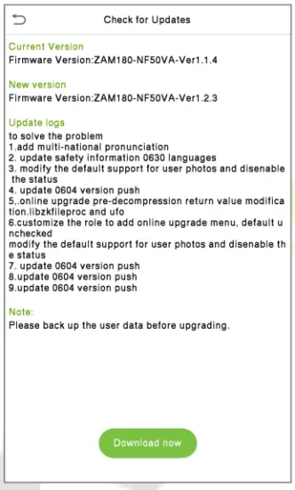
- During the download process, you can press the back button to go to other menus, and then return to this menu to update after the download is complete.

- The download speed is related to the user’s network environment, and it may take about 10 minutes to complete the download. The update may take about 3 minutes.

- After the update is complete, the device will prompt to restart. After restarting, you can enter the System Information to view the latest firmware version after the update.

6.9 Factory Reset
The Factory Reset function restores the device settings such as communication settings and system settings, to the default factory settings (This function does not clear registered user data).
Tap Reset on the System interface and then tap OK to restore the default factory settings.

Personalize Settings
Tap Personalize on the Main Menu interface to customize interface settings, voice, bell, punch state options and shortcut key mappings.

7.1 User Interface Settings
Tap User Interface on the Personalize interface to customize the display style of the main interface.

Function Description
| Function Name | Description |
| Wallpaper | The main screen wallpaper can be selected according to the user preference. |
| Language | Select the language of the device. |
| Menu Timeout (s) | When there is no operation, and the time exceeds the set value, the device will automatically go back to the initial interface. The function either can be disabled or set the required value between 60 and 99999 seconds. |
| Idle Time to Slide Show (s) | When there is no operation, and the time exceeds the set value, a slide show will be played. The function can be disabled, or you may set the value between 3 and 999 seconds. |
| Slide Show Interval (s) | It is the time interval in switching between different slide show photos. The function can be disabled, or you may set the interval between 3 and 999 seconds. |
| Idle Time to Sleep (m) | If the sleep mode is activated, and when there is no operation in the device, then the device will enter standby mode. Tap the screen anywhere to resume normal working mode. This function can be disabled or set a value within 1-999 minutes. |
| Main Screen Style | The main screen style can be selected according to the user preference. |
7.2 Voice Settings
Tap Voice on the Personalize interface to configure the voice settings.

Function Description
| Function Name | Description |
| Voice Prompt | Toggle to enable or disable the voice prompts during function operations. |
| Touch Prompt | Toggle to enable or disable the keypad sounds. |
| Volume | Adjust the volume of the device which can be set between 0 to 100. |
7.3 Bell Schedules
Tap Bell Schedules on the Personalize interface to configure the Bell settings.

- New bell schedule
Tap New Bell Schedule on the Bell Schedule interface to add a new bell schedule.

Function Description
| Function Name | Description |
| Bell Status | Toggle to enable or disable the bell status. |
| Bell Time | Once the required time is set, the device will automatically trigger to ring the bell during that time. |
| Repeat | Set the required number of counts to repeat the scheduled bell. |
| Ring Tone | Select a ring tone. |
| Internal Bell Delay(s) | Set the replay time of the internal bell. Valid values range from 1 to 999 seconds. |
- All bell schedules:
Once the bell is scheduled, on the Bell Schedules interface, tap All Bell Schedules to view the newly scheduled bell. - Edit the scheduled bell:
On the All Bell Schedules interface, tap on the required bell schedule, and tap Edit to edit the selected bell schedule. The editing method is the same as the operations of adding a new bell schedule. - Delete a bell: On the All Bell Schedules interface, tap the required bell schedule, and tap Delete, and then tap Yes to delete the selected bell.
7.4 Punch States Options
Tap Punch States Options on the Personalize interface to configure the punch state settings.

Function Description
| Function Name | Description |
| Punch State Mode | Off: Disable the punch state function. Therefore, the punch state key set under Shortcut Key Mappings menu will become invalid. Manual Mode: Switch the punch state key manually, and the punch state key will disappear after Punch State Timeout. Auto Mode: The punch state key will automatically switch to a specific punch status according to the predefined time schedule which can be set in the Shortcut Key Mappings. Manual and Auto Mode: The main interface will display the auto-switch punch state key. However, the users will still be able to select alternative that is the manual attendance status. After timeout, the manual switching punch state key will become auto-switch punch state key. Manual Fixed Mode: After the punch state key is set manually to a particular punch status, the function will remain unchanged until being manually switched again. Fixed Mode: Only the manually fixed punch state key will be shown. Users cannot change the status by pressing any other keys. |
7.5 Shortcut Key Mappings
Users may define shortcut keys for attendance status and for functional keys which will be defined on the main interface. So, on the main interface, when the shortcut keys are pressed, the corresponding attendance status or the function interface will be displayed directly.
Tap Shortcut Key Mappings on the Personalize interface to set the required shortcut keys.

- On the Shortcut Key Mappings interface, tap on the required shortcut key to configure the shortcut key settings.
- On the Shortcut Key (that is “F1”) interface, tap function to set the functional process of the shortcut key either as punch state key or function key.
- If the Shortcut key is defined as a function key (such as New user, All users, etc.), the configuration is completed as shown in the image below.

- If the Shortcut key is set as a punch state key (such as check in, check out, etc.), then it is required to set the punch state value (valid value 0~250), name.
Note: When the function is set to Undefined, the device will not enable the punch state key. - Set the Switch Time
- The switch time is set in accordance with the punch state options.
- On the Punch States Options interface, when the punch state mode is set to auto mode, the switch time should be set.
- On the Shortcut Key interface, tap Set Switch Time to set the switch time.
- On the Switch Cycle interface, select the switch cycle (Monday, Tuesday etc.) as shown in the image below.
- Once the Switch cycle is selected, set the switch time for each day and tap OK to confirm, as shown in the image below.

Data Management
On the Main Menu, tap Data Mgt. to delete the relevant data in the device.
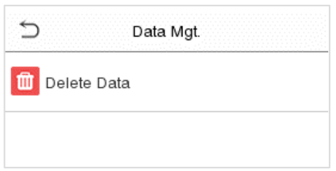
8.1 Delete Data
Tap Delete Data on the Data Mgt. interface to delete the required data. 
Function Description
| Function Name | Description |
| Delete Access Records | To delete access records conditionally. |
| Delete Attendance Photo | To delete attendance photos of designated personnel. |
| Delete Blocklist Photo | To delete the photos taken during failed verifications. |
| Delete All Data | To delete information and attendance logs/access records of all registered users. |
| Delete Admin Role | To remove all administrator privileges. |
| Delete Access Control | To delete all access data. |
| Delete User Photo Templates |
To delete user photo templates in the device. When deleting template photos, there is a risk reminder: “Face re-registration is required after an algorithm upgrade.” |
| Delete Profile Photo | To delete all user photos in the device. |
| Delete Wallpaper | To delete all wallpapers in the device. |
| Delete Screen Savers | To delete the screen savers in the device. |
| Delete Contact List | To delete all contact list of video intercom in the device. |
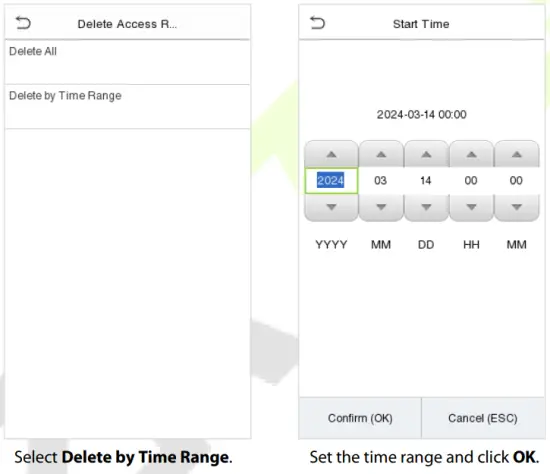
The user may select Delete All or Delete by Time Range when deleting the access records, attendance photos or block listed photos. Selecting Delete by Time Range, you need to set a specific time range to delete all data within a specific period.
Intercom
Click Video intercom Parameters on the System interface.
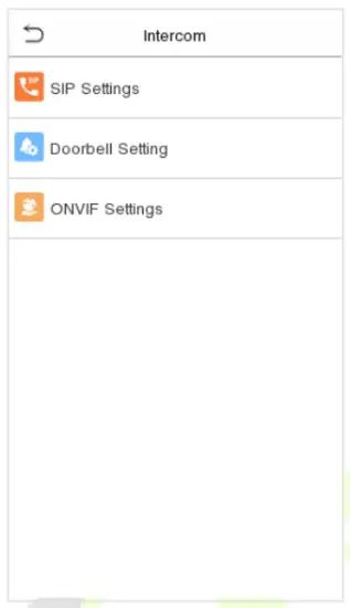
9.1 SIP Settings
Note: This function needs to be used with the indoor station.
Tap SIP Settings on the Video intercom Parameters interface to go to the monitoring SIP settings.

Function Description
| Function Name | Description | |
| Local Settings | SIP Server | Select whether to enable the server address. Once enabled, you need to set the server address, server port, display name, user name and password. |
| Master Account Settings | Select whether to enable the master server address. Once enabled, you need to set the server address, server port, display name, user name and password. Note: Turning off this feature disables the SIP server function. Enable Domain Mode: Select whether to enable domain mode. Server Address: Enter the server address. Server Port: Enter the server port. Display Name: Enter the display name of the server. User Name: Enter the user name of the server. Verify ID: Enter the authentication ID of the server. Password: Enter the password of the server. Transport Protocol: Set the transmission protocol between the device and indoor unit. |
|
| Backup Account Settings | Select whether to enable the backup server address. Once enabled, you need to set the server address, server port, display name, user name and password. Enable Domain Mode: Select whether to enable domain mode. Server Address: Enter the server address. Server Port: Enter the server port. Display Name: Enter the display name of the server. User Name: Enter the user name of the server. Verify ID: Enter the authentication ID of the server. Password: Enter the password of the server. Transport Protocol: Set the transmission protocol between the device and indoor unit. |
|
| Device Port | When using the LAN for visual intercom, enter the network port number of the LAN. | |
| Device Type | You can set the type of the device as entrance station, access control terminal or fence terminal. | |
| Local Information | Set the information of the householder that the device specifically corresponds to, including block, unit, floor and door. | |
| Transport Protocol | Set the transmission protocol between the device and indoor unit. | |
| Call Options | Calling Delay(s) | Set the duration of the calling, valid values are 30 to 60 seconds. |
| Talking Delay(s) | Set the duration of the talking, valid values are 60 to 120 seconds. | |
| Call Volume Settings | Set the volume of the call, valid values are 0 to 100. | |
| Call Type | Set the type of the call to voice only or voice + video. | |
| Call Button Style | Change the visual intercom call button on the standby interface of the device, optional doorbell label |
|
| Auto Answer Settings | When the indoor unit dials the device successfully, it is automatically connected within the set answer time. | |
| Encryption | Whether to enable intercom call encryption function. | |
| Contact List | When the SIP server is disabled, you can add the device number and call address of the indoor unit here. | |
| Calling Shortcut Settings | Set the quick call shortcuts in the call interface of visual intercom, the system defaults 5 shortcuts, including a management center and 4 customizable shortcuts. After enabling the shortcuts, customize the name, enter the device number set in the Contact List, then automatically match the IP address, after the operation is completed, then click on the generated customized name (shortcut) in the call interface of the visual intercom to call directly. Support standard mode and direct calling mode, in direct calling mode, users can call multiple indoor units at the same time. Note: When the SIP server is enabled, Direct Calling Mode can only call the Management Center. |
|
| Advanced Settings | Set the DTMF type and DTMF value of the device, the value should be set to the same as the DTMF value of the indoor unit. | |
9.1.1 Connecting to SIP Server
Note: When the SIP server is enabled, it is advised to select TCP mode first and UDP mode second, because
TCP mode is more stable. When this function is enabled, the Contact List are not displayed.
Tap SIP Settings > Local Settings on the Video intercom Parameters interface to go to the monitoring parameter settings. 
- On SenseFace 4 Series device, tap Local Settings on the SIP Settings interface, after the device is rebooted, enter the server-related parameters.
- Once the SIP is set up correctly, a green dot will appear in the upper right corner of the call page to indicate that the SenseFace 4 Series device is connected to the server. You can call the IP address of the indoor station.
Note: When users need to enable SIP server, they need to purchase the server address and password from the distributor, or build the server confidently.


For details on the operation and use of the indoor station, please refer to the Indoor Station User Manual.
9.1.2 Local Area Network Use
Note: When the SIP Server is disabled and the LAN is used, the UDP mode is selected first.
Set the IP address on the indoor station, Tap Menu > Advanced > Network > 1. Network > 1. IPv4.

- Directly Enter the IP Address of the Indoor Station
Once the indoor station is configured with the network, the video intercom function can be realized by tap the icon on the SenseFace 4 Series device screen and entering the IP address of the indoor station in the jumping interface.
- Contact List
Note: When the SIP server is enabled, the Contact List are not displayed.
- Tap SIP Settings > Contact List on the Video intercom Parameters interface.

- Click Add, input device number and call address to add a new contact member.
Note: Call address and the SenseFace 4 Series device must be in the same network segment.
Function Description
| Function Name | Description |
| Device Number | It is the dialing number in the configuration data, you can enter the value on Sense Face 4 Series device to call the indoor station quickly for video intercom. (For example, 101 corresponds to 00.01.01 in the Device Number setting.) |
| Call Address | The IP address on the indoor station. |
Calling Shortcut Settings
- On SenseFace 4 Series device, tap Calling Shortcut Settings, select any item except admin, and enter the form information you just uploaded.
 Function Description
Function Name Description Name You can customize any character (support Chinese, English, numbers, symbols, etc.) that will be displayed on the call page. Device Number It is the dialing number in the configuration data, you can enter the value on SenseFace 4 Series device to call the indoor station quickly for video intercom. IP Address Enter the device number set in the Contact List, then automatically match the IP address. - Then you can enter the device number or click shortcut key in the call screen to directly implement the video intercom.

Direct Calling Mode
Note: When the SIP server is enabled, Direct Calling Mode can only call the Management Center.
- On the SIP Settings interface, click on Calling Shortcut Settings > Call Mode > Direct Calling Mode > Add. Select the IP addresses of the indoor stations that you want to call, then the indoor stations will be displayed in the list.

- Then you can tap the icon on the device to call the indoor stations at the same time.

9.2 Doorbell Setting
Tap Doorbell Setting on the Video intercom Parameters interface to go to the monitoring doorbell setting.

Function Description
| Function Name | Description |
| Doorbell Only | Tap |
| Video Intercom Only | Tap |
| Doorbell + Video Intercom | Tap |
9.2.1 Connect the Wireless Doorbell★
Note: This function needs to be used with the wireless doorbell.
- First, power on the wireless doorbell. Then, press and hold the music button
 for 1.5 seconds until the indicator flashes to indicate it’s in pairing mode. After that, click on the SenseFace 4 Series device icon , if the wireless doorbell rings and the indicator flashes, it means the connection is successful.
- After a successful pairing, clicking the iconof SenseFace 4 Series device will ring the wireless doorbell.
Note: Generally, each SenseFace 4 Series device connects to 1 wireless doorbell.
Unbinding the Wireless Doorbell
Power off the wireless doorbell first, then re-installing the batteries while pressing and holding the music button ![]() until the indicator is on, indicating that the unbinding is successful.
until the indicator is on, indicating that the unbinding is successful.
9.3 ONVIF Settings
Note: This function needs to be used with the network video recorder (NVR).
- Set the device to the same network segment as the NVR.
- Tap ONVIF Settings on the Video intercom Parameters interface.
 Function Description
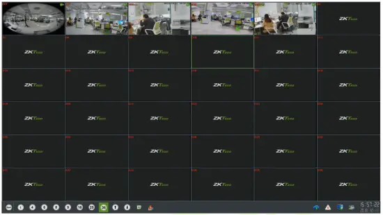
Function Name Description Enable Authentication Enable/Disable the Authentication Function. When it is disabled, there is no need to input the User Name and Password when adding the device to the NVR. User Name Set the User Name. The default is admin. Password Set the password. The default is admin. Server Port The default is 8000, and cannot be modified. - On the NVR system, click on [Start] > [Menu], then the main menu will pop up.

- Click [Channel Manage] > [Add Channel] > [Refresh] to search for the device.

- Select the checkbox for the device you want to add and edit the parameters in the corresponding text field, then click on [OK] to add it to the connection list.
 Note: The User Name and Password is set in the ONVIF Settings of the device.
 - After adding successfully, the video image obtaining from the device can be viewed in real-time.
For more details, please refer to the NVR User Manual.
Access Control
On the Main Menu, tap Access Control to set the schedule of door opening, locks control and to configure other parameters settings related to access control.

To gain access, the registered user must meet the following conditions:
- The relevant door’s current unlock time should be within any valid time zone of the user time period.
- The corresponding user’s group must be already set in the door unlock combination (and if there are other groups, being set in the same access combo, then the verification of those group’s members are also required to unlock the door).
- In default settings, new users are allocated into the first group with the default group time zone, where the access combo is “1” and is set in unlock state by default.
10.1 Access Control Options
Tap Access Control Options on the Access Control interface to set the parameters of the control lock of the terminal and related equipment.

Function Description
| Function Name | Description |
| Gate Control Mode | Toggle between ON or OFF switch to get into gate control mode or not. When set to ON, on this interface will remove Door lock relay, Door sensor relay and Door sensor type options. |
| Door Lock Delay (s) | The length of time that the device controls the electric lock to be in unlock state. Valid value: 1~10 seconds; 0 second represents disabling the function. |
| Door Sensor Delay (s) | If the door is not locked and is being left open for a certain duration (Door Sensor Delay), an alarm will be triggered. The valid value of Door Sensor Delay ranges from 1 to 255 seconds. |
| Door Sensor Type | There are three Sensor types: None, Normal Open and Normal Closed. None: It means door sensor is not in use. Normal Open: It means the door is always left opened when electric power is on. Normal Closed: It means the door is always left closed when electric power is on. |
| Verification Mode | The supported verification mode includes Card/Fingerprint, Fingerprint Only, Card Only, Fingerprint + Password, Card + Password, Card + Fingerprint and Card + Fingerprint + Password. |
| Door Available Time Period | To set time period for door, so that the door is available only during that period. |
| Normal Open Time Period | Scheduled time period for “Normal Open” mode, so that the door is always left open during this period. |
| Master Device | When setting up the master, the status of the master can be set to exit on enter. Out: The record verified on the host is the exit record. In: The record verified on the host is the entry record. |
| Slave Device | When setting up the slave, the status of the slave can be set to exit on enter. Out: The record verified on the host is the exit record. In: The record verified on the host is the entry record. |
| Auxiliary Input Configuration | Sets the door unlock time period and auxiliary output type of the auxiliary terminal device. Auxiliary output types include None, Trigger door open, Trigger Alarm, Trigger door open and Alarm. |
| Verify Mode by RS485 | The verification mode is used when the device is used either as a host or slave. The supported verification mode includes Card Only and Card + Password. |
| Speaker Alarm | Transmits a sound alarm or disassembly alarm from the local. When the door is closed or the verification is successful, the system will cancel the alarm from the local. |
| Reset Access Settings | The access control reset parameters include door lock delay, door sensor delay, door sensor type, verification mode, door available time period, normal open time period, master device, and alarm. However, erased access control data in Data Mgt. is excluded. |
10.2 Time Rule Setting
Tap Time Rule Setting on the Access Control interface to configure the time settings.
- The entire system can define up to 50 Time Periods.
- Each Time Period represents 10 Time Zones, i.e. 1 week and 3 holidays, and each time zone is a standard 24 hour period per day and the user can only verify within the valid time period.
- One can set a maximum of 3 time periods for every time zone. The relationship among these time periods is “OR”. Thus, when the verification time falls in any one of these time periods, the verification is valid.
- The Time Zone format of each Time Period: HH MM-HH MM, which is accurate to minutes according to the 24-hour clock.
Tap the grey box to search the required Time Zone and specify the required Time Zone number (maximum: up to 50 zones).
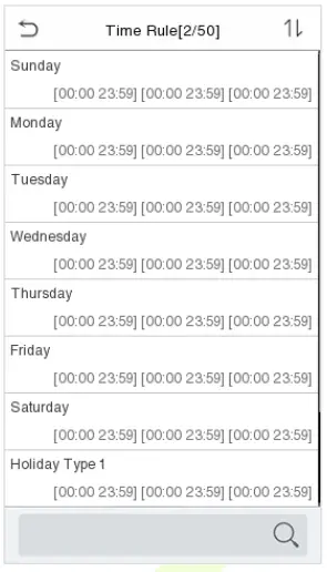
On the selected Time Zone number interface, tap on the required day (that is Monday, Tuesday etc.) to set the time.
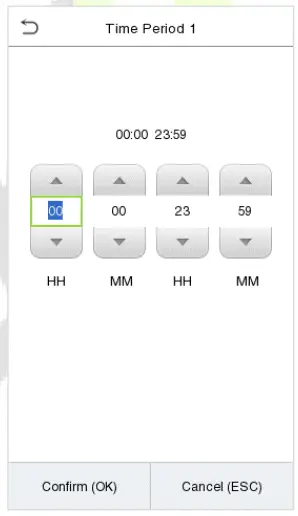
Specify the start and the end time, and then tap OK.
Notes:
- When the End Time is earlier than the Start Time, (such as 23:57~23:56), it indicates that access is prohibited all day.
- When the End Time is later than the Start Time, (such as 00:00~23:59), it indicates that the interval is valid.
- The effective Time Period to keep the Door Unlock or open all day is (00:00~23:59) or also when the Ending Time is later than the Starting Time, (such as 08:00~23:59).
- The default Time Zone 1 indicates that door is open all day long.
10.3 Holidays
Whenever there is a holiday, you may need a special access time; but changing everyone’s access time one by one is extremely cumbersome, so you can set a holiday access time which is applicable to all employees, and the user will be able to open the door during the holidays.
Tap Holidays on the Access Control interface to set the Holiday access.
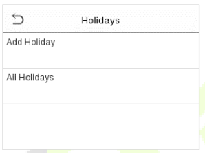
Add a new holiday:
Tap Add Holiday on the Holidays interface and set the holiday parameters.

- Edit a holiday:
On the Holidays interface, select a holiday item to be modified. Tap Edit to modify holiday parameters. - Delete a Holiday:
On the Holidays interface, select a holiday item to be deleted and tap Delete. Press OK to confirm deletion. After deletion, this holiday is no longer displayed on All Holidays interface.
10.4 Access Groups★
Note: This function is only available for T&A PUSH.
This is to easily manage groupings and users in different access groups. Settings of an access group such as access time zones are applicable to all members in the group by default. However, users may manually set the time zones as needed. User authentication takes precedence over group authentication when group authentication modes overlap with the individual authentication methods. Each group can set a maximum of three time zones. By default, newly enrolled users are assigned to Access Group 1; they can be assigned to other access groups.
Click Access Groups on the Access Control interface.

Add a New Group
Click New Group on the Access Groups interface and set access group parameters.

Notes:
- There is a default access group numbered 1, which cannot be deleted, but can be modified.
- A number cannot be modified after being set.
- When the holiday is set to be valid, personnel in a group may only open the door when the group time zone overlaps with the holiday time period.
- When the holiday is set to be invalid, the access control time of the personnel in a group is not affected during holidays.
10.5 Combined Verification
Access groups are arranged into different door-unlocking combinations to achieve multiple verifications and strengthen the security. In a door-unlocking combination, the range of the combined number N is: 0 ≤ N ≤ 5, and the number of members N may all belong to one access group or may belong to five different access groups.
Tap Combined Verification on the Access Control interface to configure the combined verification setting.

On the combined verification interface, tap the Door-unlock combination to be set, and tap the up and down arrows to input the combination number, and then press OK.
For Example:
- The Door-unlock combination 1 is set as (01 03 05 06 08), indicating that the unlock combination 1 consists of 5 people, and the 5 individuals are from 5 groups, namely, Access Control Group 1 (AC group 1), AC group 3, AC group 5, AC group 6, and AC group 8, respectively.
- The Door-unlock combination 2 is set as (02 02 04 04 07), indicating that the unlock combination 2 consists of 5 people; the first two are from AC group 2, the next two are from AC group 4, and the last person is from AC group 7.
- The Door-unlock combination 3 is set as (09 09 09 09 09), indicating that there are 5 people in this combination; all of which are from AC group 9.
- The Door-unlock combination 4 is set as (03 05 08 00 00), indicating that the unlock combination 4 consists of only three people. The first person is from AC group 3, the second person is from AC group 5, and the third person is from AC group 8.
Delete a Door-unlocking Combination:
Set all Door-unlock combinations to 0 if you want to delete door-unlock combinations.
10.6 Anti-passback Setup
It is possible that users may be followed by some persons to enter the door without verification, resulting in a security breach. So, to avoid such a situation, the Anti-Passback option was developed. Once it is enabled, the check-in record must match with the check-out record so as to open the door. This function requires two devices to work together: one is installed inside the door (master device), and the other one is installed outside the door (slave device). The two devices communicate via the Wiegand signal. The Wiegand format and Output type (User ID / Card Number) adopted by the master device and slave device must be consistent.
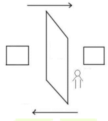
Tap Anti-passback Setup on the Access Control interface.

Function Description
| Function Name | Description |
| Anti-passback Direction | No Anti-passback: Anti-passback function is disabled, which means successful verification through either the master device or slave device can unlock the door. The attendance state is not saved in this option. Out Anti-passback: After a user checks out, only if the last record is a check-in record, the user can check-out again; otherwise, the alarm will be triggered. However, the user can check-in freely. In Anti-passback: After a user checks in, only if the last record is a check-out record, the user can check-in again; otherwise, the alarm will be triggered. However, the user can check-out freely. In/Out Anti-passback: After a user checks in/out, only if the last record is a check-out record, the user can check-in again; or if it is a check-in record, the user can check-out again; otherwise, the alarm will be triggered. |
10.7 Duress Options
Once a user activates the duress verification function with specific authentication method(s), and when he/she is under coercion and authenticates using duress verification, the device will unlock the door as usual, but at the same time, a signal will be sent to trigger the alarm. On Access Control interface, tap Duress Options to configure the duress settings.

Function Description
| Function Name | Description |
| Alarm on Password | When a user uses the password verification method, an alarm signal will be generated, otherwise there will be no alarm signal. |
| Alarm on 1:1 Match | When a user uses any fingerprint to perform the 1:1 verification, an alarm signal will be generated, otherwise there will be no alarm signal. |
| Alarm on 1:N Match | When a user uses any fingerprint to perform 1:N verification, an alarm signal will be generated, otherwise there will be no alarm signal. |
| Alarm Delay(s) | Alarm signal will not be transmitted until the alarm delay time is elapsed. The value ranges from 1 to 999 seconds. |
| Duress Password | Set the 6-digit duress password. When the user enters this duress password for verification, an alarm signal will be generated. |
USB Manager
You can import the user information, and attendance data in the machine to matching attendance software for processing by using a USB disk, or import the user information to other devices for backup.
Before uploading/downloading data from/to the USB disk, insert the USB disk into the USB slot first.
Note: Only FAT32 format is supported when downloading data using USB disk.
Tap USB Manager on the main menu interface.

11.1 USB Download
On the USB Manager interface, tap Download.

Function Description
| Function Name | Description |
| Attendance Data | To download all attendance data in specified time period into USB disk. |
| User Data | To download all user information from the device into USB disk. |
| User Portrait | To download all user portraits from the device into USB disk. |
| Attendance Photo | To download all attendance photos from the device into USB disk. |
| Blocklist Photo | To download all blocklisted photos (photos taken after failed verifications) from the device into USB disk. |
11.2 USB Upload
On the USB Manager interface, tap Download. 
Function Description
| Function Name | Description |
| Screen Saver | To upload all screen savers from USB disk into the device. You can choose Upload selected photo or upload all photos. The images will be displayed on the device’s main interface after upload. |
| Wallpaper | To upload all wallpapers from USB disk into the device. You can choose Upload selected photo or upload all photos. The images will be displayed on the screen after upload. |
| User Data | To upload all the user information from USB disk into the device. |
| User Portrait | To upload all user portraits from USB disk into the device. |
Attendance Search
Once the identity of a user is verified, the Event Logs will be saved in the device. This function enables users to check their access records.
Click Attendance Search on the Main Menu interface to search for the required Access/Attendance log.

The process of searching for attendance and blocklist photos is similar to that of searching for event logs. The following is an example of searching for event logs.
On the Attendance Search interface, tap Event Logs to search for the required record.
- Enter the user ID to be searched and click OK. If you want to search for logs of all users, click OK without entering any user ID.
- Select the time range in which the logs need to be searched.

- Once the log search succeeds. Tap the login highlighted in green to view its details.
- The below figure shows the details of the selected log.

Autotest
On the Main Menu, tap Autotest to automatically test whether all modules in the device function properly, which include the LCD, Voice, Camera and Real-Time Clock (RTC).

Function Description
| Function Name | Description |
| Test All | To automatically test whether the LCD, Audio, Camera and RTC are normal. |
| Test LCD | To automatically test the display effect of LCD screen by displaying full- color, pure white, and pure black to check whether the screen displays colors normally. |
| Test Voice | To automatically test whether the audio files stored in the device are complete and the voice quality is good. |
| Microphone Test | Check whether the microphone is working by speaking to microphone and playing the microphone recording. |
| Test Fingerprint Sensor | To test the fingerprint sensor by pressing a finger on the scanner to check if the acquired fingerprint image is clear. When you are pressing a finger on the scanner, the fingerprint image will display on the screen. |
| Cam Test | To test if the camera functions properly by checking the photos taken to see if they are clear enough. (Same as “Test Face”.) |
| Test Clock RTC | To test the RTC. The device tests whether the clock works normally and accurately with a stopwatch. Tap the screen to start counting and press it again to stop counting. |
System Information
On the Main Menu, tap System Info to view the storage status, the version information of the device, and firmware information.

Function Description
| Function Name | Description |
| Device Capacity | Displays the current device’s user storage, password, face template, fingerprint and card storage, access records, attendance and blocklist photos, and profile photos. |
| Device Info | Displays the device’s name, serial number, MAC address, fingerprint algorithm★, face template algorithm, platform information, MCU Version and manufacture date. |
| Firmware Info | Displays the firmware version and other version information of the device. |
| Privacy Policy | The privacy policy control will appear when the gadget turns on for the first time. After clicking “I have read it,” the customer can use the product regularly. Click System Info > Privacy Policy to view the content of the privacy policy. The privacy policy’s content does not allow for U disc export. Note: The current privacy policy’s text is only available in Simplified Chinese/ English. However, translation of other multi-language content is underway, with more iterations. |
Connecting to ZKBio Zlink Web
Change the device communication protocol to BEST protocol, then the device can be managed by ZKBio Zlink, please refer to Device Type Setting.
Users can use the created account to access ZKBio Zlink Web to connect devices, add new personnel, register the verification method of registered personnel, synchronize personnel to devices and query records.
15.1 Register Account
- Access the ZKBio Zlink website (http://zlink.minervaiot.com).
- If you do not have an account, please click create account to add a new account.

- Read and agree to User Agreement and Privacy Policy, then click Register.

- Enter user’s information and set password, then click Register.

- Set the organization’s name and Organization code, click Create, then complete registration. If you do have an organization, please click Select an Organization.

15.2 Add Device
15.2.1 Set Organization (Add Person)
- Click Me > Organization on the main menu.

- Click Add icon
 to add a new person (Repeat adding the department, role and permission, job title, site list, and zone list).
- Enter the person’s details and click Save (Repeat adding the department, role and permission, job title, site list, and zone list).
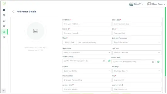
15.2.2 Add Device
- Tap COMM. > Ethernet in the main menu on the device to set the IP address and gateway of the device.
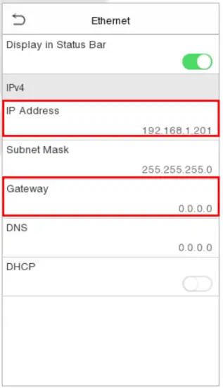
- Click Workshop > CloudACC on the main menu to enter the ZKBio Cloud Access interface.
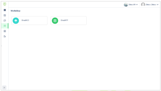
- Click Device Management > Device to enter the Device interface in the ZKBio Cloud Access
- Click +Add Device button to add a new device.
- Read and check to the instructions, then click Continue.
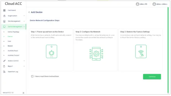
- Enter the device’s serial number, then click Add. (Click System Info > Device Info on the device to view the serial number)
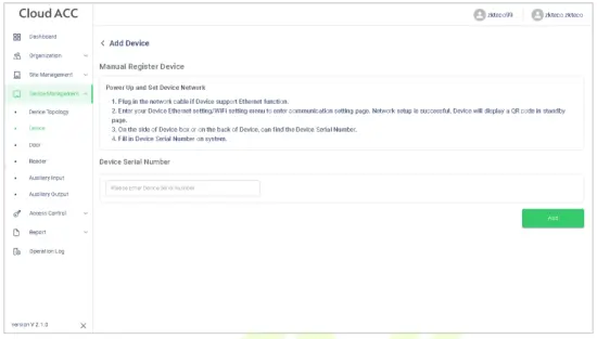
- Choose a site and a zone, then click Save to finish.
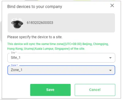
15.3 Time Slot
Time Slot is used to set the access time period for person or doors.
15.3.1 Set Time Slot
In ZKBio Cloud Access interface, click Access Control > Time Slots to set time slot.

Click +Add Time slots to add a new slot, or click![]() to modify an existing slot.
to modify an existing slot.
15.3.2 Set Door Access Time
In ZKBio Cloud Access interface, click Access Control > Door Access Time and click![]() to allocate a time slot to this door.
to allocate a time slot to this door.

15.3.3 Set Group Access Time
You can set a group to control the access time of the person and the door at the same time.
In ZKBio Cloud Access interface, click Access Control > Group Access Time.

Click + Add Group Access Time to add a new group.
Click ![]() to allocate doors to this group.
to allocate doors to this group.
Click ![]() to allocate person to this group.
to allocate person to this group.
Click ![]() to allocate a time slot to this group.
to allocate a time slot to this group.
Click![]() to delete this group.
to delete this group.
15.4 Synchronize Person to Device
- Click Workshop > CloudACC on the main menu to enter the ZKBio Cloud Access interface.

- Click Access Control > Group Access Time.

- Click
 > to choose a device.
- Click
 > to allocate person to this device.
- Click Device Management > Device to enter the Device interface.

- Choose a device and click Persons in the Device icon
 to view the person list.
15.5 User Registration
15.5.1 Register a User ID and Name
Please refer to 15.2.1 Set Organization.
15.5.2 Setting the User Role
There are two types of user accounts: the Normal User and the Super Admin. If there is already a registered administrator, the normal users have no rights to manage the system and may only access authentication verifications. The administrator owns all management privileges.
- Click Device Management > Device on ZKBio Cloud Access interface to enter the Device interface.
- Choose a device and click Persons in the Device icon to view the person list.

- Choose the Select User role.

15.5.3 Register Fingerprint
- Click Device Management > Device on ZKBio Cloud Access interface to enter the Device interface.
- Choose a device and click Persons in the Device icon to view the person list.

- Click icon
 to choose a finger, click Submit, then register fingerprint on the device.
- Press the same finger on the fingerprint reader three times. Green indicates that the fingerprint was enrolled successfully.

15.5.4 Register Face Template
- Click Device Management > Device on ZKBio Cloud Access interface to enter the Device interface.
- Choose a device and click Persons in the Device icon to view the person list.

- Click
 icon to register face template on the device.
The registration interface is as follows:

15.5.5 Register Password
- Click Device Management > Device on ZKBio Cloud Access interface to enter the Device interface.
- Choose a device and click Persons in the Device icon to view the person list.

- Click
 icon to register password on the device.

The registration interface is as follows:

Note: The password may contain one to eight digits by default.
15.5.6 Register Card
- Click Device Management > Device on ZKBio Cloud Access interface to enter the Device interface.
- Choose a device and click Persons in the Device icon to view the person list.

- Click
 icon to register password on the device.

The registration interface is as follows:

15.6 Data Search
15.6.1 Dashboard
In ZKBio Cloud Access interface, click Dashboard to check the sites, devices, doors, person of this application, events overview graph, and sites overview map.

15.6.2 Event Report
In ZKBio Cloud Access interface, click Report > Events to check the specific information of all devices’ events.

Connecting to ZKBio Zlink App
Change the device communication protocol to BEST protocol, then the device can be managed by ZKBio Zlink, please refer to Device Type Setting.
Users can use the created account to access ZKBio Zlink App to connect devices, unlock the device remotely and query records.
16.1 Register Account
- Search for the ZKBio Zlink App in Apple App Store or Google Play Store and download the App to your smartphone.
- Open the ZKBio Zlink App and if you do not have an account, please click create account to add a new account.
- Read and agree to User Agreement and Privacy Policy, then click Register.
- Enter user’s information and set password, then click Register.

- Choose an organization, click Enter, then complete registration. If you do not have an organization, please click Create one.

16.2 Add Person
- Click Me > Organization > Person on the main menu.
- Click icon to add a new person. Enter the information, and click Save.


16.3 Add Device
16.3.1 Add Site and Zone
- Click Me > Organization > Site (or Zone) on the main menu.
- Click icon to add a new site or zone. Enter the information, and click Save.


16.3.2 Add Device
- Tap COMM. > Ethernet in the main menu on the device to set the IP address and gateway of the device.

- Click Workshop > CloudACC on the main menu to enter the ZKBio Cloud Access interface.
- Click Me > Device List to enter the Device interface. And click icon to add a new device.
- Click Manually register device.
- Read and check to the instructions, then click Continue.
- Enter the device’s serial number, then click Confirm. (Click System Info > Device Info on the device to view the serial number.)

- Choose a site and a zone, then click Save to finish.
- Then click Device, users can view the device status and unlock remotely in this interface.

Connect to ZKBio CVAccess Software
17.1 Set the Communication Address
Device Side
- Tap COMM. > Ethernet in the main menu to set the IP address and gateway of the device.
Note: Please ensure that the IP address is in the same network segment as the server address and can communicate with the ZKBio CVAccess server. - In the main menu, click COMM. > Cloud Server Setting to set the server address and server port.
Server address: Set the IP address as of ZKBio CVAccess server.
Server port: Set the server port as of ZKBio CVAccess.

Software Side
Login to ZKBio CVAccess software, click System > Communication > Communication Monitor to set the ADMS service port, as shown in the figure below:

17.2 Add Device on the Software
Add the device by searching. The process is as follows:
- Click Access > Device > Search Device, to open the Search interface in the software.
- Click Search, and it will prompt Searching…….
- After searching, the list and total number of access controllers will be displayed.

- Click Add in operation column, a new window will pop-up. Select Icon type, Area, and Add to Level from each dropdown and click OK to add the device.
17.3 Add Personnel on the Software
- Click Personnel > Person > New:

- Fill in all the required fields and click OK to register a new user.
- Click Access > Device > Control > Synchronize All Data to Devices to synchronize all the data to the device including the new users.
17.4 Mobile Credential★
Note: This function is only for SenseFace 4C.
After downloading and installing the ZKBioAccess Mobile Page, the user needs to set the Server before login. The steps are given below:
- In ZKBio CVAccess > System > System Management > Parameters, set Enable QR Code to ‘’Yes’’, and select the QR code status according to the actual situation. The default is Dynamic, the valid time of the QR code can be set.

- On the Server, choose System > Authority Management > Client Register to add a registered App client.

- Open the App on the Smartphone. On the login screen, tap Server Setting and type the IP Address or the domain name of the Server, and its port number.
Note: Smartphone and the Server must be in the same network segment. - Tap the QR Code icon to scan the QR code of the new App client. After the client is identified successfully, set the client’s name and tap Connection Test.
- After the network is connected successfully, tap Save.
 The Mobile Credential function is only valid when logging in as an employee, tap on Employee to switch to employee login screen. Enter the employee ID and password (Default: 123456) to login.
 - Tap Mobile Credential on the App, and a QR code will appear, which includes employee ID and card number (static QR code only includes card number) information.
- The QR code can replace a physical card on a specific device to achieve contactless authentication to open the door.

- When using this function for the first time, the App will prompt to authorize the modification of screen brightness settings, as shown in the figure:
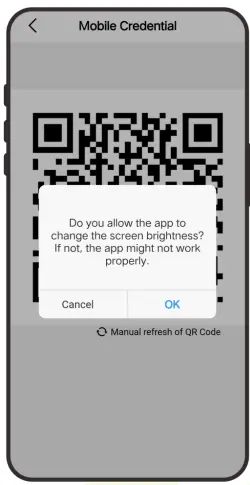
- The QR code refreshes automatically for every 30s and supports manual refresh.
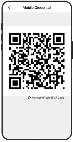
Note: For other specific operations, please refer to ZKBio CVAccess User Manual.
Connect to ZKBioTime Software
18.1 Set the Communication Address
- Tap COMM. > Ethernet in the main menu to set the IP address and gateway of the device.
Note: Please ensure that the IP address is in the same network segment as the server address and can communicate with the ZKBioTime server. - In the main menu, click COMM. > Cloud Server Setting to set the server address and server port.
Server address: Set the IP address as of ZKBioTime server.
Server port: Set the server port as of ZKBioTime (The default is 8081).

18.2 Add Device on the Software
Add the device by searching. The process is as follows:
- Click Device > Device > Add, to add the device on the software.
- A new window pops-up on clicking Add. Enter the required information about the device and click Confirm, then the added devices are displayed automatically.

18.3 Add Personnel on the Software
- Click Personnel > Employee > Add:

- Fill in all the required fields and click Confirm to register a new user.
- Click Device > Device > Data Transfer > Sync Data to Device to synchronize all the data to the device including the new users.
Appendix 1
Requirements of Live Collection and Registration of Visible Light
Face Templates
- It is recommended to perform registration in an indoor environment with an appropriate light source without underexposure or overexposure.
- Do not place the device towards outdoor light sources like door or window or other harsh light sources.
- Dark-color apparels, different from the background color is recommended for registration.
- Please expose your face template and forehead properly and do not cover your face template and eyebrows with your hair.
- It is recommended to show a plain facial expression. (A smile is acceptable, but do not close your eyes, or incline your head to any orientation).
- Two templates are required for a person with eyeglasses, one template with eyeglasses and the other without the eyeglasses.
- Do not wear accessories like a scarf or mask that may cover your mouth or chin.
- Please face template right towards the capturing device, and locate your face template in the template capturing area as shown in the template below.
- Do not include more than one face template in the capturing area.
- A distance of 50cm to 80cm is recommended for capturing the template. (The distance is adjustable, subject to body height).

Requirements for Visible Light Digital Face Template Data
The digital photo should be straight-edged, colored, half-portrayed with only one person, and the person should be uncharted and in casuals. Persons who wear eyeglasses should remain to put on eyeglasses for getting photo captured.
- Eye distance
200 pixels or above are recommended with no less than 115 pixels of distance. - Facial expression
Neutral face template or smile with eyes naturally open are recommended. - Gesture and angel
Horizontal rotating angle should not exceed ±10°, elevation should not exceed ±10°, and depression angle should not exceed ±10°. - Accessories
Masks or colored eyeglasses are not allowed. The frame of the eyeglasses should not cover eyes and should not reflect light. For persons with thick eyeglasses frame, it is recommended to capture two templates, one with eyeglasses and the other one without the eyeglasses. - Face template
Complete face template with clear contour, real scale, evenly distributed light, and no shadow. - Template format
Should be in BMP, JPG or JPEG. - Data requirement
Should comply with the following requirements:
- White background with dark-colored apparel.
- 24bit true color mode.
- JPG format compressed template with not more than 20kb size.
- Resolution should be between 358 x 441 to 1080 x 1920.
- The vertical scale of head and body should be in a ratio of 2:1.
- The photo should include the captured person’s shoulders at the same horizontal level.
- The captured person’s eyes should be open and with clearly seen iris.
- Neutral face template or smile is preferred, showing teeth is not preferred.
- The captured person should be clearly visible, natural in color, no harsh shadow or light spot or reflection in face template or background. The contrast and lightness level should be appropriate.
Appendix 2
Privacy Policy
Notice:
To help you better use the products and services of ZKTeco (hereinafter referred as “we”, “our”, or “us”) a smart service provider, we consistently collect your personal information. Since we understand the importance of your personal information, we took your privacy sincerely and we have formulated this privacy policy to protect your personal information. We have listed the privacy policies below to precisely understand the data and privacy protection measures related to our smart products and services.
Before using our products and services, please read carefully and understand all the rules and provisions of this Privacy Policy. If you do not agree to the relevant agreement or any of its terms, you must stop using our products and services.
I. Collected Information
To ensure the normal product operation and help the service improvement, we will collect the information voluntarily provided by you or provided as authorized by you during registration and use or generated as a result of your use of services.
- User Registration Information: At your first registration, the feature template (Fingerprint template/Face template template/Palm template) will be saved on the device according to the device type you have selected to verify the unique similarity between you and the User ID you have registered. You can optionally enter your Name and Code. The above information is necessary for you to use our products. If you do not provide such information, you cannot use some features of the product regularly.
- Product information: According to the product model and your granted permission when you install and use our services, the related information of the product on which our services are used will be collected when the product is connected to the software, including the Product Model, Firmware Version Number, Product Serial Number, and Product Capacity Information. When you connect your product to the software, please carefully read the privacy policy for the specific software.
II. Product Security and Management
- When you use our products for the first time, you shall set the Administrator privilege before performing specific operations. Otherwise, you will be frequently reminded to set the Administrator privilege when you enter the main menu interface. If you still do not set the Administrator privilege after receiving the system prompt, you should be aware of the possible security risk (for example, the data may be manually modified).
- All the functions of displaying the biometric information are disabled in our products by default. You can choose Menu > System Settings to set whether to display the biometric information. If you enable these functions, we assume that you are aware of the personal privacy security risks specified in the privacy policy.
- Only your user ID is displayed by default. You can set whether to display other user verification information (such as Name, Department, Photo, etc.) under the Administrator privilege. If you choose to display such information, we assume that you are aware of the potential security risks (for example, your photo will be displayed on the device interface).
- The camera function is disabled in our products by default. If you want to enable this function to take pictures of yourself for attendance recording or take pictures of strangers for access control, the product will enable the prompt tone of the camera. Once you enable this function, we assume that you are aware of the potential security risks.
- All the data collected by our products is encrypted using the AES 256 algorithm. All the data uploaded by the Administrator to our products are automatically encrypted using the AES 256 algorithm and stored securely. If the Administrator downloads data from our products, we assume that you need to process the data and you have known the potential security risk. In such a case, you shall take the responsibility for storing the data. You shall know that some data cannot be downloaded for sake of data security.
- All the personal information in our products can be queried, modified, or deleted. If you no longer use our products, please clear your personal data.
III. How we handle personal information of minors
Our products, website and services are mainly designed for adults. Without consent of parents or guardians, minors shall not create their own account. If you are a minor, it is recommended that you ask your parents or guardian to read this Policy carefully, and only use our services or information provided by us with consent of your parents or guardian.
We will only use or disclose personal information of minors collected with their parents’ or guardians’ consent if and to the extent that such use or disclosure is permitted by law or we have obtained their parents’ or guardians’ explicit consent, and such use or disclosure is for the purpose of protecting minors.
Upon noticing that we have collected personal information of minors without the prior consent from verifiable parents, we will delete such information as soon as possible.
IV. Others
You can visit https://www.zkteco.com/cn/index/Index/privacy_protection.html to learn more about how we collect, use, and securely store your personal information. To keep pace with the rapid development of technology, adjustment of business operations, and to cope with customer needs, we will constantly deliberate and optimize our privacy protection measures and policies. Welcome to visit our official website at any time to learn our latest privacy policy.
Eco-friendly Operation
![]() The product’s “eco-friendly operational period” refers to the time during which this product will not discharge any toxic or hazardous substances when used in accordance with the prerequisites in this manual.
The product’s “eco-friendly operational period” refers to the time during which this product will not discharge any toxic or hazardous substances when used in accordance with the prerequisites in this manual.
The eco-friendly operational period specified for this product does not include batteries or other components that are easily worn down and must be periodically replaced. The battery’s eco-friendly operational period is 5 years.
| Hazardous or Toxic substances and their quantities | ||||||
| Component Name | Hazardous/Toxic Substance/Element | |||||
| Lead (Pb) | Mercury (Hg) | Cadmiu m (Cd) | Hexavalent chromium (Cr6+) | Polybrominate d Biphenyls (PBB) | Polybrominated Diphenyl Ethers (PBDE) | |
| Chip Resistor | × | ○ | ○ | ○ | ○ | ○ |
| Chip Capacitor | × | ○ | ○ | ○ | ○ | ○ |
| Chip Inductor | × | ○ | ○ | ○ | ○ | ○ |
| Diode | × | ○ | ○ | ○ | ○ | ○ |
| ESD component | × | ○ | ○ | ○ | ○ | ○ |
| Buzzer | × | ○ | ○ | ○ | ○ | ○ |
| Adapter | × | ○ | ○ | ○ | ○ | ○ |
| Screws | ○ | ○ | ○ | × | ○ | ○ |
| ○ indicates that the total amount of toxic content in all the homogeneous materials is below the limit as specified in SJ/T 11363—2006. × indicates that the total amount of toxic content in all the homogeneous materials exceeds the limit as specified in SJ/T 11363—2006. Note: 80% of this product’s components are manufactured using non-toxic and eco-friendly materials. The components which contain toxins or harmful elements are included due to the current economic or technical limitations which prevent their replacement with non-toxic materials or elements. |
||||||

ZKTeco Industrial Park, No. 32, Industrial Road,
Tangxia Town, Dongguan, China.
Phone : +86 769 – 82109991
Fax : +86 755 – 89602394
www.zkteco.com
Copyright © 2024 ZKTECO CO., LTD. All Rights Reserved.
Documents / Resources
 |
ZKTECO SenseFace 4 Series Access Control Terminal [pdf] User Manual 21011, 2AJ9T-21011, 2AJ9T21011, SenseFace 4 Series Access Control Terminal, SenseFace 4 Series, Access Control Terminal, Control Terminal, Terminal |