Xinsilu 2AZKV-IP IP Smart Wi-Fi Video Intercom System

Please read this manual carefully before use to ensure the correct use of this product.
Product Structure
Indoor Unit
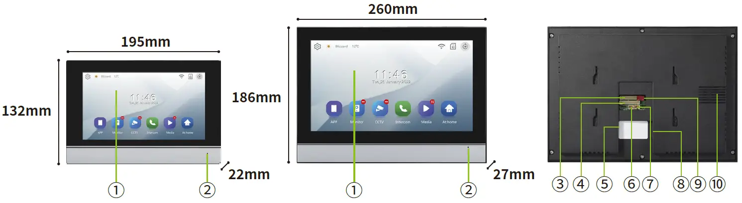
- IPS Touch Screen
- Microphone
- RJ45 Network Interface Port
- Eight-zone Anti-intrusion Port
- TF Card Slot
- 2P Doorbell Port (NO, COM Detection Switch)
- 2P Doorbell Port (Relay Switch)
- RJ45 Network Port
- DC15 1.2A Power Port
- Speaker
Outdoor Unit
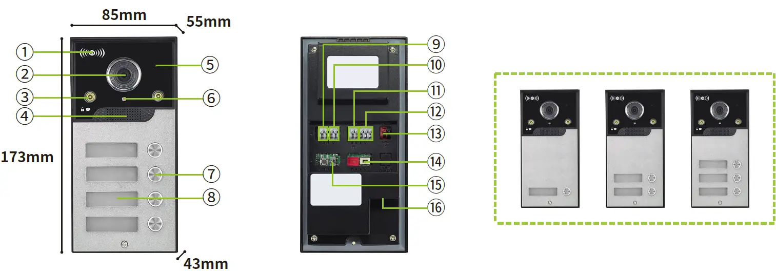
- ID Card Swipe Area
- High-definition Camera
- Infrared Night Vision Light
- Speaker
- Microphone
- Photoresistor
- Call Button
- Nameplate Area
- Exit Button Signal (PUSH, GND)
- Door Magnetic Switch Signal(COM, NC)
- Electric Lock Signal (L+, L-)
- NC, COM, NO (Switched Signal)
- DC15 1.2A Power Port
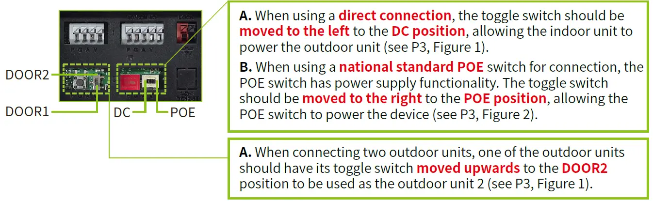
- DC Power/POE Power Toggle Switch
- DOOR1/DOOR2 Toggle Switch
- RJ45 Network Port
Product Parameters
Indoor Unit


Outdoor Unit

Product Wiring
Notes
- Wiring diagrams use national standard POE switches with the capability to power the indoor unit.
- If a POE switch without power supply functionality is used, a DC15V1.2A power supply must be used to power the indoor and outdoor units separately.
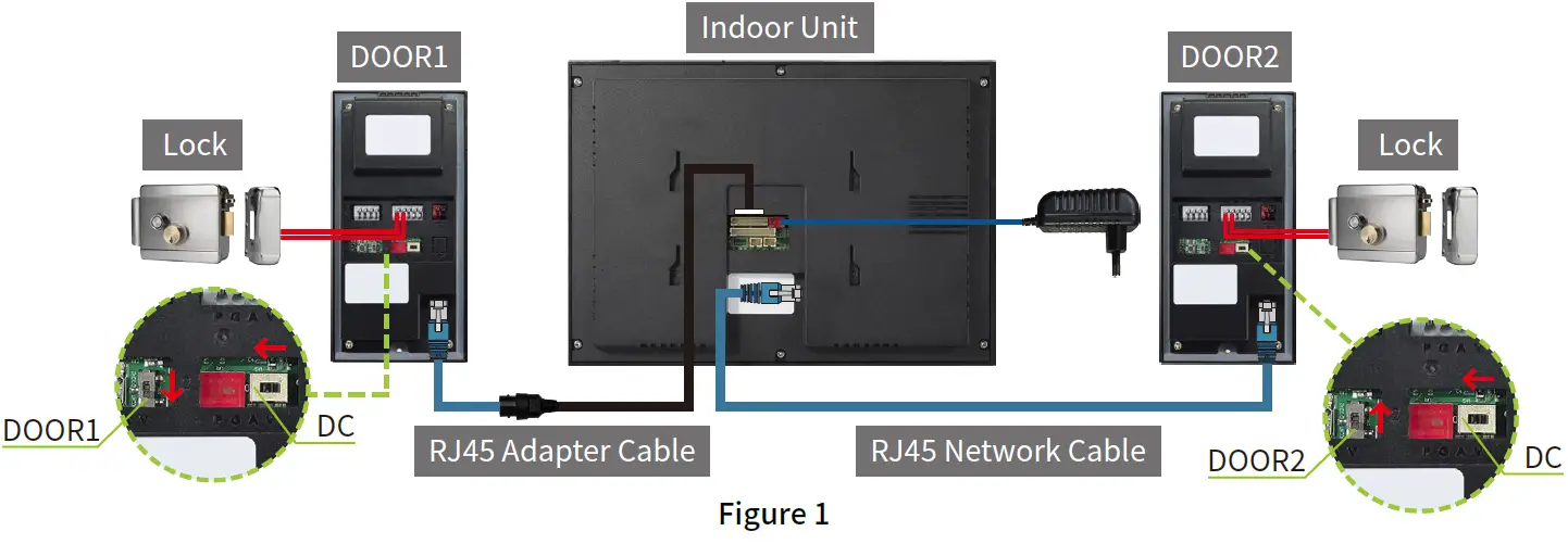
Direct Connection Wiring Diagram
National Standard POE Switch Network Wiring Diagram
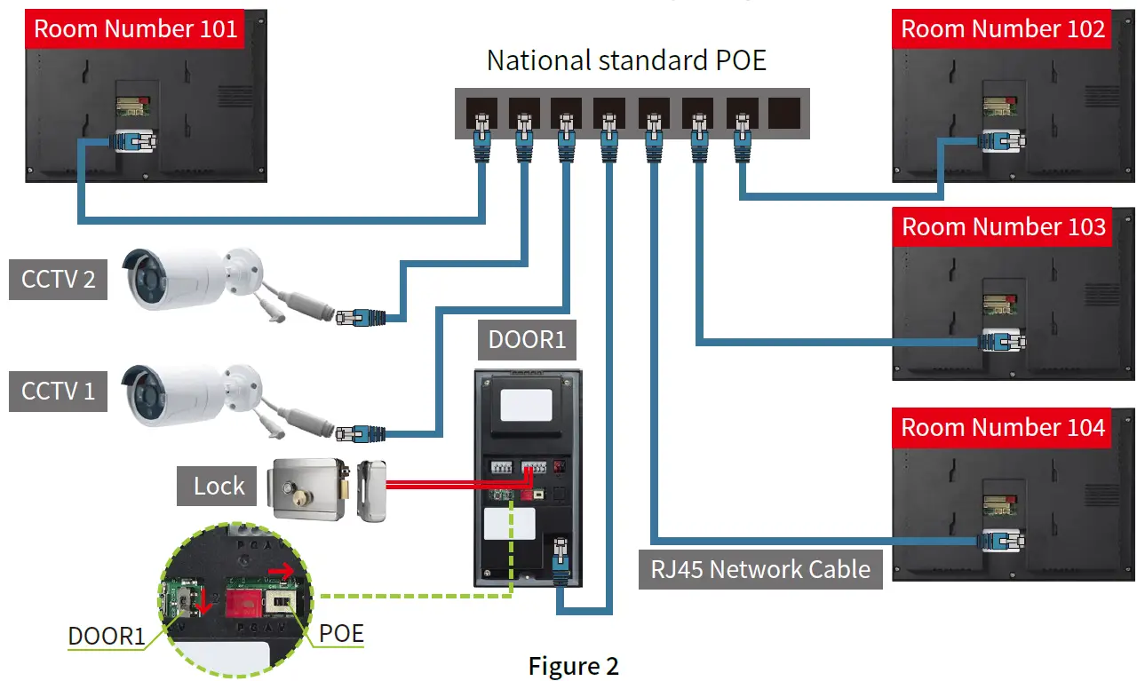
Notes
- The diagram indicates that one call button on the outdoor unit can control up to four indoor units, with no more than four indoor units. When a visitor calls the outdoor unit, all four indoor units ring simultaneously.
Dual Outdoor Unit Networking Wiring Diagram
Notes
- As shown in Figure 3, when two outdoor units are connected, they need to be set as DOOR1 and DOOR2 respectively. The call buttons (1-4 buttons) of the two outdoor units correspond to each other. Regardless of calling the call button of DOOR1 or DOOR2, the specified indoor unit will ring;
- As shown in Figure “101”, the user has installed 4 indoor units. When a visitor calls, all 4 indoor units ring simultaneously. This feature requires setting the floor/extension numbers of the indoor units;
- The floor number indicates the call button of the corresponding outdoor unit, which is set to “1” in the figure;
- The extension number indicates that when multiple indoor units are connected and need to ring at the same time, the indoor unit extension numbers are arranged from 01 to 04, which are set as “01-04” in the figure.
Setup Path: Settings → Other → Advanced Settings (initial password 1234) – Device Information → Floor Number/Extension Number

Wiring Diagram for Electric Lock Control

Notes:
- The lock is controlled by the electric lock icon ”
 ” on the indoor unit monitoring interface.
Wiring Diagram for Exit Button and Access Control Power Supply

Notes:
- The lock on this access control power supply is controlled by the garage lock unlock icon ”
 ” on the indoor unit monitoring interface;
 - The exit button controls the lock connected to this access control power supply.
Doorbell Button Wiring Diagram

Notes:
- The indoor unit is connected to the doorbell button. When a visitor presses the doorbell, the indoor unit will ring without switching to the surveillance screen; the duration of the ring is determined by the length of the ringtone.
- When the indoor unit is set to Home or Away mode, the indoor unit will ring when a visitor presses the doorbell. When set to Sleep mode, the indoor unit will be silent and not ring.
Quick Start Guide
Home Screen Function Introduction
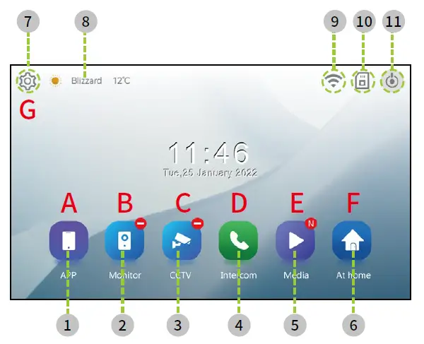
- Call Mobile APP
- Monitoring
- CCTV
- Intercom
- Browse
- Scene Mode
- Settings
- Weather Forecast
- WiFi Status
- TF Card Status
- Standby
APP
Function Path: Home Screen → APP

- This device supports the indoor unit calling and speaking with the mobile end (Tuya Smart App). To use this feature, please ensure that your indoor unit is connected to the network and paired with the Tuya Smart App.
- Please refer to the Wi-Fi setup to complete the network configuration and follow the tutorial to pair it with the app.
Notes:
- This function can only initiate a call from the indoor unit to the mobile end (Tuya Smart App)
Monitor
Function Path: Home Screen → Monitor

- ➀. Switch Monitoring Interface
- ➁. Garage Lock
- ➂. Answer Call
- ➃. Electric Lock Control
- ➄. Video Recording
- ➅. Take Photo
- ➆. Return to Higher Level
- ➇. Display Recording Method
- ➈. Display TF Card Presence
- ➉. Monitoring Countdown
- ⑪. Trigger Alarm
- ⑫. Basic Adjustments
Basic Adjustments
Access the adjustment menu by clicking on any area of the screen
Function Path: Monitoring/Unanswered Calls & Answering Calls → Tap on Any Area of the Screen → Adjust Values

- ⑫. Adjust Screen Brightness
- ⑬. Adjust the Ring Volume for Calls from the Outdoor Unit
- ⑭. Adjust the Volume for Intercom Received by the Indoor Unit
- ⑮. Adjust the Volume for Intercom Received by the Outdoor Unit
- ⑯. Call Transfer (Only Possible with Indoor Units on the Same Floor Number)
CCTV
From the home screen, tap the CCTV button to enter the CCTV monitoring interface, where the indoor unit’s screen will display the live feed from CCTV?/?.
Function Path: Home Screen → CCTV

- Switch CCTV Monitoring Interface
- Video Recording
- Take Photo
Intercom
When connecting multiple indoor units in series, you need to set the room numbers to achieve intercom calls. The dialing duration is 30 seconds, and the call duration is 60 seconds. By entering the correct room number of the indoor unit, you can call that indoor unit. The format is “101”, where the first “1” represents the floor, and the last “01” represents the room number. Room numbers can range from “101” to “104”.
Setup Path: ➀Configuration → ➁General→➂Advanced Settings(Enter the initial password ????) →➃Device Information→ ➄Set Floor NO./Extension NO.

Function Path: Home Screen → Intercom

- Enter the room number “104” for the indoor unit you wish to call internally → Tap the green button to make the call.
- Upon receiving an internal call, you can choose to answer or hang up the call.
Media
- Record motion detection recorded files, automatically recorded files, and manually recorded files.
Scene Mode
This feature has a total of 3 icons:

- Home Mode: Normal operation mode. When a visitor calls the outdoor unit, both the indoor unit and the outdoor unit will ring.
- Away Mode: When a visitor calls the outdoor unit, it plays a voice prompt “Please leave a message after the beep,” and the indoor unit will be silent and not ring.
- Sleep Mode: When a visitor calls the outdoor unit, it will ring, and the indoor unit will be silent and not ring.
- When auto-recording video or taking photos is set, if a visitor calls the outdoor unit, the system will automatically record the event.
Configuration

- I. Recording
- II. Wi-Fi
- III. Volume
- IV. General
Recording
Auto Recording
- You can choose between photo mode and video mode. Once this function is enabled, the system will automatically record when a visitor calls the outdoor unit.
- The indoor unit system has an internal storage capacity of 5MB, which only supports photo mode and can be used without a TF card. If you need to use video recording, you must insert a TF card.
Message Time
- When the indoor unit is set to Away Mode, upon a visitor calling the outdoor unit, the outdoor unit will play a voice prompt for leaving a message.
- After the prompt is finished, the system will start automatically recording video. The recording duration can be adjusted and ranges from 30 to 120 seconds.
Recent Calls
- Record the time when a visitor calls the outdoor unit and the status of whether the call is answered or not.
Motion Detection
- Select Camera: Refers to choosing the device (Outdoor Unit ?/?) that will trigger motion detection.
- Storage Method: Refers to selecting the way the system automatically records (photo capture or video recording).
- Sensitivity Settings: Refers to the sensitivity level for triggering motion detection, with options for high, medium, or low.
- Turn on Screen During Motion Detection: If this feature is not enabled, the system will record video or capture snapshots in the background when motion is detected, and the indoor unit screen will not light up. If this feature is enabled, the indoor unit screen will light up, displaying the real-time image from the outdoor unit, while the system records video or captures snapshots.
Notes:
- A TF card is required to use the video recording function.
Loop Monitoring
- The system will cycle through monitoring the connected outdoor unit and CCTV, with the duration of monitoring for each set between (10 to 60 seconds). During this process, the indoor unit screen will remain on in monitoring mode, and video can be recorded or snapshots captured.
Notes:
- When only one outdoor unit or CCTV is connected, the system will repeatedly cycle through monitoring that device.
Wi-Fi
The indoor unit needs to be connected to a properly functioning WiFi network (hereinafter referred to as WiFi). Complete the connection according to the following steps:
1 Turn on the wireless switch and select the WiFi to connect to → 2 Enter the correct password for the WiFi and tap to connect → 3 Wait for the connection → * Complete the connection → 5 Return to the home screen to check the network status → 6 Then tap on the WiFi QR code.

Download and register the Tuya App
- For iOS system: Search for “Tuya App” in the “Apple Store” and download it;
- For Android system: Search for “Tuya App” in the “Google Play Store” and download it.
- Or use the phone’s scanning feature to scan the QR code below and select the corresponding country to download.
- After completing the account registration, log in.

- Users can choose to log in with a mobile number/email /QQ account/WeChat using various methods.
Create a home group operation

- Open the Tuya App Tap on ➀ “My” Select ➁ “Home Management”
- Tap on ➀ “Create a Home”

- Create ➀ “Home Name” by selecting “City Location” ➁ Choose any room location,Click Save, then click Complete.
- Return to the home page and tap on ➀ “Home”➁ Tap on “Home Management” in the top left corner and select the “Home Name” you just created.

- At this point, the home group has been successfully created.
Mobile phone Tuya App pairing operation
Method One (Search for “Add Device”)
Notes: During the pairing process, the phone and the indoor unit must be connected to the same WiFi network to use the add device feature for searching and pairing.

- Tap on ➀ the top right corner“+ ”, and select “Add Device”.
- The system automatically searches for nearby devices that can be added. When the device is discovered, tap ➀ to add it.

- Connecting to the device, please wait.
- Connection completed, device added successfully, tap ➀ “Done” to automatically jump to the monitoring screen.
Method Two (Scan QR Code to “Add Device”)

- Tap on ➀ the top right corner“+”, and select “Scan”.

- Point your phone’s camera at the activated Tuya QR code on the indoor unit to scan it.

- The phone enters the network pairing mode, waiting for the network to be paired.
- Connection completed, device added successfully, tap ➀ “Done” to automatically jump to the monitoring screen.
Volume
Door 1/2 Ring
- You can set three different time periods to control the ring volume, call ringtone, and the duration of the ring.
Loop Monitoring
- It indicates the voice prompt when the garage lock and electric lock are activated.
General
LOT Settings
- English, Chinese, Arabic, Russian, French, German, Portuguese, Spanish, Italian.
Language
- Weather Forecast: When the phone is connected to the Tuya App and this feature is enabled, the home screen will display the current weather conditions for the area in real time;
- Mobile Message Push:Refers to enabling push notifications, when a visitor calls the outdoor unit, the system will push the call information to the mobile phone’s Tuya Smart App;
- Delay Notification:Refers to the duration for which incoming call push notifications are sent to the mobile phone’s Tuya Smart App, with a default of ? seconds and a range of ? to ?? seconds;
- Network Connection:The default setting is for WLAN (Wireless Local Area Network) connection. If the Wi-Fi signal is poor, it can be switched to a cable (Wired Local Area Network) connection;
- UUID:Display the device ID number.
Advanced Settings
Advanced Settings(Initial password 1234)
Device Information: Floor NO and Extension NO
- Floor NO:The range “1-4” refers to the corresponding call buttons of the outdoor units (DOOR1/DOOR2).
- If an outdoor unit needs to call multiple indoor units with a single call button, the floor numbers of the indoor units should be set to the same number, as shown in (Figure 3).
- If an outdoor unit needs to call a single indoor unit with one call button, the floor numbers of the indoor units should be set to different numbers, as shown in (Figure 3).
- Extension NO:When connecting multiple indoor units in series, the extension numbers should be arranged in sequence, such as “01-04”. If only one indoor unit is connected, it is set to “1” by default.
Doorbell Settings
- Gate Unlock Time: Set the lock opening time to between 1 second and 60 seconds, during which the lock will remain unlocked;
- Door Unlock Time: Set the lock opening time to between 1 second and 10 seconds, during which the lock will remain unlocked;
- Gate Lock Detection: This feature detects whether the door lock is closed and can set a duration for closing. If the lock is already closed, the door lock icon will change from open to closed. If the lock is still open, the door lock icon will turn red and display a “Door Not Closed” notification.
Card Swiping Settings (ID Card Quantity: 50 cards)
- You can choose to register an ID card for the desired outdoor unit 1/2 by adding it.
- Tap the ” + ” to add a card. The system prompts to swipe the card. Place the ID card on the outdoor unit’s card swiping area for identification. The outdoor unit beeps twice to indicate successful recognition. Automatically recognizes the card number, click confirm, and complete the addition.

Notes
- The card number is the identity information of the ID card, which is silk-screened on the ID card when manufactured. The system will read this card number for entry, and you need to manually use a notebook to register the card number and the corresponding user name for later card management;
- You can click the delete button to remove unwanted cards, and deleted cards will not be able to unlock the door.
CCTV Manage
Wired Connection
- Properly connect the IP camera to the POE switch, click the ” + ” to search for devices, select wired connection, and the system will search for connectable devices;
- Click on the IP camera that needs to be connected;
- Enter the account (admin) and password for the IP camera, and click refresh;
- Select a video stream and click register, then choose to set it as CCTV? or CCTV?, and complete the setup.

Wireless Connection
- To connect a wireless IP camera, both the camera and the indoor unit should be connected to the same Wi-Fi network.
- Click the ” + ” to search for devices, select wireless connection, and the system will search for connectable devices.
- Click on the IP camera that you wish to connect.
- Enter the account (admin) and password for the IP camera, and click refresh.
- Select a codec stream and click to register, then choose to set it as CCTV1 or CCTV2 to complete the setup.

Security Setting

- Each indoor unit can be connected to a maximum of 8 alarm sensors.
- (Note: The alarm sensor should be correctly connected to the indoor unit. You need to check and correctly configure the sensor type as NO/NC in the settings menu.)1
Alarm Trigger
- When the sensor triggers an alarm, the following page will be displayed, and the monitor will continue to transmit an alarm sound.

- Enter the security password (default 1234) to disarm the alarm.

- When to activate the sensor: Security sensors can operate in “Home/Away/Sleep” modes.
- Each individual sensor can be set up, allowing you to edit its status (activate/disable), name, working mode (NC/NO), and the alarm delay when the sensor is triggered (0-90 seconds).
- You can view and delete records of triggered sensors.
Quick Setting Sync
- With this feature, you can quickly share the settings of bound CCTV and security configurations to other indoor units without the need for individual configuration.
Notes:
- Only the extension indoor units can obtain setting data from the main indoor unit; the settings of both the main indoor unit and the extension indoor units can be shared.
Security Password
- Change the password required to access advanced settings to any four-digit code of your choice.
System Time
You can manually set the system time or connect the indoor unit to a WIFI network, and connect it to the smartphone Tuya app. After restarting the indoor unit, the system will automatically synchronize the time from the smartphone app to the extension units on the same floor number. If you are in surveillance view or video view, the synchronization will not be performed for that indoor unit.
System Reset
- When the indoor unit is restored to factory settings, the system will automatically restart, and the system will automatically unbind from the associated smartphone Tuya app.
Reboot
- Restart the indoor unit’s screen.
Version
- Software Version Number.
FCC STATEMENT
This equipment has been tested and found to comply with the limits for a Class B digital device, pursuant to part 15 of the FCC Rules. These limits are designed to provide reasonable protection against harmful interference in a residential installation. This equipment generates, uses and can radiate radio frequency energy and, if not installed and used in accordance with the instructions, may cause harmful interference to radio communications. However, there is no guarantee that interference will not occur in a particular installation. If this equipment does cause harmful interference to radio or television reception, which can be determined by turning the equipment off and on, the user is encouraged to try to correct the interference by one or more of the following measures:
- Reorient or relocate the receiving antenna.
- Increase the separation between the equipment and receiver.
- Connect the equipment into an outlet on a circuit different from that to which the receiver is connected.
- Consult the dealer or an experienced radio/TV technician for help.
Caution: Any changes or modifications to this device not explicitly approved by the manufacturer could void your authority to operate this equipment.
This device complies with part 15 of the FCC Rules. Operation is subject to the following two conditions:
- This device may not cause harmful interference
- This device must accept any interference received, including interference that may cause undesired operation.
The device has been evaluated to meet general RF exposure requirement This equipment complies with FCC radiation exposure limits set forth for an uncontrolled environment.
This equipment should be installed and operated with minimum distance 20cm between the radiator & your body.
Documents / Resources
 | Xinsilu 2AZKV-IP IP Smart Wi-Fi Video Intercom System [pdf] Instruction Manual 2AZKVIP, 2AZKV-IP IP Smart Wi-Fi Video Intercom System, 2AZKV-IP, IP Smart Wi-Fi Video Intercom System, Smart Wi-Fi Video Intercom System, Wi-Fi Video Intercom System, Video Intercom System, Intercom System, System |