![]() UDP6730 Series Digital Control Power Supply
UDP6730 Series Digital Control Power Supply
User’s Manual
UDP6700-DC Digital Control Power Supply
Perface
Thank you for purchasing this brand new product digital control power supply. In order to use this product safely and correctly, please read this manual thoroughly, especially the safety notes.
Copyright Information
Copyright is owned by Uni-Trend Technology (China) Co., Ltd.
UNI-T products are protected by patent rights in China and other countries, including issued and pending patents.
Uni- Trend reserves the rights to any product specification and pricing changes.
Uni-Trend Technology (China) Co., Ltd. all rights reserved. Trend reserves all rights. Information in this manual supersedes all previously published versions. No part of this manual may be copied, extracted or translated by any means without the prior permission of Uni Trend.
UNI-T is the registered trademark of Uni Trend Technology (China) Co., Ltd.
Warranty Service
The instrument has a warranty period of one year from the date of purchase. If the instrument is damaged due to improper operation by the user during the warranty period, the maintenance fee and the costs caused by the maintenance shall be borne by the user, and the instrument shall be maintained by the company for life.
If the original purchaser sells or transfers the product to a third party within one year from the date of purchase of the product, the warranty period of one year shall be from the date of the original purchase from UNI-T or an authorized UNl-T distributor. Power cords, accessories and fuses, etc. are not included in this warranty.
If the product is proved to be defective within the warranty period, UNI-T reserves the rights to either repair the defective product without charging of parts and labor, or exchange the defected product to a working equivalent product (determined by UNI-T). Replacement parts, modules and products may be brand new, or perform at the same
specifications as brand new products. All original parts, modules, or products which were defective become the property of UNI-T.
The “customer” refers to the individual or entity that is declared in the guarantee. In order to obtain the warranty service, “customer “must inform the defects within the applicable warranty period to UNI-T, and perform appropriate arrangements for the warranty service.
The customer shall be responsible for packing and shipping the defective products to the individual or entity that is declared in the guarantee. In order obtain the warranty service, customer must inform the defects within the applicable warranty period to UNI-T, and perform appropriate arrangements for the warranty service. The customer shall be responsible for packing and shipping the defective products to the designated maintenance center of UNIT, pay the shipping cost, and provide a copy of the purchase receipt of the original purchaser. If the products is shipped domestically to the purchase receipt of the original purchaser. If the product is shipped to the location of the UNI-T service center, UNI-T shall pay the return shipping fee. If the product is sent to any other location, the customer shall be responsible for all shipping, duties, taxes, and any other expenses.
Limited Warranty and Liability
The warranty is inapplicable to any defects, failures or damages caused by accident, normal wear of components, use beyond specified scope or improper use of product, or improper or insufficient maintenance. UNI-T is not obliged to provide the services below as prescribed by the warranty:
a) Repair damage caused by installation, repair or maintenance of personnel other than service representatives of UNI-T;
b) Repair damage caused by improper use or connection to incompatible equipment;
c) Repair any damages or failures caused by using power source not provided by UNI-T;
d) Repair products that have been changed or integrated with other products (if such change or integration increases time or difficulty of repair).
The warranty is formulated by UNI-T for this product, replacing any other express or implied warranties. UNI-T and its distributors refuse to give any implied warranty for marketability or applicability for special purpose. For violation of the warranty, repair or replacement of defective products is the only and all remedial measure UNI-T provides for customers.
No matter whether UNI-T and its distributors are informed of any possible indirect, special, occasional or inevitable damage in advance, they assume no responsibility for such damage.
Safety Information
![]() Warning
Warning ![]() Caution:
Caution:
To avoid possible electric shock and personal safety problem, please follow the instructions below.
| Disclaimer | Please read the following safety information carefully before starting to use the instrument. Uni-Trend will not be responsible for the personal safety and property damage caused by the user’s failure to comply with the following terms. |
| Instrument Grounding | To prevent the risk of electric shock, please connect the power ground wire. |
| Operating voltage | Please make sure operating voltage under rated range of 10%, to avoid damage the instrument. |
| Input voltage | Please use AC 110V~220V 50/60Hz AC power supply, use national approved power cord and make sure insulating layer is in good condition. |
| Inspecting the wire of the instrument | Inspecting the condition of the insulating layer of the wire, check if it is broken, bareness or workable. If the wire is damaged, please replace it before connect with the instrument. |
| Fuse wire of the instrument | Only allowed use the dictated specification fuse wire. |
| Over-voltage protection | Please make sure the instrument is not over-voltage(such as the voltage caused by thunder. To prevent operating personnel away from electric shock. |
| Do Not open the cover when the instrument is in operating | Please do not operating the instrument when open the cover and do not change the internal circuit. |
| Do Not touch live part | When the instrument is in operating, do not touch the bare connect wire, spare input terminal and the circuit is in testing. When the instrument is over DC 60V or AC 30V, be careful electric shock. |
| Do Not use the instrument in an explosive atmosphere | Do not use the instrument in flammable and explosive gas, steam or dusty environment. The use of any electronic equipment in such an environment is a risk to personal safety. |
Safety Mark
| Grounding | On (Power) | ||
| Protective Grounding | Off (Power) | ||
| Signal Ground | Connect with Cabinet or Case | ||
| Dangerous Mark |
Environment-friendly Use Period![]() EFUP is the period of time before any of the RoHS substances are likely to leak out, causing possible harm to health and the environment. EFUP of this instrument is 40 years, it should be recycling system when exceed 40 years.
EFUP is the period of time before any of the RoHS substances are likely to leak out, causing possible harm to health and the environment. EFUP of this instrument is 40 years, it should be recycling system when exceed 40 years.
Waste Electrical and Electronic Equipment (WEEE) Directive 2002/96/EC![]() Must not be discarded in the trash can.
Must not be discarded in the trash can.
Product Series
UDP6730 Series Digital Control Power has two models, UDP6730 and UDP6731.
Output range as follows,
| Model | Output Range |
| UDP6730 | 0-40V,0-30A, 0-360W |
| UDP6731 | 0-80V,0-15A, 0-360W |
Characteristics
- Fully digital control
- High resolution 10mV/1mA
- Low ripple and noise
- Software calibration
- Smallest outline
- High-definition LCD display
- Remote Sense compensaton
- Support RS-232 communication
- Intelligent fan regulation
- Rated voltage and current output·
- High-reliability: OVP(over voltage protection)/OCP(over current protection)/OTP(over temperature protection)
- Output on/off control
- High performance-price ratio
- Storage for 3×200 preset voltage and current output
Basic Performance
UDP6730/UDP6731 digital control power supply with widest voltage and current range, it can applied in many fields.
Take UDP6730 for example, with max power 360W and output adjustable in 40V/30A, auto control voltage and current slew rate, power rate up to three times rapid than other similar products. One instrument can replace three models (40V×9A/24V×15A/12V×30A), save your repeat investment.
Example
Take UDP6730 for example,set output voltage as 40V, because the max power of UDP6730 is 360W, so the max output current is 360W/40V=9A. When output voltage down to 20V, the max output current turns to 360W/20V=18A. The max output current of UDP6730 is 30A, if the output voltage continue decrease , the max output current of UDP6730 still as 30A.
Specifications
| Specification | UDP6730 | UDP6731 | |
| Output Range | Voltage | 0-40V | 0-80V |
| Current | 0-30A | 0-15A | |
| Power | 360W | 360W | |
| Load Regulation | Voltage | <0.03%+15mV | <0.03%+30mV |
| Current | <0.03%+30mA | <0.03%+15mA | |
| Power Supply Regulation | Voltage | <0.03%+15mV | <0.03%+30mV |
| Current | <0.1%+15mA | <0.1%+10mA | |
| Programming Accuracy | Voltage | <0.1%+30mV | <0.1%+10mV |
| Current | <0.3%+2mA | <0.3%+10mA | |
| Read-back Accuracy | Voltage | <0.1%+10mV | <0.1%+10mV |
| Current | <0.3%+30mA | <0.3%+10mA | |
| Ripple and Noise | Voltage | <12.0mV rms | <12.0mV rms |
| Current | <72.0mA rms | <27.0mA rms | |
| Dimension | wxHxD | 87x174x255(mm) | 87x174x255(mm) |
| Weight | Net | <2.5Kg | <2.5Kg |
Front Panel  Rear Panel
Packing List
Before use the instrument, please,
- Check whether the appearance is damaged, scratched or has other defects;
- Check with packing list to confirm that accessories has no loss.
If there have any problem, please contact with Uni-Trend Instrument Sale Department or the distributor.
| Components | Quantity | Remarks |
| The instrument | 1 | The model is subject to the actual order |
| 3C power line | 1 | |
| 250V/5A spare fuse | 2 | Only For 220Vac input. |
| Alligator pics with parallel wire | 1 | |
| User’s Manual /Upper computer software | 1 | Electronic file,download from the official website |
Requirements of Power Supply
UDP6730 series digital control power supply can only use under the power supply terms as the table below.
| Parameter | Requirements |
| Voltage | AC110/ 220(± 10%)V |
| Frequency | 50/60Hz |
| Fuse | AC220V input voltage: 250V/5A |
| Fuse | AC110V input voltage: 250V/8A |
- Factory supply three-core power cable, please make sure power cable of three phase socket is connect with ground before use.
- This instrument 220V is select fuse of 250V/5A , the specification is 5×20mm. There is one more 250V/5A fuse in fuse box before the product leave the factory.
- Please remove the external power cable before replace the fuse, open the fuse socket slot under the power supply plug, take out the old fuse and replace the new fuse into it, after that the instrument can be used normally.
![]() Warning: Do not use power cable with any signs of damage to avoid danger!
Warning: Do not use power cable with any signs of damage to avoid danger!
Operating Environment
UDP6730 series digital control power supply can only use in normal temperature and low condensing zone. The general environmental requirements of the instruments is listed as the below table.
| Operating Environment | Environmental Requirements |
| Temperature | 0℃~45℃ |
| Humidity | 20%~80%(non- condensation) |
| Storage temperature | -20℃~70℃ |
| Altitude | ≤2000 meter |
| Pollution degree | 2 |
Explanation: In order to guarantee the accuracy of measurement, it is suggested that turn on the instrument half an hour before operating.
Cleaning
To prevent from the risk of electric shock, please pull out power line before cleaning.
Please use a clean cloth dipped in clean water to clean the cover and panel.
Do not clean the inside of the instrument.![]() Caution: Do not use solvents (alcohol or gasoline etc.) to clean the instrument.
Caution: Do not use solvents (alcohol or gasoline etc.) to clean the instrument.
Quick Start
Appearance Inspection
- Check out the instrument is in a good condition during the delivery. If there have any problem, please contact with Uni-Trend Instrument Sale Department or the distributor.
- Confirm whether the AC input voltage of UDP6730/UDP6731 comply with the standards of your country or region.
Notice: Use 110V/220V switch on the rear panel to select input voltage. After confirming the above matters, power on the instrument.
Voltage Setup
- Push
 key to set voltage value;
 - Push
 or
or  to select the specific numeric field;
 - Rotating
 to enter the defined voltage parameter.
 Current Setup
- Push
 key to set current value;
 - Push or to select the specific numeric field;
- Rotating
 to enter the defined current parameter.
 Enable Output
- Push
 to enable power output function and the indicator light will be green. In the mean time, C.V/C.C indicator light will be green or red light according to the different output mode;
 - OUTPUT key indicator light will be off when OUTPUT function is disable. C.V/C.C indicator light will also be off.
 Keyboard Lock
Lock keyboard function is prevent unauthorized worker or operating personnel form making accident operation. To avoid damage the device under test.
- Push Lock key to enable lock keyboard function and the indicator light will be green. Lock symbol will shown on the top of screen.
- In lock status, long push Lock key to unlock the function and indicator light will be off. Lock symbol will also disappear on the screen.
 OVP Function
- Long push key to set OVP function;
- Push or to select the specific numeric field and enter OVP parameters;
- Push or
 to enable OVP function;
 - When the OVP function set successfully, ☑ mark will shown beside OVP parameters.
 OCP Function
- Long push key to set OVP function;
- Push or to select the specific numeric field and enter OCP parameters;
- Push or to enable OCP function;
- When the OCP function set successfully, ☑ mark will shown beside OCP parameters.
 Beep Switch
- Push
 to enter the setup interface, rotate to adjusting buzzer mode;
 - When the buzzer function is enable, keyboard sound is also turn on; when the buzzer function is disable, keyboard sound will be silent. Buzzer status will shown on the top screen.
- Push
 to exit the setup page.
 Brightness Setup
- Push to enter the setup interface;
- Push or to select Brightness field;
- Rotate to set the brightness, adjusting range 0~100%;
- Push to exit the setup page.

Memory Group Setup
- Push to enter setup interface;
- Push or to select Memory option;
- Rotate to set memory group, the maximum range is 200;
- Push to exit the setup page.

Memory Group Voltage/Current Setup
Set the specific output voltage/current point and select memory key M1~M3, push it to save the current setting.
When user need to call the stored output voltage/current, enter the setup interface to select the specific memory group and then push memory key M1~M3 to call the specific stored output voltage/current.
When user call the stored output voltage/current, the corresponding memory key will indicate green light.  Output Mode Setup
- Push to enter setup interface;
- Push or to select the output status bar;
- Rotate to select Out State;
- Output status symbol will shown on the top screen when output is finished;
- Push to exit the setup page.
Notice: When output function is operating, power supply should remain enable status. That is, ![]() should keep operating status when turn off the power supply.
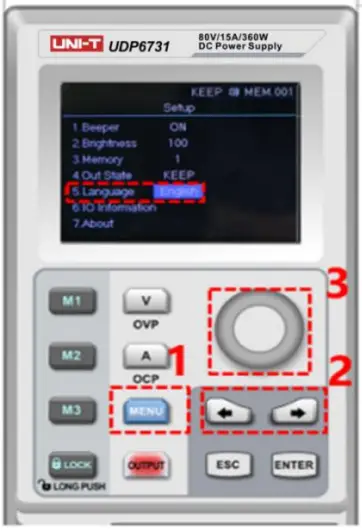
should keep operating status when turn off the power supply. 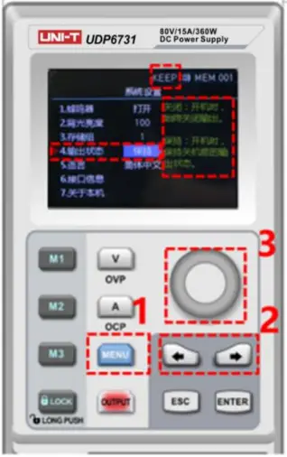 Language Setup
- Push to enter setup interface;
- Push or to select language field;
- Rotate to select Language type (English/Chinese);
- Push to exit the setup page.
 Display Interface Information
- Push to enter the setup interface;
- Use left, right arrow key to select the IO Information option;
- RS232 configuration information will shown on the right side of the screen.
 About
About
- Push to enter the setup interface;
- Push or to select About field;
- The device information product’s model and the current version number will shown on the right side of the screen.
 Remote Sense Compensation Setup
Before use Remote Sense compensation function, take off short connect terminal on the Remote Sense compensation terminal, connect load voltage positive terminal to compensation terminal S+ and load voltage negative terminal connect to compensation terminal S-. And then enable power output to turn on Remote Sense compensation function. That is, the output voltage of the DC power supply is the voltage of the load terminal.
Notice: Remote Sense compensation voltage should less than 0.9V.  CV/CC Operating Mode of Power Supply
Power supply can automatic transfer constant voltage/current function. Power supply can ongoing switch the constant voltage/current function dependent on load fluctuation.
If the current load is on the constant voltage mode, power supply provide a controlled output and voltage. As the load resistance value decreases, the output voltage remains constant until the output current increases to greater than the preset current value, which it will convert operating mode. If the power supply turn into constant current output, the output voltage will decrease proportionally according to resistance value of the load. When the current value less than the set value, power supply will back to the constant voltage mode.
Troubleshooting
Power supply is no output
- Check the set value of voltage and current is zero or not. If it is, reset the voltage and current value.
- OUTPUT indicator light is light on or not. If it is, push OUTPUT key to enable the output function.
- Check OVP,OCP,OTP function is activated or not. If it is, reset the value of OVP, OCP and wait the power supply remain stable to turn the output function.
- If Remote Sense compensation function has been enabled, check the line loss of output cable is excepted the limit value or not. If it is, replace the output cable or decrease the output current, and then try to enable the power supply again.
The keyboard is not work
Check Lock indicator light is light on or not. If it is, please refer to Lock section to reset again.
Remote Communication
The instalment and startup configuration file
- Download the instalment file from official website;
- Turn on power supply;
- Connect the control line of RS232 to control power supply;
- Activate the remote controlling application program;
- Click Shipments List, and double-click the power supply symbol of UDP6730 or UDP6731 to enter the remote communication interface.
 Remote Control Interface & Operating Instructions
List Mode (Time Function) and Delayer Mode
List Mode
List mode can setup multiple testing program, it can set 48 groups of independent ant voltage, current and parameter of output duration time.
Delayer Mode
Delayer mode can setup multiple testing program to control output status, which is set count to control output status is on or off, and the time interval of switch can also set by point to point. Delayer mode can set 48 output status groups to control parameter.
Output parameter of list/delayer mode can all store in internal storage. It has power down function. Storage space for each group is 48
Operating Steps
- Push power supply switch to turn on the instrument;
- Turn on list mode/ delayer mode: Push arrow key or to enter setup interface of list/delayer mode. It can be circular switch.
Notice:
a. List/delayer mode and channel output function can’t use at the same time, it can only choose either-or;
b. When List mode status is pause, delayer mode can’t set parameter. It should enter setup interface of list mode to switch to
to  , and the status is pause and then to set parameter;
 - Connect with load;
- Set parameter of list/delayer mode;
Please refer to section Parameter Setting of List Mode and Parameter setting of Delayer Mode. - Enable timing/delayer output;
In timing/delayer interface, rotate rotary knob to and push to enable timing/delayer output function. Symbol turn to and status bar will also change to “stop” to “run”; - Disable timing/delayer output;
In timing/delayer interface, rotate rotary knob to and push to disable timing/delayer output function. Symbol turn to and status bar will also change to “run” to “stop”;
Another shortcut to disable output function, push key to turn off timing/delayer function in any interface.
Parameter Setting of List Mode

Menu introduction of list mode
Cycle index:It divide into maximum inf and 1-999. A cycle period is start form setup origin point to end point. Push rotary knob ![]() to adjusting parameters.
to adjusting parameters.
Count: It can set “001” – “048”, which is excite group from origin point to end point. Push rotary knob ![]() to adjusting point. Notice: each voltage, current and time is a point.
to adjusting point. Notice: each voltage, current and time is a point.
Origin point: It can adjust “000”-“047”, which is start from origin point to run. (“origin point” value + “count” value ≤ 048)
Mode: It divide into three mode stop, run and pasue, it can not be set;
Pause presents power supply is not output at the current;
Run presents power supply is operating;
Pause presents power supply is paused;
Notice: In pause and run mode, interface can not be adjust; pause only shown when indicator ![]() is off and only shown on
is off and only shown on ![]() interface.
interface.  This curve figure can direct present the setting parameter of list mode.
  Table setting:serial number of each group is corresponding to voltage, current and time value, push rotary knob
 ![]() to set parameter;
to set parameter;
Voltage:adjust the actual output voltage value;
Current:adjust the current value;
Time:duration output time value in this serial number;![]() ,
, ![]() : operating status at the current, push rotary knob
: operating status at the current, push rotary knob ![]() to switch mode;
to switch mode;
Save: save the setting parameter for power down function, push rotary knob ![]() to save the current setting;
to save the current setting;![]() : clear parameter values in the table all to zero (voltage 00.00, current 00.00, time 00.00), push rotary knob to
: clear parameter values in the table all to zero (voltage 00.00, current 00.00, time 00.00), push rotary knob to ![]() eliminate the setting parameter values in the table;
eliminate the setting parameter values in the table;
Notice: clear select function is eliminate the corresponding group of origin point to count.
Parameter Setting of Delayer Mode

 It presents power output status and delayer time of user configuration,it’s convenient to view the data.
 Protection setting:this function can set protection value of voltage, current and power, push rotary knob
 ![]() select “√”to turn on protection function;
select “√”to turn on protection function;
Cycle index:It divide into maximum inf and 1-999. A cycle period is start form setup origin point to end point;
Count:It can set “001” – “048”, which is excute group from origin point to end point. Push rotary knob ![]() to adjusting parameter;
to adjusting parameter;
Origin point: It can adjust “000”-“047”, which is start from origin point to run. Push rotary knob ![]() to adjusting parameter (“origin point” value + “count” value ≤ 048) Mode: It divide into three mode stop, run and pasue, it can not set;
to adjusting parameter (“origin point” value + “count” value ≤ 048) Mode: It divide into three mode stop, run and pasue, it can not set;
Stop presents power supply is not output at the current;
Run presents power supply is operating;
Pause presents power supply is paused;
Notice:In pause and run mode, interface can not be adjust; pause only shown when protection function is enabled.  Table setting:serial number of each group is corresponding to output status and delay time, push rotary knob
 ![]() to set parameter
to set parameter
Mode:ON presents output function is enabled, OFF presents output function is disabled
Time:set the delay time of the main interface;![]() ,
, ![]() : operating status at the current, push rotary knob to switch mode;
: operating status at the current, push rotary knob to switch mode;
Save: save the setting parameter for power down function, push rotary knob ![]() to save the current setting;
to save the current setting;![]() : clear parameter values in the table all to zero (voltage 00.00, current 00.00, time 00.00), push rotary knob
: clear parameter values in the table all to zero (voltage 00.00, current 00.00, time 00.00), push rotary knob ![]() to eliminate the setting parameter values in the table;
to eliminate the setting parameter values in the table;
Notice: clear select function is eliminate the corresponding group of origin point to count.
![]() UNI-TREND TECHNOLOGY (CHINA) CO., LTD.
UNI-TREND TECHNOLOGY (CHINA) CO., LTD.
No.6, Gong Ye Bei 1st Road,
Songshan Lake National High-Tech Industrial
Development Zone, Dongguan City,
Guangdong Province, China truments.uni-trend.com
Documents / Resources
 | UNI-T UDP6700-DC Digital Control Power Supply [pdf] User Manual UDP6700-DC Digital Control Power Supply, UDP6700-DC, Digital Control Power Supply, Control Power Supply, Power Supply |


