1. Introduction
The Datakom DPR-02 is a three-phase (line to neutral) voltage protection relay engineered to safeguard electrical systems from various voltage anomalies. It provides robust protection against over voltage, under voltage, and incorrect phase rotation, making it suitable for critical applications in distribution substations, generators, motors, transformers, and compensation systems.
This device offers adjustable over and under voltage limits, along with configurable trip and reset delays, allowing for precise customization to specific system requirements. Both maximum and minimum voltage limits can be set or disabled using trimmers located on the front panel. Corresponding delay times are also adjusted via dedicated trimmers.

Figure 1: Front view of the DPR-02 Voltage Protection Controller, showing adjustment knobs and terminals.
2. Features
- DIN Rail mounted for easy installation.
- Adjustable over voltage limit (L-N).
- Adjustable under voltage limit (L-N).
- Adjustable TRIP and RESET Delays for precise control.
- Integrated phase sequence protection.
- Detection and protection against phase failure.
- Overvoltage protection.
- Protection against insufficient supply.
- 6A/277VAC relay output.
- Suitable for 1-3 phase gasoline and diesel gensets.
- Designed for front panel mounting.
- Survives cranking dropouts.
- Generator protection with built-in alarms and warnings.

Figure 2: Overview of DPR-02 features and operational principles.
3. Setup and Installation
The DPR-02 is designed for DIN rail mounting. Proper installation is crucial for reliable operation. Ensure all power is disconnected before proceeding with wiring.
3.1 Terminal Connections
The device features clearly labeled terminals for input and output connections:
- Input Terminals: N (Neutral), L1, L2, L3 (Phase voltage inputs).
- Output Relay Terminals: 1 (NC - Normally Closed), 2 (COM - Common), 3 (NO - Normally Open).
3.2 Wiring Diagram
Refer to the connection diagram below for typical wiring in a motor protection application. Ensure all connections are secure and comply with local electrical codes.
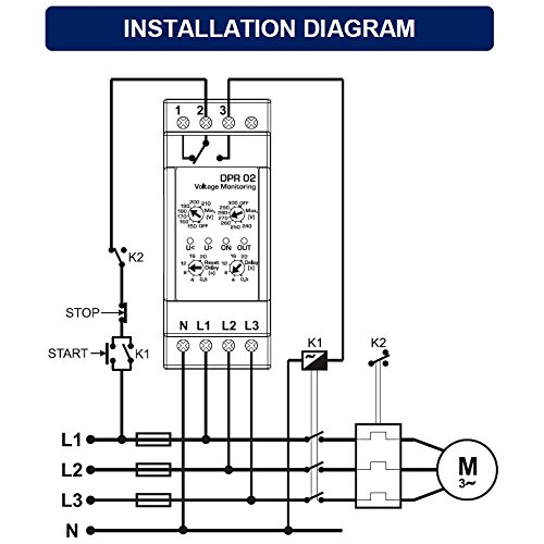
Figure 3: Typical installation diagram for the DPR-02, showing connections for a 3-phase motor.

Figure 4: Detailed connection diagram, LED indicators, and technical specifications.
4. Operating Principles
The DPR-02 continuously monitors the line-to-neutral voltages (L-N) and phase sequence to provide comprehensive protection.
4.1 Voltage Protection (Under/Over Voltage)
If any phase voltage exceeds the set MAX limit, the "U>" LED illuminates, and the adjusted Delay timer begins to count. If the fault persists beyond the delay, the relay deactivates, the "OUT" LED turns off, and the "U>" LED turns off. Similarly, if any measured voltage drops below the set MIN limit, the "U<" LED illuminates, and the Delay timer starts. If the condition persists, the relay deactivates, and the "OUT" LED turns off, and the "U<" LED turns off.
When the MAX or MIN Voltage trimmer is adjusted to the "OFF" position, the related voltage protection will be disabled.
All voltages within adjusted MIN-MAX limits will cause the "U<" and "U>" LEDs to turn off. If the adjusted Reset Delay timer counts to its expiration, the relay output is activated, and the "OUT" LED illuminates.
4.2 Phase Failure Protection
If the voltage of any phase falls below 50% of the nominal value, the "U<" LED illuminates, and the relay output immediately deactivates, turning off the "OUT" LED.
4.3 Overvoltage Protection
If the voltage of any phase goes 50% above the nominal value, the "U>" LED illuminates, and the relay output immediately deactivates, turning off the "OUT" LED.
4.4 Phase Sequence Protection
If the phase sequence is reversed, both "U<" and "U>" LEDs flash, the relay output deactivates, and the "OUT" LED turns off.
4.5 LED Indicators
The DPR-02 features several LED indicators to provide status feedback:
| U< | U> | ON | OUT | Description |
|---|---|---|---|---|
| ON | ON | ON | Voltages OK | |
| ON | ON | Under voltage warning | ||
| ON | Under voltage trip | |||
| ON | ON | Over voltage warning | ||
| ON | Over voltage trip | |||
| FLASH | ON | Phase sequence trip |
- ON: Supply LED (green)
- OUT: Relay output LED (yellow)
- U<: Under Voltage Warning LED (red)
- U>: Over Voltage Warning LED (red)
5. Maintenance
The DPR-02 is designed for long-term, reliable operation with minimal maintenance. However, periodic checks can help ensure optimal performance:
- Visual Inspection: Periodically inspect the unit for any signs of physical damage, loose connections, or excessive dust accumulation.
- Cleaning: If necessary, gently clean the exterior of the unit with a dry, soft cloth. Do not use liquid cleaners or solvents.
- Connection Integrity: Ensure all terminal connections remain tight and secure. Loose connections can lead to intermittent operation or damage.
All maintenance should be performed by qualified personnel with power disconnected.
6. Troubleshooting
If the DPR-02 is not functioning as expected, consider the following common issues:
- No Power/LEDs Off: Check the supply voltage to the N, L1, L2, L3 terminals. Ensure the power source is active and within the specified voltage range.
- Unexpected Relay Trip: Verify that the measured voltages are within the set MIN/MAX limits. Check for correct phase sequence. Review the delay settings (Trip Delay, Reset Delay) to ensure they are appropriate for the application.
- Relay Not Activating: Confirm that the input voltages are stable and within the acceptable operating range. Check the status of the U< and U> LEDs to identify any active voltage faults.
- Incorrect Phase Sequence Indication: Double-check the L1, L2, L3 phase connections for correct order.
If issues persist after checking these points, consult a qualified electrician or contact Datakom technical support.
7. Specifications
Detailed technical specifications for the Datakom DPR-02:
| Parameter | Value |
|---|---|
| Nominal Supply Voltage | 230V-AC (L-N) |
| Supply Voltage Range | 150-300 V-AC (L-N) |
| Supply Type | Capacitive, 1-phase |
| Frequency Range | 47-63Hz |
| Power Consumption | 30VA / 2W (max) |
| Measurement Method | True RMS, line to neutral |
| Voltage Adjustment Accuracy | 3 % |
| Repetition Accuracy | 0.5 % |
| Over-Voltage Trip | 240-300V-AC (L-N) adjustable |
| Under-Voltage Trip | 150-210V-AC (L-N) adjustable |
| Trip Delay Setup | 0.5 - 20 sec. adjustable |
| Reset Delay Setup | 0.5 - 20 sec. adjustable |
| Relay Output | 6A @ 277V-AC, 1800VA, 300W |
| Terminal Wire Range | 2.5 mm² (12AWG) |
| Screwing Force | 2.4 Nm (3.6 Lb) |
| Operating Temperature | -30°C (-22°F) to 70°C (158°F) |
| Storage Temperature | -40°C (-40°F) to 80°C (176°F) |
| Maximum Humidity | 95% non-condensing |
| Dimensions (WxHxD) | 36.0 x 90.6 x 58.4 mm (1.42 x 3.57 x 2.30 inches) |
| Weight | ~90 g (3.17 oz) |
| Installation | DIN Rail mounted |
| Case Material | High temp. ABS/PC (UL94-V0) |
| IP Protection | IP30 |
| Conformity (EU Directives) | 2006/95/EC (low voltage), 2004/108/EC (EMC) |
| Norms of Reference | EN 61010 (safety requirements), EN 60255-6, EN 61326 (EMC requirements) |
| Country of Origin | Turkey |
8. Warranty and Support
For information regarding product warranty, technical support, or service, please contact your authorized Datakom distributor or visit the official Datakom website. Ensure you have your product model number (DPR-02) and purchase details available when seeking support.