SPINTSO Refcom Ii Pro Units Charging Station Instruction Manual
Compliances
EU Compliances, CE
Specific Absorption Rate (SAR) certification information
The REFCOM II PRO radio is designed to not exceed the recommended limits for exposure of radio waves.
Frequency band and output power
Bluetooth BDR/EDR +7.57dBm.
Bluetooth BLE, +7.67dBm.
Declaration of Conformity
Spintso AB declares that this device complies with directive 2014/53/EU.
Visit https://www.spintso.com/declaration-of-conformity to access the declaration of conformity.
Notified Body nr.
3052
Address
Spintso AB, Övre Slottsgatan 6, 753 10 Uppsala, Sweden
European Union, Disposal information
After this product has reached end of life, it shall be taken cared of properly. Please dispose the product to the recycling facility assigned by your authorities.
UKCA
Spintso AB declares that this device complies with the relevant requirements in: The Radio Equipment Regulations 2017 (SI 2017/1206)
UK approved Body: Derycom certification services, inc., with number AB3052.
Visit https://www.spintso.com/declaration-of-conformity to access the UKCA declaration of conformity.
FCC
This device complies with part 15 of the FCC Rules.
This equipment has been tested and found to comply with the limits for a Class B digital device, pursuant to part 15 of the FCC rules. These limits are designed to provide reasonable protection against harmful interference in a residential installation. This equipment generates, uses, and can radiate radio frequency energy and may cause harmful interference to radio communications if not installed and used in accordance with the instructions. However, there is no guarantee that interference will not occur in a particular installation. If this equipment does cause harmful interference to radio or television reception, which can be determined by turning the equipment off and on, the user is encouraged to try to correct the interference by one of the following measures:
– Reorient or relocate the receiving antenna.
– Increase the separation between the equipment and the receiver.
– Connect the equipment into an outlet on a circuit different from that to which the receiver is connected.
– Consult the dealer or an experienced radio/TV technician for help.
Operation is subject to the following two conditions: (1) this device may not cause harmful interference, and (2) this device must accept any interference received, including interference that may cause undesired operation.
FCC ID: 2BBUE-R2P
General
The Spintso Refcom II Pro radio system is developed by Referees for Referees and is optimized for use in both indoor and outdoor sports environments. The system handles six users speaking in full duplex and features functionality for VAR and PA system connections.
Sections
3. Overview
4. Generic functions/features
5. Initial Preparations
6. General Handling
7. Interfaces
8. Charging cable
9. Charging Station
10. General match Set-up and handling
11. System application
12. Troubleshooting
13. Battery replacement
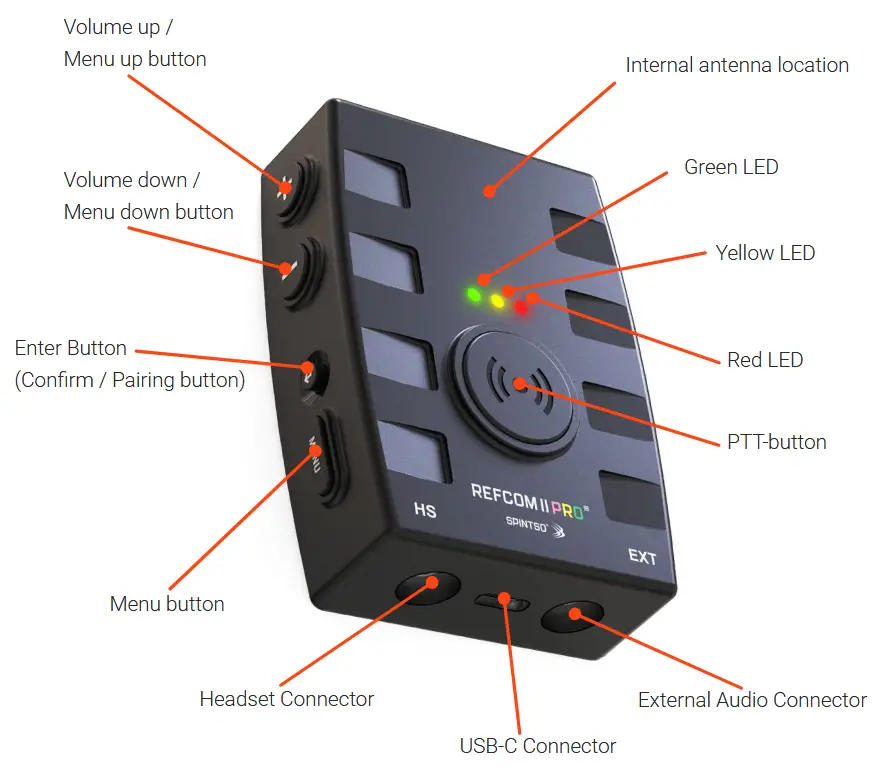
Overview
Generic functions/features
– Optimized for Referees
– Open speech conference with high performance wind & ambient noise reduction.
– Automatic whistle sound level limitation.
– Compatible with both the Spintso in-ear Swiftfit headsets and Twistlock premium headsets.
– Bluetooth 5.4 standard encryption.
– Customized high performance internal antenna solution to provide optimal range.
– 2-6 users with full duplex audio.
– Built-in Recording of the speech conference.
– Easy initial set-up by assigning each radio an individual id nr. or User Type. (1-6)
– Connects automatically at each match after power-on.
– Configurable Push to Talk button. For example used when speaking to PA system.
– External audio connector for connection of PA system, VAR, or Long range radio.
– Vibrator when used as Flag receiver.
– Extra Bluetooth Low Emission circuit for connection of Spintso Bluetooth accessories.
– License Free 2.4GHz radio band
– Battery level announcement at start-up (High, Medium, Low, Empty)
– Operational Time 12+h
– Operating Temperature -10 to + 45 °C
– Climatic environment IP54. Waterproof 3,5mm audio and USB-C connectors.
– Size: 59 x 25 x 82 mm (Including buttons)
– weight: 70g
– Future proof by SW upgrades through USB
Initial Preparations
- Charge the radios using normal USB-C or the Refcom II Pro Charging station. Red LED indicates charging, and batteries are full when the green led activates.
- Test to fit your Swiftfit Pro or Twistlock headset to your ear. If needed, change the in-ear adapters to a different size until the headset fits properly and feels comfortable.
- Mark-up the radios using the included stickers. and place the sticker on the dedicated area at the top of the unit. Choose the ones that suits your application best. In European Football it could for example be like below:

General Handling
Activation
– Radios are started up by pressing down Volume up and Volume down buttons at the same time for 2 second until the three LEDs activate.
– Radios are turned off by pressing Volume up and Volume down buttons at the same time for 2 seconds until the three LEDs activate.
Pairing
Pairing procedure is performed using the confirm button and the audio Menu.
- Connect the headsets and press the confirm button for 6 seconds on each radio until the green and red LEDs activates. This clears the pairing history and set the radios into radio pairing mode.
- Access the audio menu on each radio one at a time by pressing the MENU-button. As-sign each radio an individual number (1-6). Change number by pressing the +/- buttons. Confirm the selected number by pressing down the confirm button.
The number shall match the number on the mounted sticker.
- The pairing can be started when all radios have been set-up with their individual number. Press the confirm button for 2 seconds on the radio assigned to “RADIO 1”. All radios will pair automatically in sequence.
Note! If for example instead pressing confirm button on “Radio 2”, only the radios with higher number will be paired.
LED Indications
Radio pairing mode
Radio pairing mode state is indicated by green and red LEDs being continuously active.
Pairing
When pairing is successful, the red LED turns off and the green led indicates connected by blinking.
Connected state
a. One connected radio is indicated by a single blink.
b. Two connected radios are indicated by a double-blink.
c. At low battery, the red LED activates instead of the green.
d. The LED blinking is synchronized and moves from radio 1 to radio 6.
Not connected state
When not connected the green LED blinks 1 time per second at a 50% duty cycle.
The Yellow LED activates while Push To Talk is active. (Requires that the PTT-button is enabled)
Recording
Active recording is indicated by the red LED blinking.
Bluetooth accessory connected
A paired and connected Spintso accessory is indicated by yellow LED flashing.
Radio Connect
Connecting radios
Radios that have been previously paired, connects automatically after start-up. At connect the voice guide says CONNECT RADIO “X” on each radio.
All connected radios LEDs indicates connected mode in synchronization.
Disconnect in connected state
Disconnect only occur when out of range, or if a radio is turned off. At disconnect, the voice guide says RADIO “X” LOST on the applicable radio, and the green LED indicates accordingly.
Automatic re-connect
If radios disconnect during normal operation because of poor radio connection or by being out of range, the radios automatically re-connect when the radios are back within operational range.
Volume control
The earphone volume can be adjusted in 12 steps. Changing of the volume level is indicated by beep sounds. A high pitch beep sound indicates reaching the highest volume, and a low pitch sound indicates reaching the lowest volume. Normal and recommend- ed Volume setting is between level 7-9. (3-5 steps below maximum) If Volume feels too low from a specific user, make sure the microphone is positioned correctly.
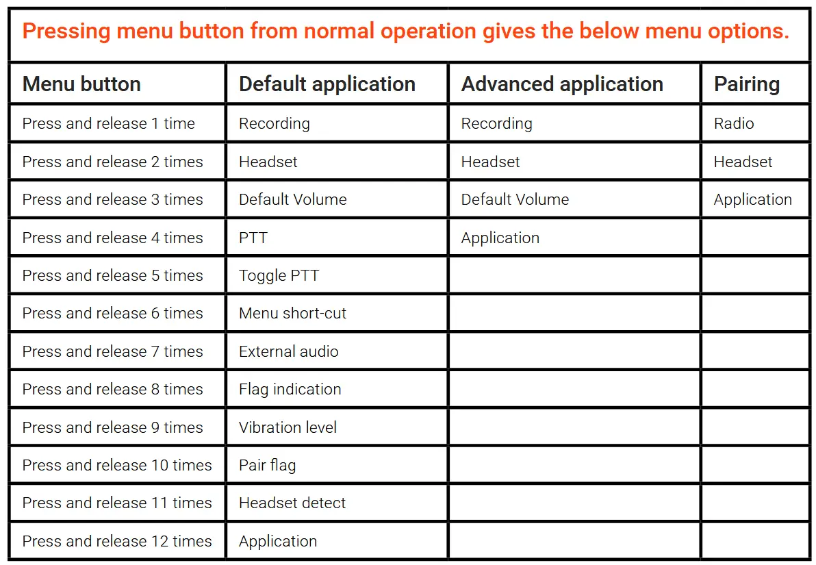
– The radio features an audio menu for setting different options. For example, selection of preferred headset model or radio number.
– Menu button is pressed to access menu mode.
– Volume buttons are used to change a setting.
– Confirmation button is used to confirm the selected setting.
– Pressing the menu button several times, steps between the menu options.
– Exit menu to normal operation i.e. Volume buttons go back to changing volume, is done after confirming a selection, or automatically after three seconds if not pressing any buttons. A selected parameter is not stored if exit menu occurs automatically after the three second time-out.
– Menu summary:
Recording [OFF, ALL, LOCAL]
– Select RECORDING ALL to record all audio the radio receives.
– Select RECORDING LOCAL to only record the microphone input.
– Select RECORDING OFF to stop the recording.
Headset [SWIFTFIT PRO, SWIFTFIT, TWISTLOCK, CLIP-MIC]
– Select the name of the headset you are connecting to the radio.
– SWIFTFIT PRO is the headset that is included in the standard set.
– Note! Setting the wrong headset can cause degraded audio performance that affects all users.
– Clip-mic users are recommended to use Push to Talk to avoid bringing annoying ambient noises into the speech conference.
Default Volume [LATEST USED, LEVEL 1-12]
– Select LATEST USED if the radio shall remember the last used volume setting at start-up.
– Select LEVEL 1-12 to have the radio always start-up on the same volume level. For example LEVEL 8.
PTT [OFF, ON, MUTE, PA DOWNLINK, PA UPLINK, LOCAL]
– Select OFF to disable the use of the radio PTT-button
– Select ON to enable the use of the radio PTT-button. When enabled the PTT-button needs to be pressed down in order to speak.
– Select MUTE to mute the microphone while pressing down the PTT-button.
– Select PA DOWNLINK to access a PA system connected to a radio with lower radio number. See PA example in applications section.
– Select PA UPLINK to access a PA system connected to a radio with higher radio number. See PA example in applications section.
– Select LOCAL to use the PTT-button for access to the external audio interface of the unit. See Long Range Radio example in applications section.
Toggle-PTT [OFF/ON]
– Note! Not applicable when PTT is set to OFF.
– Select ON to enable toggle-PTT. To activate PTT, the PTT-button is pressed and released twice within 1 second. To release PTT, the PTT-button is pressed and released once.
– Select OFF to disable the use of toggle-PTT.
– Note! Applicable for PTT setting OFF and ON.
– This feature can be enabled if there is a need to easily and swiftly change between open speech and push to talk speech.
– Select ON to use the menu-button as a shortcut to change between PTT/Normal mode, or between PTT off mode/Normal mode. Press and hold Menu-button for 2 seconds to change mode. If PTT=OFF, pressing mode enables and disables the PTT-Button. If PTT=ON pressing mode disables/enables the PTT-button.
– Select OFF to not use Menu short-cut.
External Audio [OFF, ON, LOCAL-PUBLIC, LOCAL- PRIVATE]
– Select OFF to disable the External audio interface (Ext)
– Select ON to enable the External audio interface (Ext). Audio to/from the external audio interface is enabled for all users.
– Select , LOCAL-PUBLIC to enable the External audio interface (Ext). Only the user with local-public enabled on the radio can speak to the external audio interface on his/her unit, but all users can hear the communication to/from the external interface. Requires PTT=ON
– Select LOCAL- PRIVATE to enable the External audio interface (Ext). Only the user with local-private enabled on his/her unit can speak and listen to the external audio interface. Requires PTT=ON.
Flag indication [VIBRATION, VOICE, VIBRATION AND VOICE, OFF]
– Select how the radio shall react when an assistant referee activates a Spintso electronic referee flag.
Vibration level [HIGH, MEDIUM LOW]
– Sets the intensity of the built-in vibration.
Pair Flag
– Confirm to pair a Spintso Referee flag (Pending feature)
Pair Watch
– Confirm to pair a Spintso S2 watch. (Pending feature)
Headset Detect [ON, OFF]
– Select ON to enable headset detect. Headset detect shall only be set to ON of PTT-button shall be controlled externally from the headset interface.
– Select OFF to disable headset detect.
Application [DEFAULT, ADVANCED]
– Note! All radios in the set shall be configured with the same application. Either all are configured to default, or all are configured to advanced.
– Select Default application to enable all users to speak with each other normally. Either using open speech or push to talk controlled speech. This application can be suitable in for example Football and Rugby and enables use of VAR connection. See application examples section.
– Select advanced application to enable one or two users to privately access for example a public announcement system and/or if two users need to speak with each other in a private speech conference. This application can be suitable in for example Ice Hockey, Handball, and Floorball. See application examples section.
Battery status
– When in normal operation, pressing and releasing the Bluetooth button within 2 seconds activates a battery status message.
Charging
– Charging is indicated by the red LED being active.
– Charging finished in radio off state is indicated by turning the red LED off and turning the Green LED on.
– Charging finished in radio on state is indicated by turning the red LED off. The green LED indicate status normally.
– Charging time is less than 4h.
INTERFACES
Headset
The headset interface features a waterproof 4-pole 3,5mm headset connector. It is compatible with the SPINTSO Swiftfit headset and the Spintso provided Twistlock headset.
Audio connection is according to the OMTP standard, but Ring 1 has an input detect that can activate when grounded. Ring 1 can be used for an external Push to Talk button.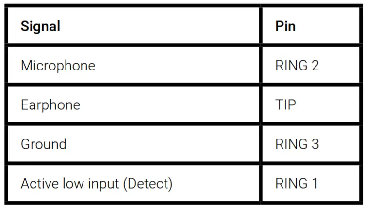
External Audio
– The external audio interface features a waterproof 4-pole 3,5mm headset connector.
– Single ended input and output Line audio with 600 Ohm impedance.
– Open Collector output that can be used for keying an external radio.
Charging & Data
The charging interface features a Waterproof USB-C connector. This interface also handles upgrades of the radio firmware.
Antenna
The radio features a calibrated internal antenna that provides optimal radio range and signal quality.
charging cable
The Refcom radios can be charged from a normal USB-C cable. The cable provides for charging and data communication. Supported feeding Voltage is 5VDC.
Charging station
– Up to six Refcom radios can be charged simultaneously by placing them in the Refcom II Pro charging station.
– Charging status is indicated on the radios themselves. Red for charging and Green for fully charged.
– Note that the radios will also indicate in Red when full and topping up the battery. This happens if the radios are left in the charger station for a long time.
– It is recommended to disconnect power to the charger station and to remove the radios from the charger station when charging is completed.

General match Set-up and handling
General
- Make sure the radios are fully charged before use.
- Start-up all radios and wait for a short moment until they have automatically connected.
- Assign each referee with the applicable radio and a headset. For example: “Radio 2, Referee 1” is handed to Referee 1.

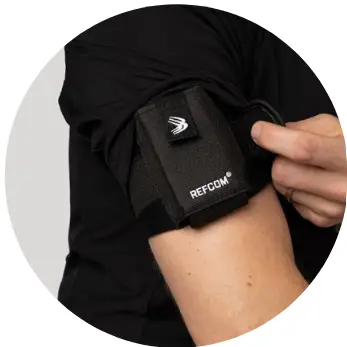
- Use SPINTSO arm-bag, waist pouch, or a shirt with dedicated arm-bag pocket when carrying REFCOM II® Pro. The radio shall preferably not be worn behind your back. The backside of the radio shall face the skin, and the connectors shall point downwards or sideways.
- Mount the headset to the ear, and make sure a secure and comfortable fitting is achieved. The microphone shall be positioned in hight with the mouth and be placed close to the cheek. Use transparent medical tape to secure the microphone position if needed.
- Adjust and attach the cable clip to the sweater collar to avoid cable tension.
- Speak between each other to check that all communication is working properly. Adjust if needed your personal earphone volume to a comfortable level. Normal and recommended Volume setting is between level 7-9. (3-5 steps below maximum) If Volume feels too low from a specific user, make sure the microphone is positioned correctly.
Set-up Headset
The headset is connected to the left connector marked with HS. Press the Menu button two times to hear which headset model that is active. Change the headset model using the menu system if wrong headset model is announced.
Set-up External
If PA or VAR is to be used, it is connected to the right-hand side connector marked with EXT.
Recording
– Select RECORDING ALL in the audio menu to record all audio the radio receives.
– Select RECORDING LOCAL to only record the microphone input.
– Activated recording is indicated by the red LED blinking.
– Select RECORDING OFF to stop the recording. The recording is then stored as a MP3-file on the radio.
– Connect the radio to a PC using a standard USB-C data cable to extract the MP3 recording file.
– Play the file using your PCs audio playing application.
SYSTEM APPLICATION
The radio system can feature two operating modes. Default and Advanced. The chosen application shall be set on all radios in the set.
On default application all users can speak to each other normally, or by pressing the push to talk button.
On advanced application, both Radio 2 and 3 can access a public announcement system connected to Radio 1. Advanced application also features open speech between only Radio 4 and 5. Speech from Radio 4 or 5 to radio 2 and 3 requires pressing down the push to talk button.
Default application examples
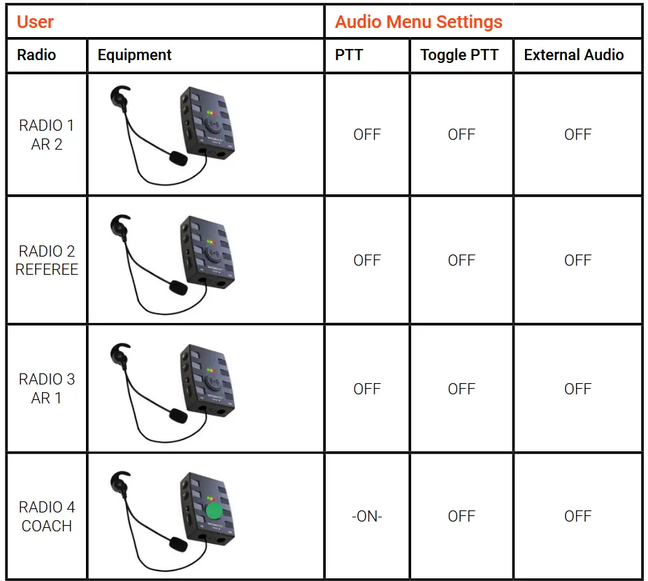
Football / Rugby Union, 3 Referees and coach
Open communication. The coach needs to press PTT-button to speak.
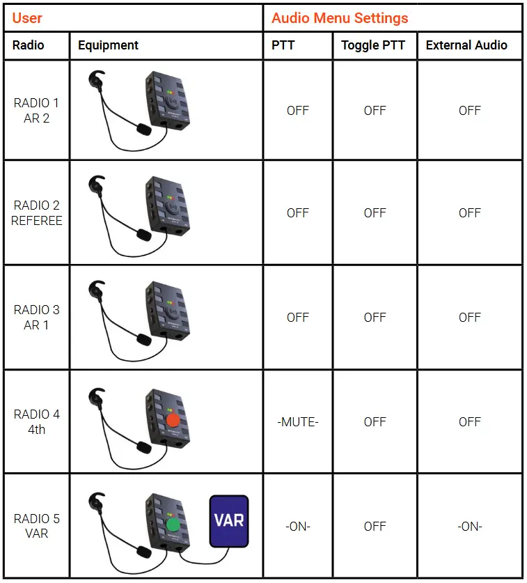
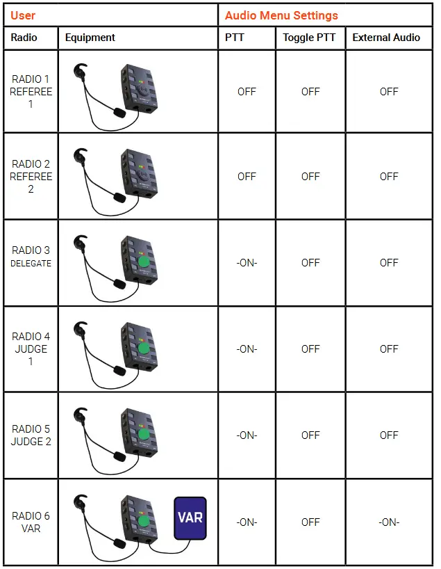
Football / Bandy, 4 Referees with VAR
Open communication. 4th can mute the microphone by pressing down the PTT-button. VAR can be local by using the headset, or remote by connecting the External audio interface to the remote VAR connection. Local VAR needs to press PTT-button to speak.
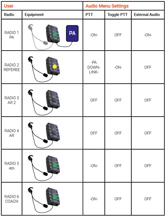
Bandy with Public Announcement (PA) and coach
Open communication. PA unit external interface connects to PA-system. The Referee user only, can access the PA system by toggle PTT. 4th and Coach need to press PTT-button to speak.
Ice Hockey, 3 Referees with Public Announcement (PA) and Supervisor
Open communication. PA unit external interface connects to PA-system. The Referee user only, can access the PA system by toggle PTT. Supervisor need to press PTT-button to speak.
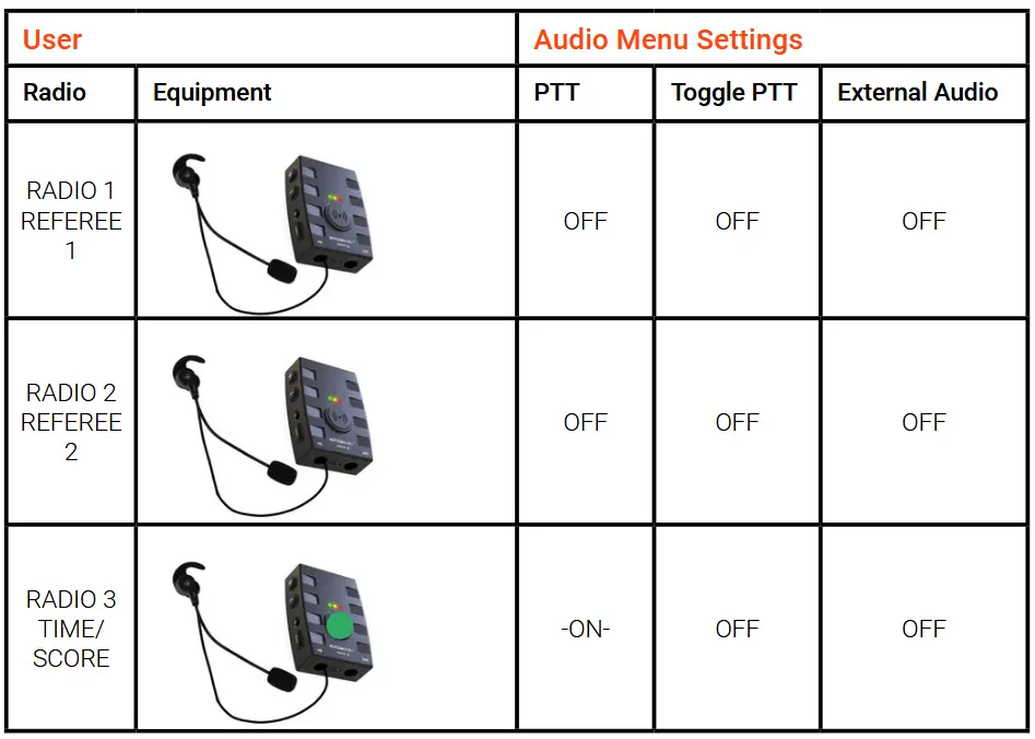
Handball / Floorball / Futsal
Open communication. The Time/Score user needs to press PTT-button to speak.
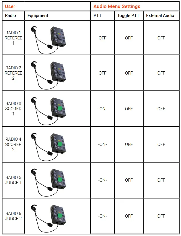
Volleyball, 6 users
Open communication. The Scorers and Judge users need to press PTT-button to speak.
Waterpolo, 6 users
Open communication. The Delegate, Judges and VAR users need to press PTT-button to speak. VAR can also be remote by connecting the External audio interface to the remote VAR connection.
Advanced application examples
Note that PTT and External Audio settings are pre-set and cannot be changed in the Audio Menu.
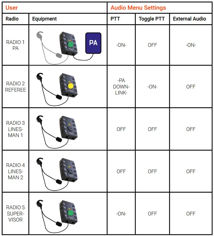
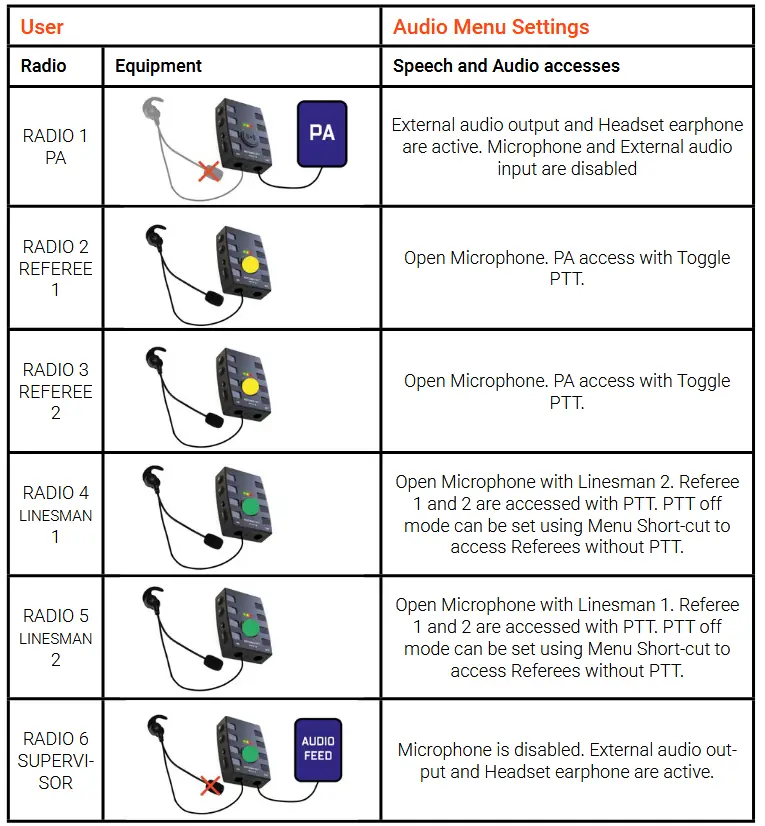
Ice Hockey, 4 Referees with Public Announcement (PA) and Supervisor
Open communication with private speech conference. PA unit external interface connects to PA-system. Only the referees can access the PA system by toggle PTT. Linesmen can speak open with each other and need to press PTT button to speak with the referees. Supervisor can only listen to the referees and linesmen. The external connector of the supervisor unit can be used to extract all speaking audio.
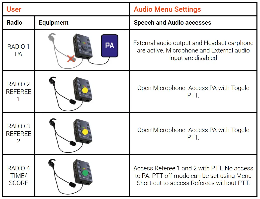
Handball, Floorball with Public Announcement (PA) and Scorer
Open communication. PA unit external interface connects to PA-system. Only the referees can access the PA system by toggle PTT. Time/Scorer user need to press PTT button to speak with the referees
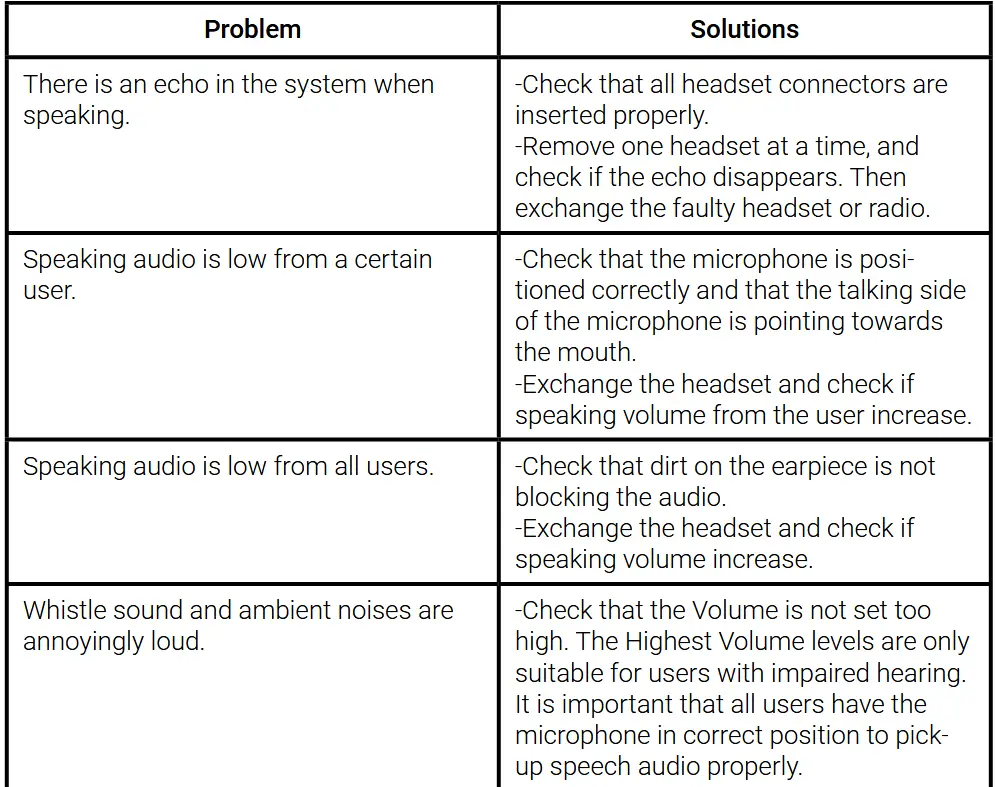
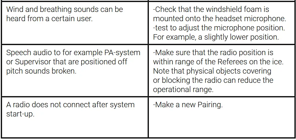
Troubleshooting
Battery replacement
There are two options to handle a change of the battery. Contact SPINTSO to have the battery exchanged for you, or exchange the battery yourself by ordering a spare battery from Spintso.
How to replace the battery
– Make sure the radio is turned off, and that nothing is connected to the radio USB-C and Audio ports.
– Disassemble the back lid by removing the six screws. Use a standard small Philips screwdriver for this and turn counterclockwise.
– Detach the lid from the housing, and make sure to not stretch the internal wires.
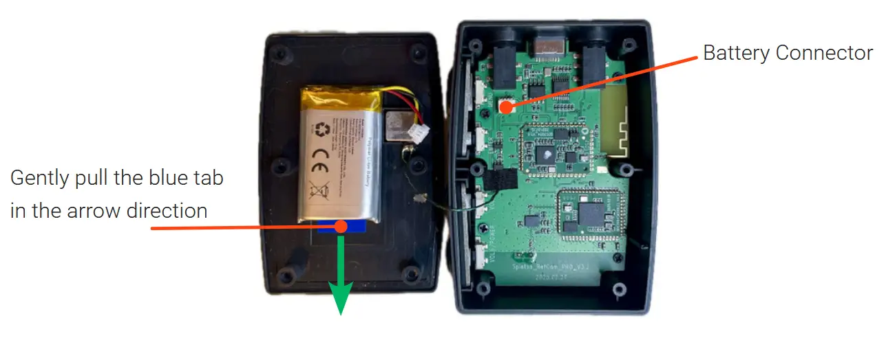
– Disconnect the battery from the circuit board battery connector and place the parts on a steady surface according to the picture below.
– Carefully and slowly pull the tab of the removable double adhesive tape strip until the battery falls off.
– Remove the tape protection of the new battery and mount it to the Lid in the same position as the old battery.
– Press and hold the battery for a few seconds to make sure it sticks to the lid properly.
– Gently connect the new battery to the battery connector on the circuit board. Note that the connector will only fit in one direction.
– Place the lid on the table with the battery facing upwards. Check that the sealing gasket is in its correct position. Mount the unit to the lid and make sure you have a good fit.
– Turn the radio with lid around and insert the six screws. Make sure to not use too much force when tightening the screws. When a small resistance is felt, and there is no gap between the lid and unit, the tightening is ok.
Documents / Resources
 | SPINTSO Refcom Ii Pro Units Charging Station [pdf] Instruction Manual 220933365-0a8a7d, Refcom Ii Pro Units Charging Station, Refcom Ii Pro, Units Charging Station, Charging Station, Station |