SONOFF ZBM5-1C-120W Zigbee Smart
Wall Switch User Manual

Introduction
This device is a Zigbee-based smart wall switch, which allows for either neutral required mode or no neutral required mode wiring, depending on your home’s circuit setup. Used with a SONOFF Zigbee gateway, you can achieve remote control of device opening/closing, setting schedule/timer, creating smart scenes, and other smart control methods.


Button
- Single press: Turn on/off the smart device
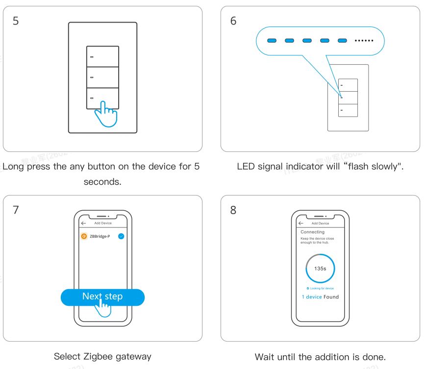
- Press and hold for 5 seconds: Device enters the pairing mode. (Pairing time 180s)
LED indicator (Blue)
- Slow flash: Device is in pairing mode.
- Fast flash Network connection abnormality
- Flashes 3 times: Wiring mode switched successfully
Compatible Voice Assistants

Specification


This product is only suitable for safe use at altitudes below 2000m.
Installation
- Power off

⚠ WARNING
Please install and maintain the device by a professional electrician. To avoid electric shock hazards, do not operate any connection or contact the terminal connector while the device is powered on! - Wiring instruction
To ensure the safety of your electrical installation, it’s essential either a Miniature Circuit Breaker (MCB) or a Residual Current operated Cicuit-breaker with Integral Overcurrent protection(RCBO) with an electrical rating of 10A has been installed before the ZBM5-1C-120W, ZBM5-2C-120W, ZBM5-3C-120W.


Choose no neutral required mode or neutral required mode according to your home’s wiring.
In no neutral required mode: the minimum supported load is 3W, and this device does not support other types of inductive loads such as fans.
Make sure all wires are connected correctly.
Instructions for wiring symbols

3. Power on
After powering on, the device will enter the pairing mode defaulted during the first use and the ” ” LED signal indicator will flash slowly .
It takes 10 seconds for the device to work normally after being powered on for the first time.

The device will exit the pairing mode if you do not operate it within 3mins. When you want to enter the pairing mode again, long press the any button on the device for 5 seconds until the
” signal light flashes slowly” and release.
Download the eWeLink App & Add SONOFF Zigbee Gateway
Please download the “eWeLink” App from Google Play Store or Apple App Store.

Scan QR Code to Add the Device
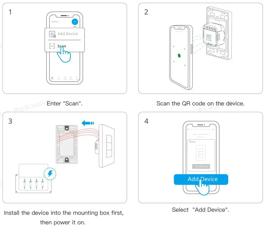
Install the device into the mounting box first, then power it on.
(It takes 10 seconds for the device to work normally after being powered on for the first time.)
Compatible SONOFF Gateways
Recommended SONOFF gateway models: ZBBridge-P (V2.2.0), ZBBridge-U (V1.6.0), NSPanel Pro (V3.7.0), iHost (V2.5.0)
Before adding a device, please upgrade the gateway firmware to the latest version. Other compatible SONOFF gateway models: ZBDongle-P, ZBDongle-E
Factory Reset
Trigger conditions (any one condition met)
- Press and hold the device button for 5 seconds
- Delete the device on eWeLink
Switch Wiring Mode
When the device is powered on for the first time, it will automatically enter either no neutral required mode or neutral required mode based on the actual wiring setup. Different modes have varying compatibility with loads. If you need to switch wiring methods, such as changing from neutral required mode wiring to no neutral required mode wiring, follow the steps below to switch the device mode:
- Choose one of the following methods to restore the device to its factory settings:
Press and hold any button on the device for more than 5 seconds Delete the device in the eWeLink app - After disconnecting power and reconnecting, the device’s signal indicator (blue) will flash three times.
Once the above steps are completed, wait for 10 seconds before the device can function properly. Add the device to the gateway again, and it will switch to the corresponding mode based on the new wiring setup.
Differences Between No Neutral Required and Neutral End Device Required Modes
No Neutral Required Mode:
The device functions as a Zigbee end device, and the external load has a minimum power requirement, with a minimum load of 3W. In this mode, smart lights are not supported, including but not limited to dimmable, color-changing, gradient, and lights with built-in controllers, as well as light strips.
Neutral Required Mode:
The device functions as a Zigbee router, enhancing the robustness and coverage of the Zigbee network in the use environment. This mode has fewer restrictions on external load, with no minimum power requirement. Smart lights are supported in this mode and can be used with the eWeLink app’s “Detach Relay” function.
Troubleshooting Guide and FAQs
- Why does the light bulb light up slightly or flicker after turning off the light?
This issue only occurs in the no neutral required wiring mode and may be caused by the following two factors: (1) The device is in neutral required mode, but the actual wiring is no neutral. You can check this fault via the app reminder. In some special cases, the product’s operating mode may not switch correctly. For example, if the device was previously operating in neutral required mode but the wiring is changed to no neutral required without resetting the device, it may not switch to the correct mode. Solution: Reset the device according to the ‘Switch Wiring Mode’ section above.
(2) The external bulb has insufficient power or is incompatible. In no neutral required mode, the minimum power requirement for external bulbs is 3W. Therefore, the connected bulb must be at least 3W. Even if the bulb power meets 3W, it does not necessarily mean that it is compatible.
No neutral required mode supports most major lighting brands, but bulbs from lesser-known or knockoff brands may cause issues, such as flickering or device malfunction, due to their internal circuit design and materials. Please choose carefully.
Solution: Replace the bulb with a brand-name bulb with a power rating of 3W. - For multi-channel products, when the A channel bulb is turned on,
why does the B channel bulb, which is in the off state, light up slightly or flicker?
This problem is also caused by incompatible or poor compatibility of the bulbs used. It may be caused by the A channel bulb or the B channel bulb, and the latter is more likely. - What types of bulbs are supported, and what is the compatibility range?
The support and requirements for bulbs are as follows.
Incandescent Bulbs: 2400W@240V MAX (per channel or total), 1000W@100V MAX (per channel or total), minimum of 3W (for no neutral required mode only). LED/CFL/Fluorescent Bulbs: 400W@240V MAX (per channel or total), 200W@100V MAX (per channel or total), minimum of 3W (for no neutral required mode only).
For older fluorescent tubes with starters, replace the starter with an electronic one to avoid potential switch damage.
FCC compliance statement
- This device complies with part 15 of the FCC Rules. Operation is subject to the following two conditions: (1) This device may not cause harmful interference, and (2) This device must accept any interference received, including interference that may cause undesired operation.
- Changes or modifications not expressly approved by the party responsible for compliance could void the user’s authority to operate the equipment.
Note: This equipment has been tested and found to comply with the limits for a Class B digital device, pursuant to part 15 of the FCC Rules. These limits are designed to provide reasonable protection against harmful interference in a residential installation. This equipment generates, uses, and can radiate radio frequency energy and, if not installed and used in accordance with the instructions, may cause harmful interference to radio communications. However, there is no guarantee that interference will not occur in a particular installation. If this equipment does cause harmful interference to radio or television reception, which can be determined by turning the equipment off and on, the user is encouraged to try to correct the interference by one or more of the following measures:
–Reorient or relocate the receiving antenna.
–Increase the separation between the equipment and receiver.
–Connect the equipment into an outlet on a circuit different from that to which the receiver is connected.
–Consult the dealer or an experienced radio/TV technician for help.
FCC Radiation Exposure statement: This equipment complies with FCC radiation exposure limits set forth for an uncontrolled environment. This equipment should be installed and operated with minimum distance of 20 cm between the radiator and your body. This transmitter must not be co-located or operating in conjunction with any other antenna or transmitter.
EU Declaration of Conformity
Hereby, Shenzhen Sonoff Technologies Co., Ltd. declares that the radio equipment type ZBM5-1C-120W, ZBM5-2C-120W, ZBM5-3C-120W is in compliance with Directive 2014/53/EU. The full text of the EU declaration of conformity is available at the following internet address: https://sonoff.tech/compliance/
For CE Frequency
EU Operating Frequency Range: Zigbee: 2405-2480MHz
EU Output Power:
Zigbee 10dBm
WEEE Disposal and Recycling Information
![]() WEEE Disposal and Recycling Information All products bearing this symbol are waste electrical and electronic equipment (WEEE as in directive 2012/19/EU) which should not be mixed with unsorted household waste. Instead, you should protect human health and the environment by handing over your waste equipment to a designated collection point for the recycling of waste electrical and electronic equipment, appointed by the government or local authorities. Correct disposal and recycling will help prevent potential negative consequences to the environment and human health. Please contact the installer or local authorities for more information about the location as well as terms and conditions of such collection points.
WEEE Disposal and Recycling Information All products bearing this symbol are waste electrical and electronic equipment (WEEE as in directive 2012/19/EU) which should not be mixed with unsorted household waste. Instead, you should protect human health and the environment by handing over your waste equipment to a designated collection point for the recycling of waste electrical and electronic equipment, appointed by the government or local authorities. Correct disposal and recycling will help prevent potential negative consequences to the environment and human health. Please contact the installer or local authorities for more information about the location as well as terms and conditions of such collection points.
Warning
Under normal use of condition, this equipment should be kept a separation distance of at least 20 cm between the antenna and the body of the user.

![]()
Manufacturer: Shenzhen Sonoff Technologies Co., Ltd.
Address: 3F & 6F, Bldg A, No. 663, Bulong Rd, Shenzhen, Guangdong, China
ZIP code: 518000
Service email: support@itead.cc
Website: sonoff.tech
![]()
Made in China
Documents / Resources
 | SONOFF ZBM5-1C-120W Zigbee Smart Wall Switch [pdf] User Manual ZBM5-1C-120W, ZBM5-2C-120W, ZBM5-3C-120W, ZBM5-1C-120W Zigbee Smart Wall Switch, ZBM5-1C-120W, Zigbee Smart Wall Switch, Smart Wall Switch, Wall Switch |
 | SonoFF ZBM5-1C-120W Zigbee Smart Wall Switch [pdf] User Manual ZBM5-1C-120W, ZBM5-2C-120W, ZBM5-3C-120W, ZBM5-1C-120W Zigbee Smart Wall Switch, ZBM5-1C-120W, Zigbee Smart Wall Switch, Smart Wall Switch, Wall Switch, Switch |