VLOGiC V5-CIC-F-PNP Intelligent Solution Interface
FAQs
Q: Can I use this product while driving?
A: By law, watching moving pictures while driving is prohibited. This product should only be used while standing or displaying fixed menus or rear-view camera video when the vehicle is moving.
Product Features
- Own on-screen display and setup
- Rear-view camera input
- Automatic switching to rear-view camera input on the engagement of reverse gear from all operation modes
- Front camera input / SMART-LINK input
- Control of SMART-LINK module over iDrive control panel
- Manual switching to rear-view camera (only for vehicles with PDC button)
- Manual return from rear-view and front camera (cancellation of automatic switching)
- 2 trigger outputs (+12V max. 1A), separately adjustable switching events (CAN, ACC, camera, reverse gear)
- Picture-in-picture mode combining after-market rear-view and front camera picture(s) with factory parking sensor graphics
- Compatible with all factory video accessories (e.g. rear-view camera, Top-View, night vision, DVD-changer, TV tuner)
- USB update port for software updates by consumer
Legal Information
By law, watching moving pictures while driving is prohibited, the driver must not be distracted. We do not accept any liability for material damage or personal injury resulting, directly or indirectly, from the installation or operation of this product. This product should onlybe used while standing or to display fixed menus or rear-view-camera video when the vehicle is moving, for example, the MP3 menu for DVD upgrades.Changes/updates of the vehicle’s software can cause malfunctions in the interface. We offer free software updates for our interfaces for one year after purchase. To receive a free update, the interface must be sent in at its own cost. Labor costs for and other expenses involved with the software updates will not be refunded.
Prior to installation
Read the manual prior to installation. Technical knowledge is necessary for installation. The place of installation must be free of moisture and away from heat sources.
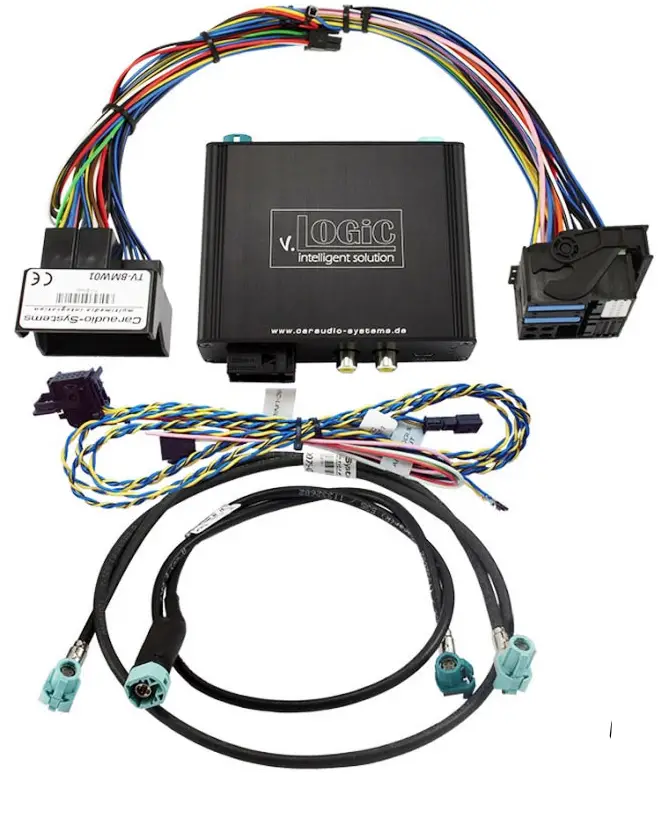
Delivery contents
Take down the SW-version and HW-version of the interface boxes, and store this manual for support purposes.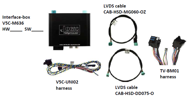
Check the compatibility of the vehicle and accessories
Requirements
Navigation
F-series with a navigation system or radio with 7“, 8.8” or 10“ monitor (F-series) with 4pin HSD LVDS connector
Note
”PDC – picture in picture” function is only for 8.8” and 10“monitors available
Setting the DIP switches of the interface box V5C-M636
DIP 1/2/3 on the back of the interface box V5C-M636 is used to set the monitor type. The default setting is:
| Vehicle/ navigation | DIP 1 | DIP 2 | DIP 3 |
| CIC-F (F-series), 7“ monitor | ON | OFF | OFF |
| CIC-F (F-series), 8.8“ monitor | OFF | ON | OFF |
| CIC-F (F-series), 10“ monitor – version 1 | ON | ON | OFF |
| CIC-F (F-series), 10“ monitor – version 2 | ON | OFF | ON |
After each change of the DIP switch settings you have to execute a power reset of the interface-box!
LEDs of the interface box V5C-M636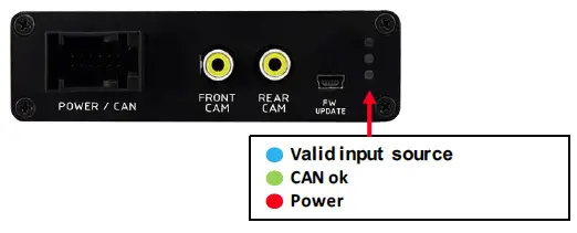
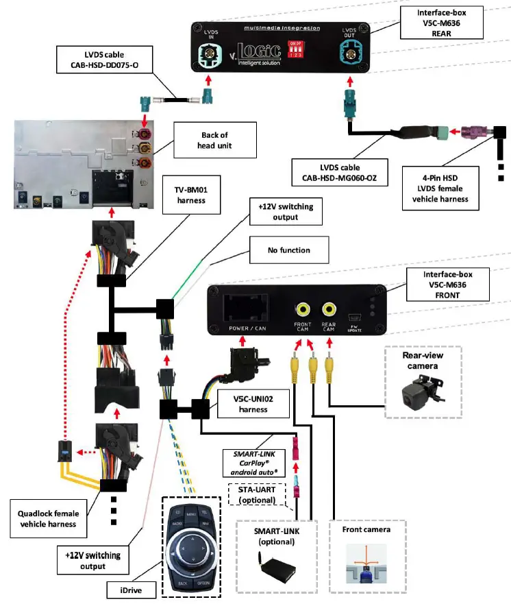
Connection schema
Installation
Switch off the ignition and disconnect the vehicle’s battery! The interface needs a permanent 12V source. If according to factory rules disconnecting the battery is to be avoided, it is usually sufficient to put the vehicle in sleep mode. In case the sleep mode does not show success, disconnect the battery with a resistor lead. If the power source is not taken directly from the battery, the connection has to be checked for being start-up-proven and permanent. Prior to wire and device installation, we suggest connecting and testing the correct function of all after-market and factory infotainment equipment!
The interface is installed on the backside of the head unit.
Connecting interface box and harnesses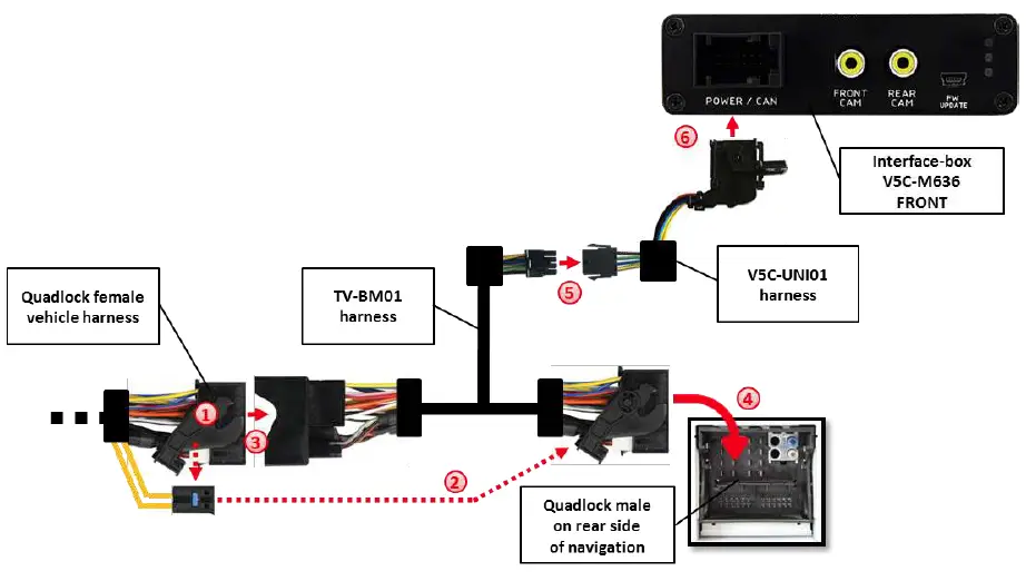
- Remove the female Quadlock connector of the vehicle harness from the rear of the navigation computer.
- Remove optical leads from the female Quadlock connector of the vehicle harness and insert them into the female Quadlock connector of harness TV-BM01 at the same position.
- Connect the female Quadlock connector of the vehicle harness to the male Quadlock connector of harness TV-BM01.
- Connect the female Quadlock connector of harness TV-BM01 to the male Quadlock connector of the navigation computer
- Connect the female 8-pin molex connector of the harness TV-BM01 to the male 8-pin molex connector of the harness TV-BM01.
- Connect the female 12pin AMP connector of the harness TV-BM01 to the front side of the V5C-M636 interface box.
LVDS connection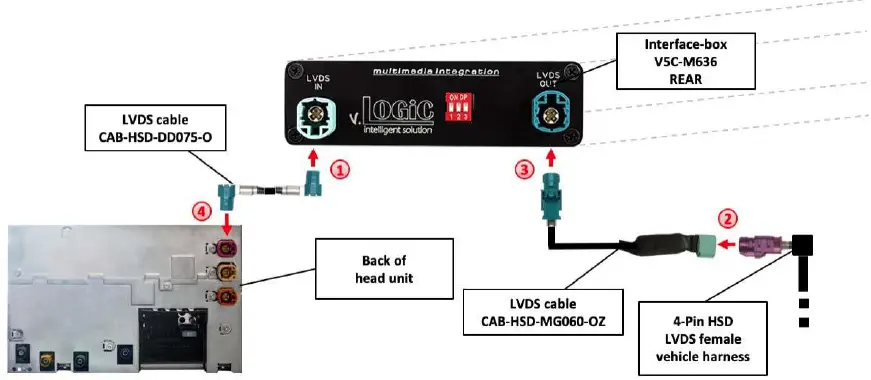
- Connect the female 4-pin HSD LVDS connector of the LVDS cable CAB-HSD-DD075-O to the male 4-pin HSD LVDS connector (LVDS-IN) on the rear of the interface-box V5C-M636.
- Remove the pink female 4-pin HSD LVDS connector of the vehicle harness at the back of the head unit and connect it to the male 4-pin HSD LVDS of the CAB-HSD-MG060-OZ LVDS cable.
- Connect the female 4-pin HSD LVDS connector of the LVDS cable CAB-HSD-MG060-OZ to the male 4pin HSD LVDS connector (LVDS-OUT) on the rear of the interface-box V5C-M636.
- Connect the female 4pin HSD LVDS connector of the LVDS cable CAB-HSD-DD075-O to the pink male 4pin HSD LVDS connector on the rear of the head unit
Connection to the iDrive
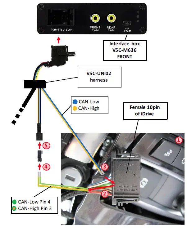
- Remove the iDrive from the center console and unplug the existing flat female 10pin or 4-pin cable connector.
- Remove pin 3 green/orange CAN-high and pin 4 green CAN-low of the vehicle harness from the female cable connector.
- Pin yellow (blue) pin of harness V5C-UNI02 into pin 3 CAN-high (pin 4 CAN-low) of the female cable connector.
- Pin the green/orange cable CAN-high (green cable CAN-low) of the vehicle harness into pin 1 of the included female 2-pin AMP connector.
- Connect female 2-pin AMP connector to 2-pin AMP connector (yellow/black and blue/black cable) of harness V5C-UNI02.
After-market front camera
Connection to the after-market front camera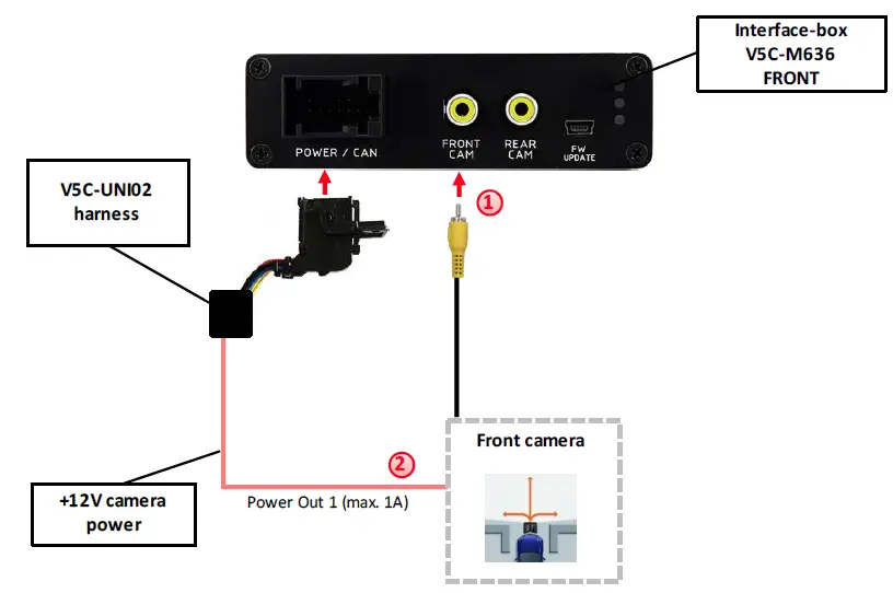
- Connect the video RCA of the after-market front camera to the female RCA connector “FRONT CAM” of the interface box V5C-M636.
- The pink wire of harness V5C-UNI02 can be used for +12V electric power supply (max. 1A) of the after-market front camera. Configure in the OSDmenu “MISC”, menu item “POWER OUT 2” the designated electric power supply (see chapter “Configurable switching outputs”).

Settings for connecting an after-market front camera
- You have to configure some settings in the OSD-menus INPUTS and MISC if you want to connect an after-market front camera (Operation of the OSD: see chapter “OSD-Operation”).

| OSD-menu | Menu item | Setting | Explication |
|
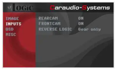
INPUTS | FRONT CAM | OFF | No front camera connected |
| ON | Switches to the front camera if the parking process is enabled and reverse gear is released | ||
|
ReverseLogic | Intelligent | For vehicles with a PDC button. Enabled while parking process and up to 20 km/h or together with PDC if existing | |
| Gear only | For vehicles without a PDC button. Enabled while parking process and up to 20 km/h. | ||
| MISC | OEM PDC CAR | Horizontal | PDC-display of the vehicle is horizontal |
| Vertical | PDC-display of the vehicle is vertical |
Note: You can deactivate the enabled parking process by pressing the iDrive or by enabling other modes (e.g. radio). After deactivation you can’t enable the parking process again until the vehicle is diving faster than 20km/h, the ignition is switched off and on or the PDC will be disabled and enabled again, if existing.
After-market rear-view camera
Connection to the after-market rear-view camera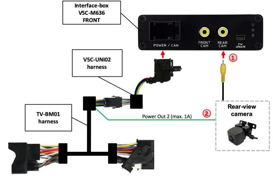
- Connect the video RCA of the after-market rear-view camera to the female RCA connector “REAR CAM” of the interface box V5C-M636.
- The green wire of harness TV-BM01 can be used for a +12V electric power supply (max. 1A) of the aftermarket rear-view camera. Configure in the OSD menu “MISC”, menu item “POWER OUT 2” the designated electric power supply (see chapter “Configurable switching outputs”).
Settings for connecting an after-market rear-view camera
- You have to configure some settings in the OSD-menus INPUTS and MISC if you want to connect an after-market rear-view camera (Operation of the OSD: see chapter “OSDOperation”).
| OSD-menu | Menu item | Setting | Explication |
|
INPUTS |
REAR CAM | OFF | No rear-view camera connected |
| ON | Switches to rear-view camera if reverse gear is engaged and/or PDC-display is displayed | ||
| OEM | If a factory rear-view camera is existing! The interface turns off, if PDC or reverse gear is enabled and it displays the factory rear-view camera and/or PDC-display | ||
|
ReverseLogic | Intelligent | For vehicles with a PDC button. Enabled while parking process and up to 20 km/h or together with PDC if existing | |
| Gear only | For vehicles without a PDC button. Enabled while parking process and up to 20 km/h. | ||
| MISC | OEM PDC CAR | Horizontal | PDC-display of the vehicle is horizontal |
| Vertical | PDC-display of the vehicle is vertical |
Note: You can deactivate the enabled parking process by pressing the iDrive or by enabling other modes (e.g. radio). After deactivation you can’t enable the parking process again until the vehicle is diving faster than 20km/h, the ignition is switched off and on or the PDC will be disabled and enabled again, if existing.
Settings for OEM rear-view camera
| OSD-menu | Menu item | Setting | Explication |
|
INPUTS | RVC | OEM | If a factory rear-view camera is existing! The interface turns off if PDC or reverse gear is enabled and it displays a factory rear-view camera and/or PDC-display |
| Reverse Logic | Intelligent | For vehicles with PDC button. Enabled while parking process and up to 20 km/h or together with PDC if existing |
SMART-LINK
The front camera input can alternatively be used for SMART-LINK set (CarPlay® & Android Auto® module) connection. In addition, the interface has the option of controlling the connected SMART-LINK module over the iDrive control panel.
SMART-LINK video and control connection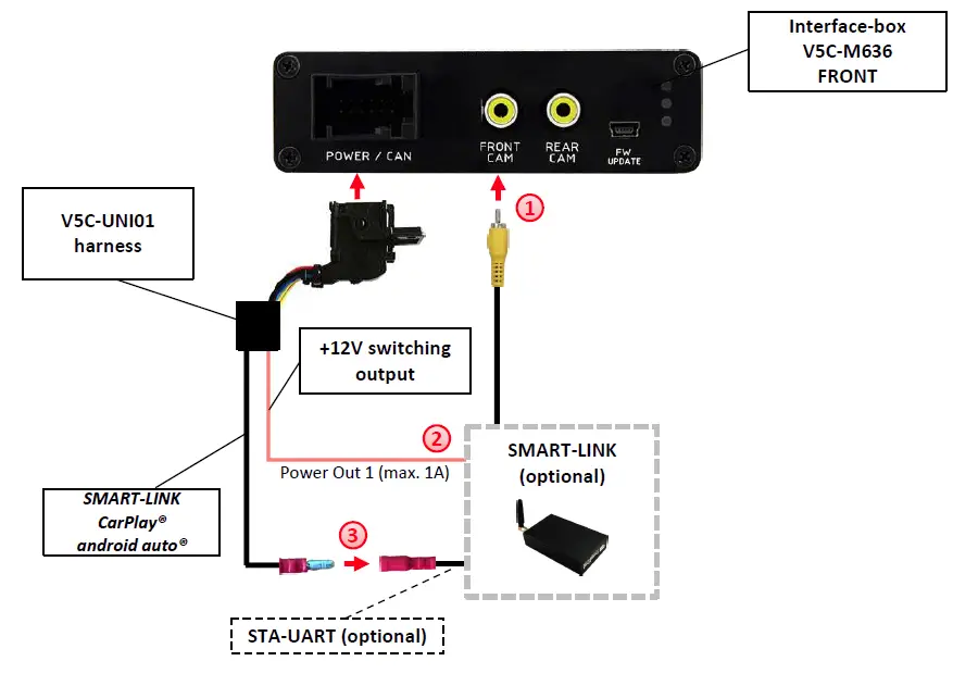
- Connect the video RCA of the SMART-LINK module to the female RCA connector “FRONT CAM” of the interface box V5C-M636.
- Connect the pink cable (+12V Power OUT 1) of the V5C-UNI01 harness to the +12V ACC power input of the SMART-LINK module. Configure inthe OSD-menu “MISC”, menu item “Power Out 1” the setting “CAN” (see also chapter “Configurable switching outputs”).
- Connect the SMART-LINK interface control port “STA-UART” (available separately) to the “SMART-LINK CarPlay® Android Auto®” socket of the V5C-UNI01 harness.
SMART-LINK audio connection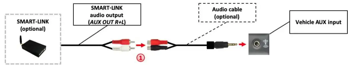
- By using an audio cable (sold separately), connect the audio output of the SMARTLINK module to the vehicle AUX input.
Settings for SMART-LINK connecting
You have to configure some settings in the OSD-menu INPUTS if you want to connect the SMART-LINK module (Operation of the OSD: see chapter “OSD-Operation”).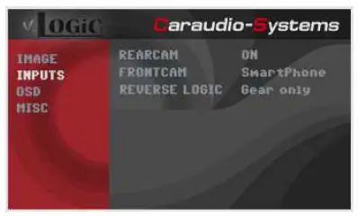
| OSD-menu | Menu item | Setting | Explication |
| INPUTS | FVC | OFF | No front camera/SMART-LINK connected |
| SmartPhone | Enables the ” FRONT CAM” input and control for the SMART-LINK set |
Configurable trigger outputs
- You can configure the both +12V trigger outputs separately. The pink wire is POWER OUT 1 and the green wire is POWER OUT 2.
Note: You can configure the both trigger outputs in the OSD-menu MISC separately (Operation of the OSD: see chapter “OSD-Operation”).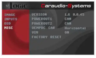
| OSD-menu | Menu item | Setting | Explication |
|
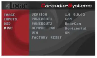
MISC |
POWER OUT1 (pink) POWER OUT2 (green) | CAN | +12V when the interface is on (red LED on) |
| Ignition | +12V when ignition is on | ||
| RearCam | +12V when the rear-view camera input is activated | ||
| Reverse Gear | +12V when the reverse gear is engaged | ||
| OFF | Trigger output deactivated |
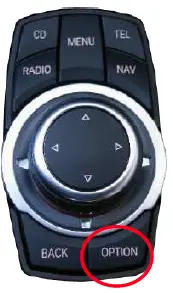
Picture settings
You can change the picture settings in the OSD-menu IMAGE (activation by long pressing the OPTION -button).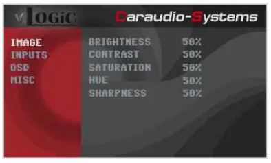
- Brightness
- Contrast
- Saturation
- Hue
- Sharpness
Note: The picture settings will be retained for each video input separately.
Picture format settings
The picture format can be changed in the SMART-LINK video level by long pressing the OPTION -button).
- 8.8” and 10.2” 24:10 ultrawide monitor:
- -FULL = 24:10 video full-screen mode
- -16:9 = 16:9 video in the center
- -AV+LVDS = 16:9 video on left side, factory picture on right side
- – 6.5” and 7” 16:9 monitor:
- -FULL = 16:9 video full-screen mode
- -ZOOM = 16:9 video full-screen mode – zoom
Operation
OSD – On-screen display
- You can change the basic configurations of the interface in the OSD (on screen display).
OSD – Operation
- You can control the OSD by Drive.
8-button Drive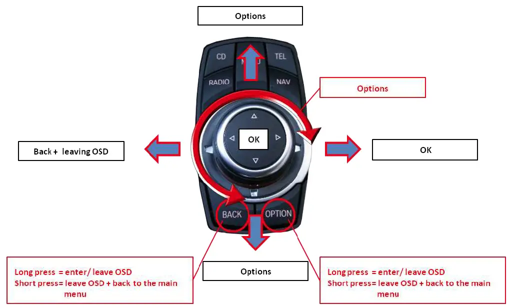
2-button iDrive in Mini
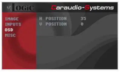
OSD – Additional setting options
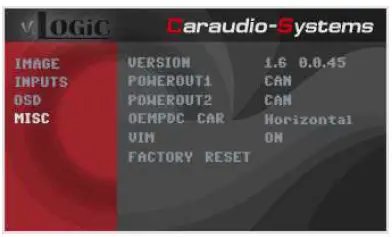
The following settings in the OSD-menus OSD and MISC can be configured over and above the described settings in this manual (Operation of the OSD: see chapter “OSD-Operation”):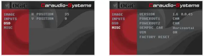
| OSD-menu | Menu item | Setting | Explication |
| H POSITION | 0-xxx | Horizontal position of the OSD | |
| V POSITION | 0-xxx | Vertical position of the OSD | |
| MISC | VERSION | X.XX.XX | Displays the current SW-version |
| FACTORY RESET | Resetting to factory settings | ||
Video-in-motion function
It is possible to activate and deactivate the video-in-motion in the OSD menu “MISC” (Operation of the OSD: see chapter “OSD-Operation”).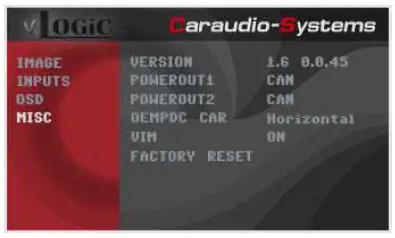
| OSD-menu | Menu item | Setting | Explication |
| MISC | VIM | ON | Video-in-motion activated |
| OFF | Video-in-motion deactivated |
For the V5-CIC-F-PNP the video-in-motion function is permanently active without disturbing the navigation performance.
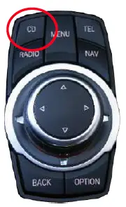
Selecting the interface as the current video source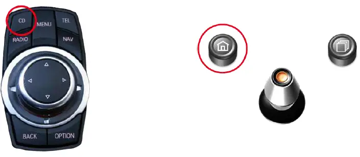
in the vehicle’s CD/Multimedia > External devices menu, activate AUX front by Drive, and after it long press the CD button to choose the interface as the current video source. Short press the CD button to switch the video inputs. Each short press will switch to the next enabled input. If all inputs are enabled the order is:
RVC → FVC/SmartPhone → …
Inputs that are not enabled are skipped. The exiting of the video interface level is achieved by long press of CD button or a short press of the RADIO / MENU / TEL / NAV button.
Note: Activation of the AUX level is not necessary for camera view.
Controlling of the connected SMART-LINK module
The picture shows which functions of the connected SMART-LINK module can be executed by iDrive control panel. Once the FVC/SmartPhone input is activated the iDrive control panel action will execute the function described in the picture.
Specifications
- Operation voltage 10.5 – 14.8V DC
- Stand-by power drain <0,1mA
- Operation power drain 190mA
- Power consumption 2,6W
- Temperature range -20°C to +80°C
- Weight (box only) 285g
- Measurements (box only) B x H x T 141 x 30 x 105 mm

Connections
(interface-box)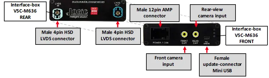
Technical Support
- CAS GmbH
- manufacturer/distribution
- In den Fuchslöchern 3
- D-67240 Bobenheim-Roxheim
- email support@casgermany.com
Legal disclaimer: The mentioned company and trademarks, as well as product names/codes are registered trademarks ® of their corresponding legal owners.
Documents / Resources
 | VLOGiC V5-CIC-F-PNP Intelligent Solution Interface [pdf] Installation Guide V5-CIC-F-PNP, V5-CIC-F-PNP Intelligent Solution Interface, V5-CIC-F-PNP, Intelligent Solution Interface, Solution Interface, Interface |