![]() p.n.560815
p.n.560815
Keypad Access Control
User Manual

Reading this manual carefully before install and use the device![]() 19 Hayezira St. Industrial Zone Ramla 7255616
19 Hayezira St. Industrial Zone Ramla 7255616
fax. 03-5214524 | phone: 03-5575110
Technical support *2023
Description
The device is a standalone access control and proximity card reader which supports EM & MF card types. It builds-in STC microprocessor, with strong anti-interference ability,high security and reliability,powerful function and convenient operation. It’s widely used in high-end buildings, residential communities and other public places.
Features
| Ultra-low Power | Standby current is less than 30mA |
| Wiegand Interface | WG26 or WG34 input and output |
| Searching time | Less than 0.1s after reading card |
| Backlight keypad | Operate easily at night |
| Doorbell interface | Support external wired doorbell |
| Access ways | Card, Pin code, Card & Pin code |
| Independent codes | Use codes without related card |
| Change codes | Users can change codes by themselves |
| Delete users by card No. | The lost card can be delete by keyboard |
Specifications
| Working Voltage: DC12-24V | Standby Current: 30mA |
| Card Reading Distance: 2 ” 5cm | Capacity: 2000 users |
| Working Temperature: -40°C-60°C | Working Humidity: 10%-90% |
| Lock output load: 3A | Door Relay time: 0-99S (Adjustable) |
Installation
Drill hole according to the size of the device and fix the back shell with the equipped screw.Thread the cable through the cable hole. connect the wires according to your required function, and wrap the unused wires to avoid short circuit. After connecting the wire, install the machine. (as show below)

Wiring
| Color | ID | Description |
| Green | DO | Wiegand Input(Wiegand Output in Card Reader Mode) |
| White | D1 | Wiegand Input(Wiegand Output in Card Reader Mode) |
| Yellow | OPEN | Exit Button input terminal |
| Red | +12V | 12V + DC Regulated Power Input |
| Black | GND | 12V – DC Regulated Power Input |
| Blue | NO | Relay normally-on terminal |
| Purple | COM | Relay Public terminal |
| Orange | NC | Relay normally-off terminal |
| Pink | BELL A | Doorbell button one terminal |
| Pink | BELL_B | Doorbell button to the other terminal |
Diagram
6.1 Common Power Supply

6.2 Special power Supply

6.3 Reader Mode

Sound & Light indication
| Operate Status | LED Light Color | Buzzer |
| Standby | Red | |
| Keypad | Beep | |
| Operation Successful | Green | |
| Beep — | ||
| Operation Failed | Beep-Beep-Beep | |
| Entering into Programming | Flash Red Slowly | |
| Beep — | ||
| Programmable Status | Orange | |
| Exit Programming | Red | |
| Beep — | ||
| Door Opening | Green | Beep — |
Advance Setting
| Add Users | Notes | |
| Change | Default factory master code is 999999. | |
| Add card |  | Cards can be added continuously |
| Add card number |  | Card number can be added continuously |
| Add ID number+ card | 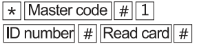 | Add user with specify ID number, easily find and delete. |
| Add ID number+ card number |  | Add user with specify ID number, easily find and delete. |
| Add PIN code |  | ID number is from 1-2000 |
| Delete Users | ||
| Delete card |  | Cards can be deleted continuously |
| Delete ID number |  | When the card is broken or lost, you can delete the user by ID number |
| Delete ALL users | Delete ALL PIN code & card users except public PIN code | |
| 3 | Access ways | ||
| By card | Only the card user could unlock the door, keypad is invalid | ||
| By card+ PIN code | To enable this function, the user PIN code has to be changed. | ||
| By card or PIN code | Both card user and PIN user could unlock the door (factory default) | ||
| 4 | Relay Output Delay Time | ||
| Door relay strike time |  | Door opening time range: 0-99s Default 5s | |
| 5 | |||
| Standalone access control mode | The door will be locked automatically after open the door normally | ||
| Relay toggle mode | The door will not be locked automatically.To lock the door, the user has to read the card or press | ||
| the exit button. | |||
| Reader mode |  | WG26/34 input and output | |
| , ° | Bind a code to a specific card |  | When using cani+code to unlock the door |
| 7 | Data backup output | Send the data to external device. | |
| Data backup input | The device will receive the data. | ||
| WiFi matching | WiFi match(optional) | ||
| 3 | Add public code |  | Only one public code is available. Delete public oxle: |
| * | Change the code by user card | |
| Change the code by ID number added |  | |
| Reset to Factory Default | Power off, press the exit button continuously, power on, hearing beep sound twice, meanwhile, the indicator light turns orange, swipe the first card as for master add card, swipe the second card as for the master delete card, the master code has been reset to 999999, factory default settings are successful. |
Master Card Operation 9.1 Add Card
Read master add card Read master add card Read the in user card Read the 2nd user card
Note: The master add card is used to add card users continuously and quickly. When you read the master add card at the first time, you will hear short “BEEP” sound twice and the indicator light turns orange, it means you have entered into add user programming. When you read the master add card at the second time, you will hear long “BEEP” sound once and the indicator light turns red, it means you have exited the add user programming.
9.2 Delete Card
Read master delete card Read the 10 user card Read master delete card Read the 2nd user card
Note: The master delete card is used to delete card users continuously and quickly. When you read the master delete card at the first time, you will hear short “BEEP” sound twice and the indicator light turns orange it means you have entered into delete user programming. When you read the master delete card at the second time, you will hear long “BEEP” sound once, the indicator light turns red, it means you have exited the delete user programming.
Data Backup Operation
Example: Backup the data of machine A to machine B The green wire and white wire of machine A connects with the green wire and white wire of machine B correspondingly, set B for receiving mode at first, then set A for sending mode, the indicator light turns green flash during the data backup, data backup is successful when indicator light turns red.
Documents / Resources
 | VisionNet 560815 Keypad Access Control [pdf] User Manual PKPR-K8, 560815, 560815 Keypad Access Control, 560815, Keypad Access Control, Access Control, Control |