TRU COMPONENTS TCN4S-24R Dual Display PID Temperature Controllers

Specifications:
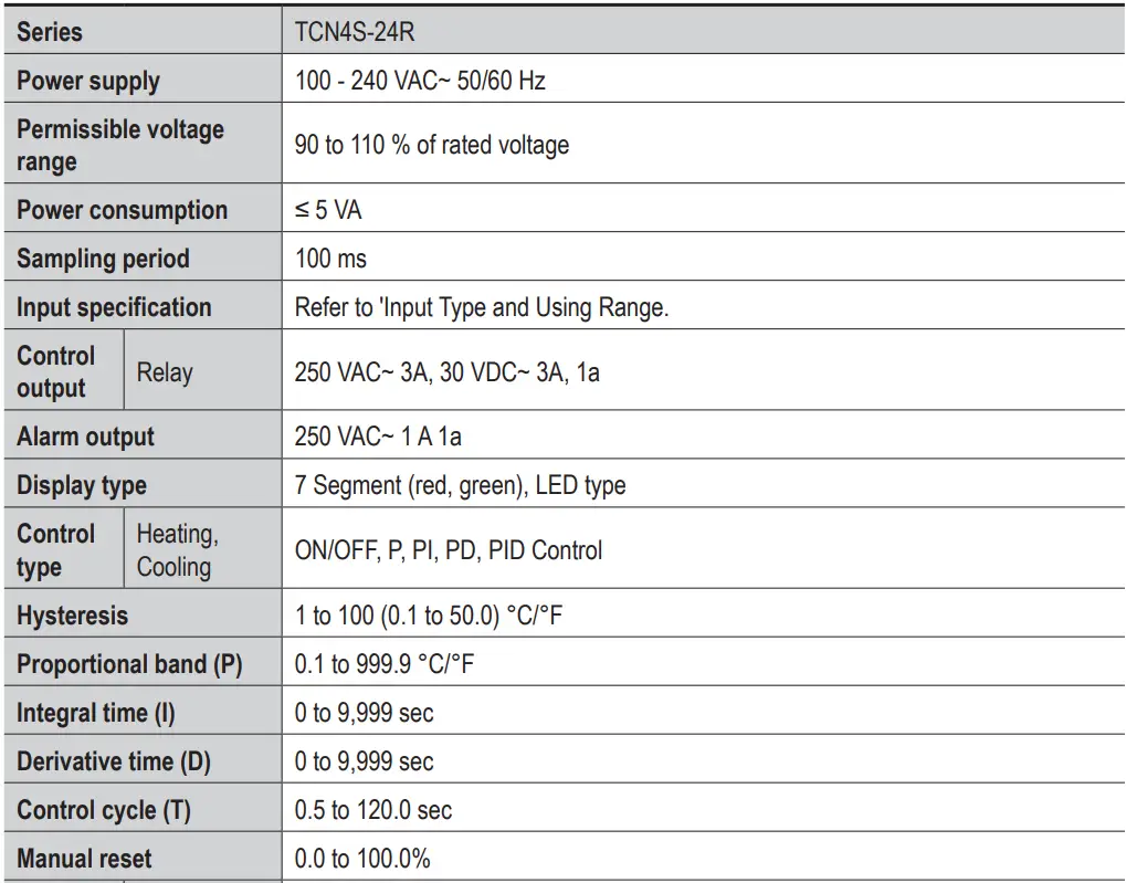
- Series: TCN4S-24R
- Power supply: AC 100-240V
- Permissible voltage range: 85-264V AC/DC
- Power consumption: Less than 5W
- Sampling period: 250ms
- Input specification: Thermocouple, RTD, linear voltage, or
linear current - Control output: Relay output
- Relay: SPST-NO (1c) / SPST-NC (1c)
- Alarm output: Relay output
- Display type: Dual display LED
- Control type: Heating/Cooling
- Hysteresis: 0.1 to 50°C or °F
- Proportional band (P): 0 to 999.9%
- Integral time (I): 0 to 3600s
- Derivative time (D): 0 to 3600s
- Control cycle (T): 1 to 120s
- Manual reset: Available
- Relay life cycle: Mechanical – 10 million operations,
Electrical – 100,000 operations - Dielectric strength: 2000V AC for 1 minute
- Vibration: 10-55Hz, amplitude 0.35mm
- Insulation resistance: More than 100MΩ with 500V DC
- Noise immunity: ±2kV (between power terminal and input
terminal) - Memory retention: Non-volatile memory retains data even when
power is off - Ambient temperature: -10 to 55°C (14 to 131°F)
- Ambient humidity: 25 to 85% RH (non-condensing)
Product Usage Instructions
Safety Considerations:
Warning:
- Install fail-safe devices when using the unit with machinery
that may cause serious injury or substantial economic loss. - Avoid using the unit in places with
flammable/explosive/corrosive gas, high humidity, direct sunlight,
vibration, impact, or salinity. - Always install on a device panel before use.
- Avoid connecting, repairing, or inspecting the unit while
connected to a power source. - Check connections before wiring.
- Do not disassemble or modify the unit.
Caution:
- Use appropriate cables for power input and relay output
connections to prevent fire or malfunction. - Operate the unit within the rated specifications.
- Clean the unit with a dry cloth only; avoid water or organic
solvents. - Keep the product away from metal chips, dust, and wire residue
to prevent damage.
Cautions during Use:
- Ensure proper installation and connection of the unit as per
the manual. - Regularly check for any signs of damage or wear on cables and
connectors. - Maintain a clean environment around the unit to prevent
interference.
Frequently Asked Questions
- Q: Can this temperature controller be used with both heating and cooling systems
- A: Yes, this temperature controller supports both heating and cooling control.
- Q: What is the recommended ambient temperature range for optimal performance?
- A: The recommended ambient temperature range is -10 to 55°C (14 to 131°F).
- Q: How do I reset the controller manually?
- A: The controller features a manual reset option that can be accessed through the settings menu. Refer to the instruction manual for detailed steps on manual reset.
Product Information
Read and understand the instruction manual before using the product. For your safety, read and follow the below safety considerations before using. For your safety, read and follow the considerations written in the instruction manual. Keep this instruction manual in a place where you can find easily. The specifications, dimensions, etc are subject to change without notice for product improvement.
Safety Considerations
- Observe all ‘Safety Considerations’ for safe and proper operation to avoid hazards.
 symbol indicates caution due to special circumstances in which hazards may occur.
Warning Failure to follow instructions may result in serious injury or death
- Fail-safe device must be installed when using the unit with machinery that may cause serious injury or substantial economic loss.(e.g. nuclear power control, medical equipment, ships, vehicles, railways, aircraft, combustion apparatus, safety equipment, crime/disaster prevention devices, etc.) Failure to follow this instruction may result in personal injury, economic loss or fire.
- Do not use the unit in the place where flammable/explosive/corrosive gas, high humidity, direct sunlight, radiant heat, vibration, impact or salinity may be present. Failure to follow this instruction may result in explosion or fire.
- Install on a device panel to use. Failure to follow this instruction may result in fire or electric shock.
- Do not connect, repair, or inspect the unit while connected to a power source. Failure to follow this instruction may result in fire or electric shock.
- Check ‘Connections’ before wiring. Failure to follow this instruction may result in fire.
- Do not disassemble or modify the unit.
Failure to follow this instruction may result in fire or electric shock.
Caution Failure to follow instructions may result in injury or product damage
- When connecting the power input and relay output, use AWG 20 (0.50 mm2 ) cable or over, and tighten the terminal screw with a tightening torque of 0.74 to 0.90 N m. When connecting the sensor input and communication cable without dedicated cable, use AWG 28 to 16 cable and tighten the terminal screw with a tightening torque of 0.74 to 0.90 N m Failure to follow this instruction may result in fire or malfunction due to contact failure.
- Use the unit within the rated specifications. Failure to follow this instruction may result in fire or product damage
- Use a dry cloth to clean the unit, and do not use water or organic solvent. Failure to follow this instruction may result in fire or electric shock.
- Keep the product away from metal chip, dust, and wire residue which flow into the unit. Failure to follow this instruction may result in fire or product damage.
Cautions during Use
- Follow instructions in ‘Cautions during Use’. Otherwise, it may cause unexpected accidents.
- Check the polarity of the terminals before wiring the temperature sensor.
- For RTD temperature sensor, wire it as 3-wire type, using cables in the same thickness and length. For the thermocouple (TC) temperature sensor, use the designated compensation wire for extending wire.
- Keep away from high voltage lines or power lines to prevent inductive noise. In case installing power line and input signal line closely, use line filter or varistor at power line and shielded wire at input signal line. Do not use near equipment that generates strong magnetic force or high-frequency noise.
- Install a power switch or circuit breaker in an easily accessible place for supplying or disconnecting the power.
- Do not use the unit for another purpose (e.g. voltmeter, ammeter), but for temperature controller.
- When changing the input sensor, turn off the power first before changing it. After changing the input sensor, modify the value of the corresponding parameter.
- Make a required space around the unit for the radiation of heat. For accurate temperature measurement, warm up the unit over 20 min after turning on the power.
- Make sure that power supply voltage reaches to the rated voltage within 2 sec after supplying power.
- Do not wire to terminals that are not used.
- This unit may be used in the following environments.
- Indoors (in the environment condition rated in ‘Specifications’)
- Altitude Max. 2,000 m
- Pollution degree 2
- Installation category II
Product Components
- Product (+ bracket)
- Instruction manual
Specifications

Input Type and Using Range
The setting range of some parameters is limited when using the decimal point display.

Display accuracy
Unit Descriptions

- PV Display part (red)
- RUN mode: Displays PV (Present value)
- Setting mode: Displays parameter name
- SV Display part (green)
- RUN mode: Displays SV (Setting value)
- Setting mode: Displays parameter setting value
Indicator
Input key

Errors
Be careful that when HHHH/ LLLL error occurs, the control output may occur by recognizing the maximum or minimum input depending on the control type.
Dimensions

Bracket
Installation Method
After mounting the product to panel with bracket, insert the unit into a panel, fasten the bracket by pushing with a flathead screwdriver.
Connections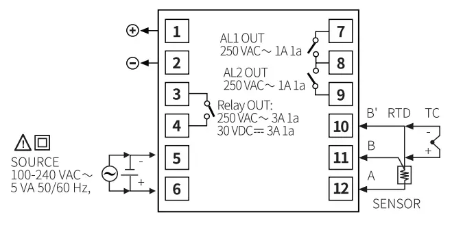
Crimp Terminal Specifications
Unit: mm, use the crimp terminal of the following shape.
Mode Setting
Parameter Reset
- Press the [◄] + [▲] + [▼] keys for over 5 sec. in run mode, INIT turns ON.
- Change the setting value as YES by pressing the [▲], [▼] keys.
- Press the [MODE] key to reset all parameter values as default and to return to run mode.
Parameter Setting
- Some parameters are activated/deactivated depending on the model or setting of other parameters. Refer to the description of each item.
- The setting range in parentheses is for using the decimal point display in the input specification.
- If there is no key input for more than 30 seconds in each parameter, it returns to RUN mode.
- When pressing the [MODE] key within 1 second after returning to the operation mode from the parameter group, it will enter the parameter group before returning.
- [MODE] key: Saves the current parameter setting value and moves to the next parameter.
[◄] key: Checks the fixed item / Moves the row when changing the set value
[▲], [▼] keys: Selects the parameter / Changes the set value - Recommended parameter setting sequence: Parameter 2 group → Parameter 1 group → SV setting
Disposal
This appear on any electrical and electronic equipment placed on the EU market. This symbol indicates that this device should not be disposed of as unsorted municipal waste at the end of its service life.
Owners of WEEE (Waste from Electrical and Electronic Equipment) shall dispose of it separately from unsorted municipal waste. Spent batteries and accumulators, which are not enclosed by the WEEE, as well as lamps that can be removed from the WEEE in a non-destructive manner, must be removed by end users from the WEEE in a non-destructive manner before it is handed over to a collection point.
Distributors of electrical and electronic equipment are legally obliged to provide free take-back of waste. Conrad provides the following return options free of charge (more details on our website):
- in our Conrad offices
- at the Conrad collection points
- at the collection points of public waste management authorities or the collection points set up by manufacturers or distributors within the meaning of the ElektroG
End users are responsible for deleting personal data from the WEEE to be disposed of. It should be noted that different obligations about the return or recycling of WEEE may apply in countries outside of Germany.
Parameter 1 group

Parameter 2 group


- The below parameters are initialized when the setting value is changed.
- Parameter 1 group: AL1/2 alarm temperature
- Parameter 2 group: Input correction, SV high/low limit, Alarm output hysteresis, LBA time, LBA band
- SV setting mode: SV
- If SV is lower than low limit or higher than high limit when the value is changed, SV is changed to the low/high limit value. If 2-1 Input specification is changed, the value is changed to Min./Max. value of Input specification.
- When the setting value is changed, the setting value of 2-20 Sensor error MV is initialized to 0.0 (OFF).
- When changing the value from PID to ONOF, each value of the following parameter is changed. 2-19 Digital input key: OFF, 2-20 Sensor error MV: 0.0 (when setting value is lower than 100.0)
This is a publication by Conrad Electronic SE, Klaus-Conrad-Str. 1, D-92240 Hirschau (www.conrad.com). All rights including translation reserved. Reproduction by any method, e.g. photocopy, microfilming, or the capture in electronic data processing systems requires prior written approval by the editor. Reprinting, also in part, is prohibited. This publication represents the technical status at the time of printing. Copyright 2024 by Conrad Electronic SE. *BN3016146 TCN_EN_TCD210225AB_20240417_INST_W
Documents / Resources
 | TRU COMPONENTS TCN4S-24R Dual Display PID Temperature Controllers [pdf] Instruction Manual TCN4S-24R Dual Display PID Temperature Controllers, TCN4S-24R, Dual Display PID Temperature Controllers, Display PID Temperature Controllers, PID Temperature Controllers, Temperature Controllers, Controllers |


