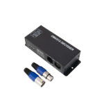
![]() DMX3-4CH-4A 4-Channel DMX512 Decoder
DMX3-4CH-4A 4-Channel DMX512 Decoder
User Manual
DMX3-4CH-4A 4-Channel DMX512 Decoder
Important: Read all instructions prior to installation.
4-Channel DMX512 Decoder
Safety and Notes
- Product should be installed in accordance with applicable national, state, and local building and electrical codes.
- To reduce the risk of electric shock, ensure that the main power source and circuit breakers are switched off before performing any installation or wiring procedures.
- Ensure all mounts are securely attached and will support the weight of the decoder. Failure to properly secure it may result in damage or injury, for which the manufacturer does not assume responsibility.
- A DMX console is required for proper use of this decoder.
Specifications
| Technical Specifications | |
| Operating Temperature | -4°–140° F (-20°–60° C) |
| Supply Voltage | 12–24 VDC |
| Max. Output Current | up to 4 A per channel, up to 15 A total |
| PWM Output | 4 Channels |
| DMX512 standard | DMX512/1990 |
Connections and Controls
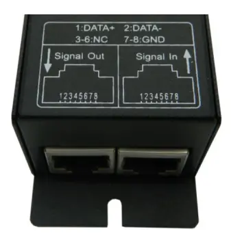 RJ45 input and output
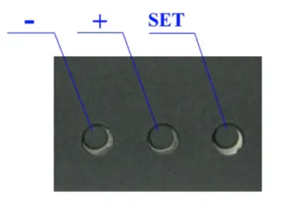 setting adjustment buttons
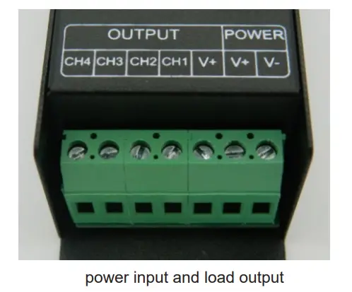
Button Function
SET button: Mode selection switch. Hold for about 2 seconds to cycle to the next mode (A/H/S). + and – buttons: These increase or decrease the DMX address value or select mode setting.
Operation
Each decoder will occupy 4 address codes. The first character on the display will be A, H, or S to display the function setting.
The remaining three characters will be the DMX address (001–512) or the mode selection. When in mode ‘A’, the decoder is being controlled by the DMX console. The digital display will show the first DMX address with the next three consecutive numbers being the remaining channels the decoder will use. So if the display shows ‘A001’, this means that the first channel is 001 and the other three channels are 002, 003, and 004 respectively. When connecting to an additional decoder, the default value of the next decoder’s first channel would be 005 and the others three channels of it would be 006, 007, and 008 in this example.
When in mode ‘H’, the decoder is using the built-in test mode programs. The remaining three character spots will display the below codes to indicate which program is currently selected.
| Display | Mode | Display | Mode |
| 0 | Turn OFF output | -5 | Static Purple |
| -1 | Static Red | -6 | Static Cyan |
| -2 | Static Green | -7 | Static White |
| -3 | Static Blue | -8 | Seven Color Jump (Speed Adjustable) |
| -4 | Static Yellow | -9 | Seven Color Fade (Speed Adjustable |
When in mode “S”, press the SET button to enter the speed adjustment setting for H-08 and H-09, then press the +/- buttons to adjust pattern speed. 
![]() Rev Date: V1 04/18/2022
Rev Date: V1 04/18/2022
4400 Earth City Expy, St. Louis, MO 63045
866-590-3533
superbrightleds.com
Documents / Resources
 | superbrightleds com DMX3-4CH-4A 4-Channel DMX512 Decoder [pdf] User Manual DMX3-4CH-4A 4-Channel DMX512 Decoder, DMX3-4CH-4A, 4-Channel DMX512 Decoder, Decoder |