
Sercel S-Lynks Gateway User Manual


Guidelines for Safe and Efficient Use
Read this information before using your S-Lynks Gateway and S-Lynks Nodes.
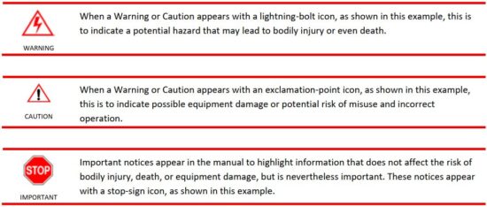
Warnings, Cautions, and Important notices throughout this manual guide you to avoid injury, prevent equipment damage, and determine equipment use when varying components or configurations exist. Notes provide tips or additional information.
SERCEL is not responsible for damages or injuries that result from failure to observe the information provided.
Description
S-lynks is a complete solution for continuous infrastructure monitoring. It analyzes the behavior of the structure and detects anomalies which makes it a great tool to meet the growing requirements for predictive maintenance programs.
This fully integrated system can be installed permanently on the structure and the data collected is immediately transmitted to a secure software platform.
The S-lynks solution is intended to conduct an audit or monitor the state of health of a structure.
The wireless acquisition and transmission of data and their frequency can be configured using a field terminal and a Powerstick or via the online service platform (for a permanent monitoring). The Nodes are powered by Sercel battery pack that can be replaced.
S-lynks Gateway

The S-lynks Gateways collect the data transmitted by the Nodes positioned on a structure.
The Gateway is installed at the location where its data collection is the most optimal in order to maximize energy performance. The data collected is sent over the field terminal (for an audit) or over the online service platform (for a permanent monitoring). The Gateway is powered by an external power supply and has an internal backup battery in case of temporary failure of the external power supply.
Functions:
- Interact with nodes (PN 10046233)
- Dual mode operation: Audit or Monitoring
- Using GNSS reception, it ensures synchronization through radio transmission to nodes.
- Transmit radio order and parameters to nodes
- Wirelessly retrieves data from Nodes (raw acquisition data, status and QC)
- Transmits processed data and raw data (if applicable) to the Cloud
- Transmits status and QC to the Cloud
- Request order from Cloud
- Allows data acquisition to be retrieved manually on a compatible terminal via Wi-Fi or Ethernet (see compatible terminal section)
- Provide batteries status with battery pack compatible (including Gauge)
External connections:
Whip Wi-Fi 2.4Ghz antenna SMA type (PN 10050547 included x1)
Whip LoRa 868Mhz antenna SMA type (PN 10050546 included x1)

External power supply Cable M12 type (PN 10050546 included x1)
External Antenna Kit (PN 10051757 not included x1)
- GPS N type with up to 50m cable & surge protection
- LTE- M N type with up to 50m cable & surge protection
Temperature sensor M12 type (included x1)
Factory Ethernet cable M12 type (not included x1)

S-lynks-Nodes
The S-lynks Nodes contain the QuietSeis® technology in order to acquire accelerometry data once positioned on a structure. The Nodes are installed directly on the structure to be monitored. The X, Y and Z axes are visible on the front face of the case in order to represent the orientation of a Node in space. The wireless acquisition and transmission of data and their frequency can be configured using a field terminal and a Powerstick (for an audit) or via the online service platform (for a permanent monitoring). The Nodes are powered by a battery pack that can be replaced.

Functions:
- Interact with Gateway (PN 10046316)
- Dual mode operation: Audit or Monitoring
- Acquisition of 3-component ambient vibration time data (raw data).
Sampling
rate: 4ms
Duration:
20mn (Monitoring mode) or selectable up to 1hour (Audit) - Wirelessly transmit data (raw acquisition data, status and QC) to Gateway
- Allows manually data to be retrieved wirelessly on compatible terminal
- Provides batteries status with battery pack compatible (including Gauge)
Description of radio protocol


Region selection: user selectable based on location
Performances:
- Max direct connections: 9 (ex: 8 nodes + 1 Tablet PC, or 9 nodes)
- Open field max distance to node: 70m


Deployment

The battery pack ref. 10052335 is not rechargeable. Do not under any circumstances attempt to recharge them (risk of injury).
Connect the internal batteries of the Nodes
To connect the internal batteries of the Nodes, follow the following procedure:
- Unscrew* the screws in the four corners of the front face of the case of the Node
- Open the cover of the case of the Node
- Remove the retainer flange from the battery pack
- Position the battery pack in the provided location, with the label visible in the cables oriented towards the bottom of the case
- Tighten* the nut of the retainer flange of the battery pack (tightening torque 7Nm in order to prevent any loosening over time)
- Connect the battery pack to the electric board of the cover
- Check that the diode of the Node has turned on when connected
- Close the cover of the case of the Node
- Progressively re-tighten* the screws in staggered fashion at the four corners of the front face of the case of the Node (tightening torque 3Nm in order to prevent any loosening over time)
*you will need a Phillips screwdriver (Pozidriv PZ2) and an M6 socket wrench (10mm).

Connect the internal batteries of the Gateways
To connect the internal batteries of the Gateways, follow the following procedure:
- Unscrew* the screws in the four corners of the front face of the case of the Gateway
- Open the cover of the case of the Gateway
- Remove the retainer flange from the battery pack
- Connect the battery pack of the Gateway (black terminal)
- Check that the diode of the Gateway has turned on when connected
- Place provided location, with the etiquette facing upwards, cable between the electronic
- board of the cover and the battery pack
- Remount and re-tighten* the retainer flange of the battery pack (tightening torque 2Nm in order
- to prevent any loosening over time)
- Close the cover of the case of the Gateway
- Progressively re-tighten* the screws in staggered fashion at the four corners of the front face of
- the case of the Gateway (tightening torque 3Nm in order to prevent any loosening over time)
*you will need a flathead screwdriver, a 3 Allen wrench (3mm) and an M6 socket wrench (10mm).

Connect the external LoRa and Wi-Fi antennas to the Gateway (optional)
This operation is carried out if you have an external LoRa or Wi-Fi whip antenna and you want to use it.

To connect the Wi-Fi and LoRa antennas with the Gateway, follow the procedure here in below:
- Have your antennas and your Gateway available
- Snap fit the antennas on the corresponding receivers:
ANT W: Wi-Fi antenna
ANT L: LoRa antenna

3. Orient the antennas in the desired direction.
4. Enable or Disable the use of the external antennas by initiating the following commands from the Acquisition menu on the application Field terminal:
a. Enable/Disable « WIFI External Antenna » for Wi-Fi.
b. Enable/Disable « LORA External Antenna » For LoRa.
Connect the external GNSS and LTE to the Gateway (optionnal)
This operation is carried out if you have an external antenna kit and you want to use it.
To connect the GNSS and LTE antennas with the Gateway, follow the procedure here in below:
- Turn OFF the Gateway and connect your antennas to the corresponding connectors

2. Connect the antennas to their cable.
5. Power on the Gateway and Enable or Disable the use of the external antennas by initiating the following commands from the Acquisition menu on the application Field terminal:
a. Enable/Disable « GNSS External Antenna » for GPS/Glonass.
b. Enable/Disable « LTE External Antenna » for LTE-M.
Position the Gateway
In order to reduce the risks of poor transmission between the Gateway and the Nodes, the latter must be positioned at the most equidistant location from all of the Nodes positioned on the structure.
- Check the green blinking signal indicating that the Gateway is turned on. If this is not the case, turn on your
Gateway by placing a Powerstick on the turn on symbol located on the front face of the case. - Position your Gateway on the structure in a stable position. The front face of the case of the Gateway (the one with the serial number of the Gateway) must imperatively be turned towards the sky for good GNSS coverage.
Support plate PN 10051066 included:

![]() In the absence of GNSS coverage, data acquisition cannot be carried out.
In the absence of GNSS coverage, data acquisition cannot be carried out.
Position the Nodes
Before positioning the Nodes, check that the latter are still turned on by checking for the presence of the green blinking signal at the base of the case. If the signal is inactive, turn on your Node by placing a Powerstick on the return on symbol located on the front face of the case or send a Lora wakeup via the Gateway with the field terminal application.
The nodes can be positioned anywhere on the structure, in a stable position. In order to carry out a valid data acquisition, the axes of the cases of the Nodes must be configured according to a common reference (reference example: River or other landscape element, road, building, etc.). This common reference will make it possible to define on which axis of the case the data acquisition will be carried out (X, Y, Z, -X, -Y or -Z) and to enter it via the application of the fuel terminal.
With support bar PN 10046676 included (x2):

Powering up the Nodes and Gateways

Boot up time (On power on or Magnetic power stick):
Audit Mode: 3 minutes
Monitoring Mode: 5 minutes
A blinking signal indicates the state of the Gateway:

Maintenance
![]() To clean the metallic enclosure of the S-lynks, use only a dry cloth.
To clean the metallic enclosure of the S-lynks, use only a dry cloth.
![]() Electrostatic discharge:
Electrostatic discharge:
Use the following guidelines to provide a static-free repair station that will preclude any ESD-related damage to electronic circuits:
- All spare parts (circuit boards and ESD sensitive devices) should be stored and transported in static- shielding bags.
- Unless the repair station rests on a conductive floor, chairs or stools should rest on a grounded, rigid-type, staticdissipative floor mat.
- Use a static-dissipative table mat.
- Wear a static-control wrist strap or foot grounder.
- Provide common-point grounding for all conductive items (including personnel and soldering iron tip).
- To control the discharge rate and protect workers from electric shocks, both the table mat and wrist strap should be grounded through a 1-MΩ resistor. The mat should be connected to the same earth ground point as the wrist strap.
- Wear static-dissipative garments.
Replace a battery pack for Gateway
To connect the internal batteries of the Gateways, follow the following procedure:
- Unscrew* the screws in the four corners of the front face of the case of the Gateway
- Open the cover of the case of the Gateway
- Remove the retainer flange from the battery pack
- Detach the battery pack from the Gateway
- Remove the battery pack from the provided location
* To carry out this operation, you will need a flathead screwdriver, a 3 Allen wrench (3mm) and and M6 socket wrench (10mm).

To connect a new battery pack, repeat the operation in the reverse order or consult “Connect the internal batteries of the Gateways”.
Tightening torque for the screws of the retainer flange of the battery pack: 2Nm

Replace a battery pack for Node
To disconnect the internal batteries from the Nodes, follow the following procedure:
- Unscrew* the screws in the four corners of the front face of the case of the Node
- Open the cover of the case of the Node
- Unscrew the nut from the retainer flange of the battery pack
- Detach the battery pack from the Node
- Remove the battery pack
* To carry out this operation, you will need a Phillips screwdriver (Pozidriv PZ2) and and M6 socket wrench (10mm).

To connect a new battery pack, repeat the operation in the reverse order or consult “Connect the internal batteries of the Nodes“.
Tightening torque for the nut of the retainer flange of the battery pack: 7Nm
Specifications


Regulatory Information
European Union Statement
Sercel products meet the essential requirements of Directives
- RED 2014/53/UE (Radio)
- 2014/ 30/UE (EMC)
- 2014/35/UE (Low Voltage)
- 2011/65/UE (ROHS).
 The S-Lynks Gateway and S-Lynks Nodes is a class-A device. In residential areas, the user may be requested to take appropriate measures in the event of RF interference caused by this device.
FCC US Statement
Changes or modifications not expressly approved by the party responsible for compliance could void the user’s authority to operate the equipment.
This device complies with part 15 of the FCC Rules. Operation is subject to the following two conditions:
(1) This device may not cause harmful interference, and
(2) this device must accept any interference received, including interference that may cause undesired operation
Note: This equipment has been tested and found to comply with the limits for a Class A digital device, pursuant to part 15 of the FCC Rules. These limits are designed to provide reasonable protection against harmful interference when the equipment is operated in a commercial environment. This equipment generates, uses, and can radiate radio frequency energy and, if not installed and used in accordance with the instruction manual, may cause harmful interference to radio communications. Operation of this equipment in a residential area is likely to cause harmful interference in which case the user will be required to correct the interference at his own expense.
This equipment complies with FCC’s radiation exposure limits set forth for an uncontrolled environment under the following conditions :
- This equipment should be installed and operated such that a minimum separation distance of 20cm is maintained between the radiator (antenna) and user’s/nearby person’s body at all times.
- This transmitter must not be co-located or operating in conjunction with any other antenna or transmitter.
IC Canadian Statement
SERCEL products comply with Industry Canada EMI Class A requirements according to ICES-003 and RSS Gen.
Les produits SERCEL sont conformes aux exigences Classe A de l’Industrie Canada selon les normes NMB-003 et CNR Gen.
Note These devices comply with Industry Canada’s license-exempt RSSs. Operation is subject to the following two conditions:
- These devices may not cause interference; and
- These devices must accept any interference, including interference that may cause undesired operation of the device.
This equipment complies with RSS102’s radiation exposure limits set forth for an uncontrolled environment under the following conditions:
- This equipment should be installed and operated such that a minimum separation distance of 20cm is maintained between the radiator (antenna) and user’s/nearby person’s body at all times.
- This transmitter must not be co-located or operating in conjunction with any other antenna or transmitter.
Read More About This Manual & Download PDF:
Documents / Resources
 | Sercel S-Lynks Gateway [pdf] User Manual S-Lynks Gateway, S-Lynks, Gateway |