robustel EG5200 Industrial Edge Computing Gateway Owner’s Manual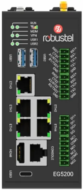
Regulatory and Type Approval Information
Table 1: Toxic or Hazardous Substances or Elements with Defined Concentration Limits
| Name of the Part | Hazardous Substances | |||||||||
| (Pb) | (Hg) | (Cd) | (Cr(VI)) | (PBB) | (PBDE) | (DEHP) | (BBP) | (DBP) | (DIBP) | |
| Metal parts | o | o | o | o | – | – | – | – | – | – |
| Circuit modules | o | o | o | o | o | o | o | o | o | o |
| Cables and cable assemblies | o | o | o | o | o | o | o | o | o | o |
| Plastic and polymeric parts | o | o | o | o | o | o | o | o | o | o |
| o: Indicates that this toxic or hazardous substance contained in all of the homogeneous materials for this part is below the limit requirement in RoHS2. 0. X: Indicates that this toxic or hazardous substance contained in at least one of the homogeneous materials for this part might exceed the limit requirement in RoHS 2. 0.-:Indicates that it does not contain the toxic or hazardous substance. | ||||||||||
Radio Specifications for Europe
| RF technologies | 2G, 3G, 4G, GNSS, Wi-Fi*, BLE* | |
| Cellular Frequency * | EU Band:4G: LTE FDD: B1/B3/B7/B8/B20/B28/B32 LTE TDD: B34/B38/B40/B42/B43/B46 3G: WCDMA: B1/B82G: GSM: B3/B8 | Non-EU Band:4G: LTE FDD: B2/B4/B5/B12/B13/B18/B19/B25/B26 LTE TDD: B39/B413G: WCDMA: B2/B4/B5/B6/B192G: GSM: B2/B5 |
| Wi-Fi Frequency | 2.4 GHz: 2.412 ~ 2.484 GHz5 GHz: 5150-5250MHz, 5745-5825MHz | |
| BLE Frequency | 2400 ~ 2483.5MHz | |
| GNSS* | GPS L1, Galileo E1, GLONASS G1, BDS B1I, SBAS L1: 1559MHz to 1610MHz BDS B2a, GPS L5,Galileo E5a: 1164MHz to 1215MHz | |
| Max RF power | 33 dBm±2dB@GSM, 24 dBm+1/-3dB@WCDMA, 23 dBm±2dB@LTE, 19dBm@WiFi, 4dBm@BLE | |
- May vary on difference models.
Note: Operation of 5150 ~ 5250 MHz frequency range is restricted to indoor use only.
 | AT | BE | BG | CH | CY | CZ | DE | DK |
| EE | EL | ES | Fl | FR | HR | HU | IE | |
| IS | IT | LI | LT | LU | LV | MT | NL | |
| NO | PL | PT | RO | SE | SI | SK | UK |
Caution: The user is cautioned that changes or modifications not expressly approved by the party responsible for
compliance could void the user’s authority to operate the equipment.
This device contains licence-exempt transmitter(s)/receiver(s) that comply with Innovation, Science and Economic
Development Canada’s licence-exempt RSS(s) and Part 15 of the FCC Rules. Operation is subject to the following two conditions:
(1) This device may not cause interference.
(2) This device must accept any interference, including interference that may cause undesired operation of the
device.
Note: This equipment has been tested and found to comply with the limits for a Class B digital device, pursuant to Part 15 of the FCC Rules. These limits are designed to provide reasonable protection against harmful interference in a residential installation. This equipment generates, uses and can radiate radio frequency energy and, if not installed and used in accordance with the instructions, may cause harmful interference to radio communications. However, there is no guarantee that interference will not occur in a particular installation.
If this equipment does cause harmful interference to radio or television reception, which can be determined by turning the equipment off and on, the user is encouraged to try to correct the interference by one or more of the following measures:
- Reorient or relocate the receiving antenna.
- Increase the separation between the equipment and receiver.
- Connect the equipment into an outlet on a circuit different from that to which the receiver is connected.
- Consult the dealer or an experienced radio/TV technician for help.
FCC& IC Radiation Exposure Statement
This equipment complies with FCC and Canada radiation exposure limits set forth for an uncontrolled environment.
This equipment should be installed and operated with a minimum distance of 20cm between the radiator and your body.
This transmitter must not be co-located or operating in conjunction with any other antenna or transmitter.
Simplified EU Declaration of Conformity
We, Guangzhou Robustel Co., Ltd. are located at 501, Building #2, 63 Yongan Road, Huangpu District, Guangzhou, China, declare that this radio equipment complies with all applicable EU directives. The full text of the EU DoC is available at the following internet address:
www.robustel.com/certifications/
Safety Information
General
- The router generates radio frequency (RF) power. When using the router, care must be taken on safety issues related to RF interference as well as regulations of RF equipment.
- Do not use your router in aircraft, hospitals, petrol stations or in places where using cellular products is prohibited.
- Be sure that the router will not be interfering with nearby equipment. For example: pacemakers or medical equipment. The antenna of the router should be away from computers, office equipment, home appliance, etc.
- An external antenna must be connected to the router for proper operation. Only uses approved antenna with the router. Please contact authorized distributor on finding an approved antenna.
RF Exposure - This device meets the official requirements for exposure to radio waves. This device is designed and manufactured not to exceed the emission limits for exposure to radio frequency (RF) energy set by authorized agencies.
- The device must be used with a minimum separation of 20 cm from a person’s body to ensure compliance with RF exposure guidelines. Failure to observe these instructions could result in your RF exposure exceeding the applicable limits.
Note: Some airlines may permit the use of cellular phones while the aircraft is on the ground and the door is open. Router may be used at this time.![]()
The symbol indicates that the product should not be mixed with general household waste but must be sent to separate collection facilities for recovery and recycling.![]()
The symbol indicates that the product meets the requirements of the applicable EU directives.![]()
The symbol indicates that the product meets the requirements of the relevant UK legislation.
Find more product documents or tools at: www.robustel.com/documentation/
Technical Support
Tel: +86-20-82321505
Email: support@robustel.com
Web: www.robustel.com
Document History
Updates between document versions are cumulative. Therefore, the latest document version contains all updates
made to previous versions.
| Date | Firmware Version | Document Version | Change Description |
| Jun. 27, 2023 | 2.1.0 | 1.0.0 | Initial release. |
Overview
EG5200 is a new generation of industrial edge computing gateway, supporting global 4G/3G/2G networks for cellular backhaul, with a fully-fledged Debian 11(bullseye) based operating system able to support thousands of existing or new ARMv8 (Raspberry Pi compatible) based applications.
Package Checklist
Before commencing installation ensure your package has the following components:
| Device | 2PIN Terminal Block with Lock | 4PIN Terminal Block | 5PIN Terminal Block | 6PIN Terminal Block |
 |  |  |  |  |
| Mounting Kit | RCMS Card | Quick Start Guide Card | Wi-Fi Antenna (Optional) | Cellular Antenna (Optional) |
 |  |  |  |  |
| Power Supply (Optional) |  | |||
Note: The accessories could be different on specific order.
Panel Layout
(May vary on different models, please refer to Table1)
- Top View

- Front View

- Bottom View

Table 1
| Model | PN | Cellular Antenna Port | WIFI/BLE Antenna Port | GNSS Antenna Port |
| EG5200-A5ZAZ-NU | B120001 | 0 | 0 | 0 |
| EG5200-A5CAZ-NU | B120002 | 0 | 2 | 0 |
| EG5200-A5AAZ-4L-A06GL_EG25-G | B120004 | 2 | 0 | 1 |
| EG5200-A5BAZ-4L-A06GL_EG25-G | B120006 | 2 | 2 | 1 |
Interface Descriptions
- Serial Ports. Two software configurable serial ports, could be configured as RS232 or RS485 or RS422.
Name RS232 Mode RS485 Mode RS422 Mode RXD1 or RX1+ data receiving data receiving positive CTS1 or RX1- clear to send data receiving negative A1/RTS1 or TX1+ request to send RS485_A1 data sending positive B1/TXD1 or TX1- data sending RS485_B1 data sending negative GND Ground Ground Ground RXD2 or RX2+ data receiving data receiving positive CTS2 or RX2- clear to send data receiving negative A2/RTS2 or TX2+ request to send RS485_A2 data sending positive B2/TXD2 or TX2- data sending RS485_B2 data sending negative GND Ground Ground Ground - Ethernet Ports. 5 Ethernet ports, both of them could be configured as WAN or LAN.
LED Description Activity On, blinking Transmitting data Off No activity Link Off Link off On Link on - Reset Button.
Function Operation Reboot Press and hold the RST button for 2~5 seconds under the operating status. Restore to default configuration Press and hold the RST button for 5 ~10 seconds under the operating status.The RUNlight flashes quickly, and then release theRST button, and the device will restore to the default configuration. Restore to factoryconfiguration Once the operation of restoring the default configuration is performed twice withinone minute, the device will restore to the factory default settings. - Digital Input and Relay Output. Two sets of digital inputs. Some applications for reference are as below:

Note: The external power supply DC voltage range is 5V~30V, 0.1A max.Name Type Description DI1+ Digital I/O Digital Input positive DI1- Digital Input negative DI2+ Digital Input positive DI2- Digital Input negative NC1 Relay Output Normally Closed COM1 Common NO1 Normally Open NC2 Normally Closed COM2 Common NO2 Normally Open - LED Indicators.
LED Description RUN On, solid Gateway system is initializing On, blinking Gateway starts operating Off Gateway is powered off MDM Color With 4G Module:2G: Red, 3G: Yellow, 4G: Green On, blinking Link connection is working Off Link connection is not working 
Green Strong signal Yellow Medium signal Red Weak or no signal VPN On, solid VPN connection is established Off VPN connection is not established USR1/USR2 Defined by user
Hardware Installation
- SIM Card Installation. Remove the SIM card cover to insert the SIM cards into the device, then screw up the cover.

- Antenna Installation. Rotate the antenna into the antenna connector accordingly.

Rubber Antenna Installation - Terminal Block Installation. Insert the 4 PIN,5PIN and 6PIN terminal blocks into the interfaces connector, then can connect the devices or sensors to the gateway with wires via corresponding interfaces.’

- Power Supply installation. Insert the power supply cord into the corresponding terminal block if needed, then insert the terminal block into the power connector.

- DIN Rail Mounting. Use 2 M3 screws to fix the DIN rail to the device, then hang the DIN rail on the mounting bracket.

- Wall Mounting. Use 4 M3 screws to fix the DIN rail to the device, then hang the DIN rail on the mounting bracket.

- Grounding the Device. Grounding will help to prevent the noise effect due to electromagnetic interference (EMI). Connect the device to the site ground wire by the grounding screw before powering on.
Login to the Device
- Connect the gateway’s Ethernet port to a PC with a standard Ethernet cable.
- Before logging in, manually configure the PC with a static IP address on the same subnet as the gateway address, click and configure “Use the following IP address”

- To enter the gateway’s web interface, type http://192.168.0.1 into the URL field of your
Internet browser. - Use login information shown in the product label when prompted for authentication.

- After logging in, the home page of the web interface is displayed, then you can view system information and perform configuration on the device.

- The automatic APN selection is ON by default, if need to specify your own APN, please go to the menu Interface->Cellular->Advanced Cellular Setting->General Settings to finish the specific setting.

- For more configuration details please refer to RT104_SM_RobustOS Pro Software Manual. (END)

Support: support@robustel.com
Website: www.robustel.com
©2023 Guangzhou Robustel Co.,Ltd.
All rights reserved. Subject to change without notice.
Documents / Resources
 | robustel EG5200 Industrial Edge Computing Gateway [pdf] Owner's Manual EG5200, EG5200 Industrial Edge Computing Gateway, Industrial Edge Computing Gateway, Edge Computing Gateway, Computing Gateway, Gateway |


