Raychem NGC-40-HTC Control and Monitoring Modules
Product Information
- The NGC-40-HTC & NGC-40-HTC3 are Control and Monitoring Modules designed for use with the Raychem NGC-40 System.
- These modules are approved and certified for Hazardous Locations according to various standards and certifications, including FM STD 3600 & 3611, UL STD 121201, CSA STD C22.2# 213, IEC Ex Markings, and ATEX Markings.
- The modules come in two variants: NGC-40-HTC for single-phase heaters and NGC-40-HTC3 for three-phase heaters.
- They are electrical devices that must be installed correctly to ensure proper operation and safety.
Product Usage Instructions
- This component is an electrical device that must be installed correctly to ensure proper operation and to prevent shock or fire.
- For technical support, call Chemelex at 800-545-6258.
Control and Monitoring Modules for use with Raychem NGC-40 System Installation Instructions
APPROVALS AND CERTIFICATIONS
Hazardous Locations
| Hazardous Locations | |
| Class I, Div. 2, Groups A, B, C, D T4 Class I, Zone 2, AEx ec nC IIC T4 Gc IP20 Ex ec nC IIC T4 Gc X
| |
| Conforms to: FM STD 3600 & 3611, UL STD 121201, 60079-0, 60079-7, 60079-15, 61010-1, 61010-2-201 | |
| Certified to: CSA STD C22.2# 213, 60079-0, 60079-7, 60079-15, 61010-1, 61010-2-201 | |
| IEC Ex Markings: IEC Ex ETL17.0062X Ex ec nC IIC T4 Gc | ATEX Markings: ITS17ATEX402833X
|
 –40°C ≤ Ta ≤ +65°C
DESCRIPTION
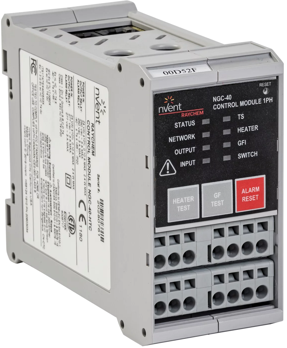
- The Raychem NGC-40-HTC (for single-phase heaters) and NGC-40-HTC3 (for three-phase heaters) modules are used to control either an external solid-state relay or a contactor within the NGC‑40 control and monitoring system.
- These modules also have one alarm output and one digital input.
- The alarm output can be used to activate an external annunciator.
- The digital input is programmable and may be used for various functions, such as forcing outputs on and off.
- Other features include ground-fault and line current sensing for both HTC and HTC3.
- The front panel of the HTC modules has LED indicators for various status conditions.
- The front panel also provides a ground-fault and heater test button.
TOOLS REQUIRED
- Small flat-blade screwdriver
ADDITIONAL MATERIALS
- Power supply 24 Vdc @100 mA per NGC-40-HTC/HTC3
- Custom-built CAN cables with RJ-45 connections
- CAN Termination Resistor
- Custom-built CAN cables with RJ-45 connections
- CAN Termination Resistor
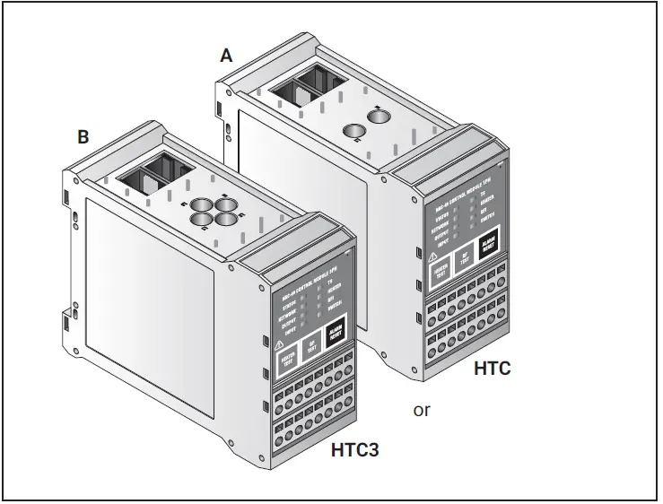
KIT CONTENTS
| Item | Qty | Description |
| A | 1 | NGC-40-HTC module (single-phase heaters) |
| or | ||
| B | 1 | NGC-40-HTC3 module (three-phase heaters) |
Special conditions of use
- The overall equipment is evaluated to type of protection “ec”. Sealed devices in the form of relays are additionally present in module NGC-40-HTC and NGC-40-HTC3 and comply with requirements for the type of protection nC.
- For full connection details, see these installation instructions.
- The equipment shall only be used in an area of not more than pollution degree 2, as defined in IEC/EN 60664-1.
- The equipment shall be installed in an enclosure that provides a minimum ingress protection of IP54 in accordance with IEC/EN 60079-0.
- Transient protection shall be provided that is set at a level not exceeding 140% of the peak rated voltage value at the supply terminals to the equipment.
WARNING
- This component is an electrical device that must be installed correctly to ensure proper operation and to prevent shock or fire.
- For technical support, call Chemelex at 800-545-6258.
Specifications
GENERAL
| Supply voltage | 24 Vdc ± 10% |
| Internal power consumption | <2.4 W per NGC-40-HTC/HTC3 module |
| Ambient operating temperature | –40°C to 65°C (–40°F to 149°F) |
| Ambient storage temperature | –55°C to 75°C (–67°F to 167°F) |
| Environment | PD2, CAT III |
| Max. altitude | 2,000 m (6,562 ft) |
| Humidity | 5 – 90% noncondensing |
| Mounting | Din Rail – 35 mm |
ELECTROMAGNETIC COMPATIBILITY
| Emissions | EN 61000-6-3 Emission standard for residential, commercial and light industrial environments |
| Immunity | EN 61000-6-2 Immunity standard for industrial environments |
TEMPERATURE SENSORS
| Type | 100 Ω platinum RTD, 3-wire, α = 0.00385 ohms/ohm/°C Can be extended with a 3-conductor shielded cable of 20 Ω maximum per conductor 100 Ω, Ni-Fe, 2-wire Can be extended with a 2-wire shielded cable of 20 Ω maximum per conductor |
| Quantity | One per NGC-40-HTC/HTC3 module |
ALARM RELAY
| Dry contact relay (voltage free) | Relay contact rated 250 V / 3 A 50/60 Hz (EC) and 277 V / 3 A 50/60 Hz (cCSAus). Alarm relay is programmable. NO and NC contacts available. |
CONTACTOR OUTPUT RELAY
- Relay contact rated 250 V / 3 A
- 50/60 Hz (CE) and 277 V / 3 A
- 50/60 Hz (c-CSA-us).
| DIGITAL INPUT | |
| Multi-purpose input | Multi-purpose input for connection to external dry (voltage-free) contact or DC voltage. May be user programmable for: not used / force off/force on functions. It can be configured to be active, open or active closed. |
CAN NETWORKING PORT
| Type | 2-wire isolated CAN-based peer-to-peer network. Isolated to 24 Vdc – verified by 500 Vrms dielectric withstand test |
| Connection | Two 8-pin RJ-45 connectors (both may be used for Input or Output connections) |
| Protocol | Proprietary NGC-40 |
| Topology | Daisy chain |
| Cable length | 10 m (33 ft) maximum |
| Quantity | Up to 80 HTC/HTC3 and IO modules per network segment |
| Address | Unique, factory-assigned |
CONNECTION TERMINALS
| Wiring terminals | Cage clamp, 0.5 to 2.5 mm2 (24 to 12 AWG) |
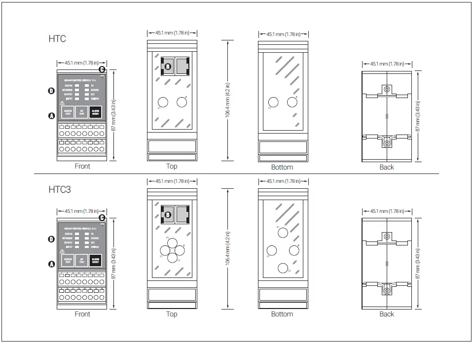
HOUSING
| Size | 45.1 mm (1.78 in) wide x 87 mm (3.43 in) high x 106.4 mm (4.2 in) deep |
LINE CURRENT SENSORS
| Max current | 63 A |
| Accuracy | ± 2% of reading |
GROUND-FAULT SENSOR
| Range | 10 – 250 mA |
| Accuracy | ± 2% of range |
OUTPUTS
| SSR output | 12 Vdc @ 45 mA max per output |
System Components
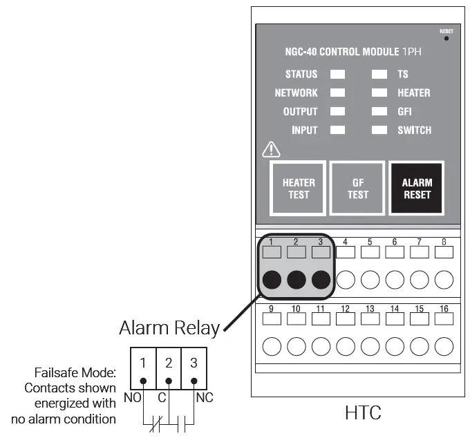
A. Wiring terminals
| Terminals | Function |
| 1 | Alarm relay N.O. |
| 2 | Alarm relay COM |
| 3 | Alarm relay N.C. |
| 4 | Not used |
| 5 | SSR Out + |
| 6 | SSR Out – |
| 7 | Digital In + |
| 8 | Digital In – |
| 9 | Line In |
| 10 | Line Out |
| 11 | Coil Out |
| 12 | |
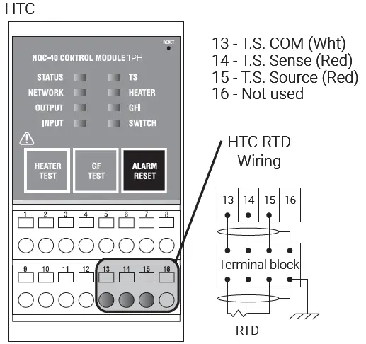
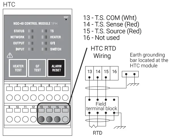
| 13 | TS COM (Wht) |
| 14 | TS Sense (Red) |
| 15 | TS Source (Red) |
| 16 | Not used |
WARNING: Shock Hazard. Disconnect from live voltage prior to accessing terminals
- B. CAN bus/Module power
- C. RESET
- D. STATUS LEDS
| D. STATUS LEDS Heater: Indicates the heater’s alarm status | ||||
| Status: Indicates the status of the HTC/HTC3 module | Off | No alarm | ||
| High or low current or resistance alarm | ||||
| Off | No power | Red | ||
| Green | Normal operation, no internal faults | Flash R | Overcurrent trip alarm | |
| Yellow | In Factory mode | TS: Indicates the temperature alarm status | ||
| Red | HTC/HTC3 operating status | Off | No alarm | |
| Flash R | Internal Fault: | Red | High or low temperature alarm | |
| Flash R/G | Factory status | Flash R | Temperature sensor failure | |
| Flash R/Y | Internal fault detected | GFI: Indicates ground-fault status | ||
| Network: Indicates CAN network activity | Off | No alarm | ||
| Off | No network activity | Red | High or low ground-fault alarm | |
| Green | Flicker on receipt of network data | Flash R | Ground-fault trip alarm | |
| Yellow | Flicker on the transmission of network data | Switch: Indicates contactor/ SSR switch status | ||
| Flash R | Network communication failure | Off | No alarm | |
| Red | Contractor cycle count alarm | |||
| Input: Shows the status of the digital input | Flash R | Switch failed shorted on | ||
| Off | Input is inactive (open) | |||
| Green | Input is active (shorted) | |||
| Flash R | Ext. input source failure | |||
| Output: Shows the status of the contactor or SSR | ||||
| Off | Output off | |||
| Green | Follows the output state | |||
Mounting the NGC-40-HTC/HTC3
- Each NGC-40-HTC/HTC3 mounts on a DIN 35 rail.
- MOUNTING: Insert the rear bottom of the module into the DIN rail, then push up and inwards to engage the clip.

REMOVAL: Push the module upwards to disengage the clip, then rotate the module toward you.

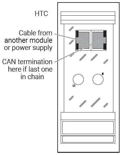
Power Supply/CAN
- The power supply/CAN connector is an RJ-45 connector.
- The CAN termination device must be installed in the unused port of the last module.
- Connections are the same for the HTC3.
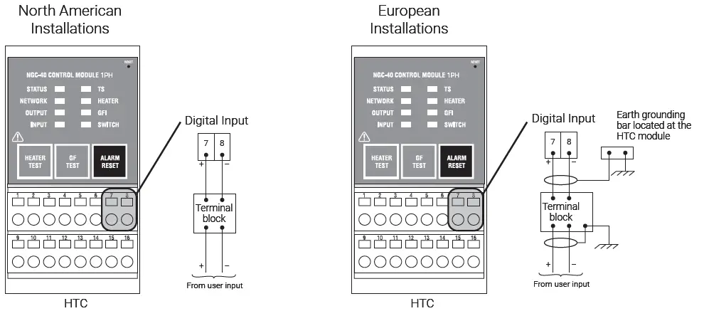
RTD Input Connections – North American Installation Technique
- For all RTD terminations, the RTD field wires must be terminated on a panel-mounted terminal block.
- Connections are the same for the HTC3.
RTD Input Connections – European Installation Technique
- For all RTD terminations, the RTD field wires must be terminated on a panel-mounted terminal block.
- The RTD cable shield from the field terminal block to the HTC module should be terminated at the earth ground bar located near the module.
- Connections are the same for the HTC3.
Power Supply/CAN
- Terminals 9 and 11 switch voltage to the contactor coils. The internal pilot relay will switch the supply voltage (up to 277 V) to the contactor coil. Refer to the diagram at the end of this document called “NGC-40 CAN bus Connections for Up to 10 Modules” for detail wiring.
- Note: Exposure to some chemicals may degrade the sealing properties of the relay output, manufactured by NAIS, PN JQ1P-12V. Periodically inspect the relay output for degradation of properties and replace if any degradation is found.
- Connections are the same for the HTC3.

WARNING: Shock Hazard. Disconnect from live voltage prior to accessing terminals.
HTC3 Relay Output to Contactor – Three-Phase

WARNING: Shock Hazard. Disconnect from live voltage prior to accessing terminals.
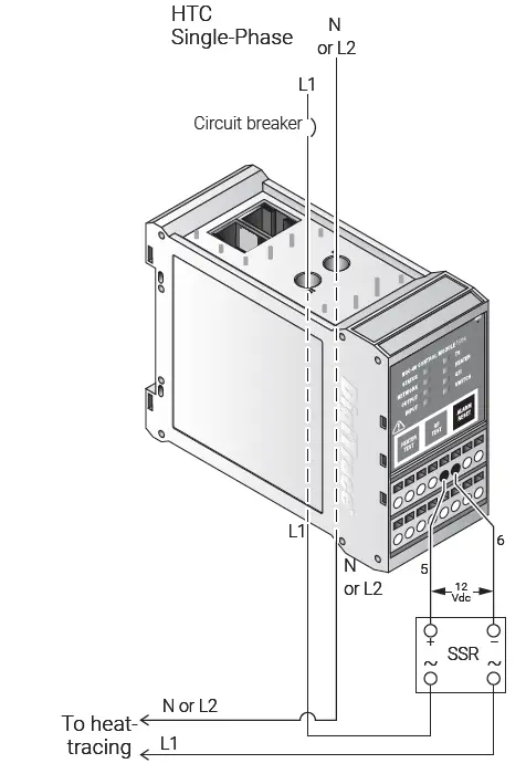
HTC Output Connections to SSR – Single-Phase
- Terminals 5 & 6 switch voltage to the SSR. The internal SSR driver will switch the internal supply voltage (12 Vdc) to the SSR.
HTC3 Output Connections to SSR – Three-Phase

WARNING: Shock Hazard. Disconnect from live voltage prior to accessing terminals.
Alarm
- WARNING: Shock Hazard. Disconnect from live voltage prior to accessing terminals.
- Note: Exposure to some chemicals may degrade the sealing properties of the alarm relay, manufactured by NAIS, PN JQ1P-12V. Periodically inspect the alarm relay for degradation of properties and replace if any degradation is found.
- Multi-purpose. Alarm relay is energized in the normal state.
- The alarm relay is configured as Fail Safe.
- The alarm relay connections provide a form C dry contact, rated at 277 V max (3 A).
- The NO (normally open) contact is open in a non-energized condition. When energized, it closes during normal conditions and will open upon an alarm condition or power failure.
- The NC (normally closed) contact is closed in a non-energized condition. When energized, it opens during normal conditions and will close upon an alarm condition or power failure.
- Relay contact rated
- 250 V / 3A 50/60 Hz (CE)
- 277 V / 3A 50/60 Hz (c-CSA-us)
- Connections are the same for the HTC3.
Digital Input Connections – North American and European Installation Techniques
- Digital Input: Multi-purpose input for connection to external dry (voltage-free) contact or DC voltage.
- Rating 100 Ω max loop resistance or 5-24 Vdc @ 1 mA maximum
- Connections are the same for the HTC3.
Provide Suitable Panel Enclosure and Determine Locations for the NGC-40-HTC or NGC-40-HTC3 Assembly in Panel*
- Provide a suitable panel enclosure
The NGC-40-HTC or NGC-40-HTC3 must be mounted in an enclosure to protect its electronic components. For indoor applications, use a minimum NEMA 1 enclosure (NEMA 12 recommended). For outdoor applications, use a NEMA 4 or NEMA 4X enclosure depending on the requirements.
Note: The Raychem NGC-40-HTC or NGC-40-HTC3 is designed for operation in ambient temperatures from –40°C to 65°C (–40°F to 149°F). If the ambient temperature is outside this range, a space heater and/or cooling fan will be required in the panel. - Determine locations for the NGC-40-HTC or NGC-40-HTC3 assembly in the electrical panel.
The NGC-40-HTC or NGC-40-HTC3 should be located in the rear of the panel. The NGC-40-HTC or NGC-40-HTC3 assembly is an electronic unit and must not be located where it will be exposed to strong magnetic fields or excessive vibration.
North American panel installation techniques

NGC-40 CAN Bus Connections for Up to 10 Modules
- Power supply shall have a means for disconnect from line voltage
NGC-40 CAN Bus Connections for Up to 20 Modules

- Power supply shall have a means for disconnect from line voltage
NGC-40 CAN Bus Connections for Up to 40 Modules

- Power supply shall have a means for disconnecting from the line voltage
Servicing
The NGC-40-HTC/HTC3 contains no user serviceable parts. Contact your Chemelex representative for service and an RMA number if required.
- WARNING: Explosion Hazard – Substitution of components may impair suitability for Class I, Division 2 hazardous and nonhazardous locations
- WARNING: Explosion Hazard – Do not replace NGC-40-PTM unless power has been switched off or the area is known to be nonhazardous
- WARNING: Explosion Hazard – Do not disconnect equipment unless power has been switched off or the area is known to be nonhazardous
©2025 Chemelex. All Chemelex marks and logos are owned or licensed by Chemelex Europe GmbH or its affiliates. All other trademarks are the property of their respective owners. Chemelex reserves the right to change specifications without notice.
RAYCHEM-IM-H58087-NGC40HTC-EN-2504
CONTACT
North America
- Tel +1 800 545 6258
- info@chemelex.com
Latin America
- Tel +1 713 868 4800
- info@chemelex.com
Europe, Middle East, Africa, India
- Tel +32 16 213 511
- Fax +32 16 213 604
- info@chemelex.com
Asia Pacific
- Tel +86 21 2412 1688
- infoAPAC@chemelex.com
FAQ
Q: What should I do if I encounter installation issues?
A: If you encounter any installation issues, please contact Chemelex technical support at 800 545-6258 for assistance.
Q: Can the NGC-40-HTC module be used with both single-phase and three-phase heaters?
A: No, the NGC-40-HTC module is designed specifically for single-phase heaters. For three-phase heaters, use the NGC-40-HTC3 module.
Documents / Resources
 | Raychem NGC-40-HTC Control and Monitoring Modules [pdf] Installation Guide NGC-40-HTC, NGC-40-HTC3, NGC-40-HTC Control and Monitoring Modules, NGC-40-HTC, Control and Monitoring Modules, Monitoring Modules, Modules |