![]()
DIGITAL I/O MODULE
OB-215
OPERATING MANUAL
Quality Management System of the device designing and production complies with the requirements of ISO 9001:2015
Dear Customer,
Novatek-Electro Ltd. company thanks you for purchasing our products. You will be able to use properly the device after carefully studying the Operating Manual. Keep the Operating Manual throughout the service life of the device.
DESIGNATION
Digital I/O module OB-215 hereinafter referred to as the “device” can be used as the following:
– remote DC voltage meter (0-10V);
– remote DC meter (0-20 mA);
– remote temperature meter with the ability to connect sensors -NTC (10 KB),
PTC 1000, PT 1000 or digital temperature sensor DS/DHT/BMP; temperature regulator for cooling and heating plants; pulse counter with saving the result in memory; pulse relay with switching current up to 8 A; interface converter for RS-485-UART (TTL).
OB-215 provides:
equipment control using relay output with switching capacity up to 1.84 kVA; tracking the state (closed/open) of the contact at the dry contact input.
RS-485 interface provides control of the connected devices and reading of the sensors readings via the ModBus protocol.
Parameter setting is set by the user from the Control Panel using the ModBus RTU/ASCII protocol or any other program that allows working with the ModBus RTU / ASCII protocol.
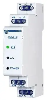
The status of the relay output, the presence of the power supply and the data exchange are displayed using indicators located on the front panel (Fig. 1, it. 1, 2, 3).
The overall dimensions and layout of the device are shown in Fig. 1.
Note: Temperature sensors are included in the delivery scope as agreed upon.

- indicator of data exchange via RS-485 interface (it is on when data is being exchanged);
- indicator of the status of the relay output (it is on with closed relay contacts);
- indicator
 is on when there is supply voltage;
 - terminals for connecting RS-485 communication;
- device power supply terminals;
- terminal for reloading (resetting) the device;
- terminals for connecting sensors;
- output terminals of relay contacts (8A).
OPERATION CONDITIONS
The device is intended for operation in the following conditions:
– ambient temperature: from minus 35 to +45 °C;
– atmospheric pressure: from 84 to 106.7 kPa;
– relative humidity (at temperature of +25 °C): 30 … 80%.
If the temperature of the device after transportation or storage differs from the ambient temperature at which it is supposed to be operated, then before connecting to the mains keep the device under the operating conditions within two hours (because of condensation may be on the device elements).
The device is not intended for operation in the following conditions:
– significant vibration and shocks;
– high humidity;
– aggressive environment with content in the air of acids, alkalis, etc., as well as severe contaminations (grease, oil, dust, etc.).
SERVICE LIFE AND WARRANTY
The lifetime of the device is 10 years.
Shelf life is 3 years.
Warranty period of the device operation is 5 years from the date of sale.
During the warranty period of operation, the manufacturer performs free repair of the device, if the user has complied with the requirements of the Operating Manual.
Attantion! The User loses the right for warranty service if the device is used with violation of the requirements of this Operating Manual.
Warranty service is performed at the place of purchase or by the manufacturer of the device. Post-warranty service of the device is performed by the manufacturer at current rates.
Before sending for repair, the device should be packed in the original or other packing excluding mechanical damage.
You are kindly requested, in case of the device return and transfer it to the warranty (post-warranty) service please indicate detailed reason for the return in the field of the claims data.
ACCEPTANCE CERTIFICATE
OB-215 is checked for operability and accepted in accordance with the requirements of the current technical documentation, is classified as fit for operation.
Head of QCD
Date of manufacture
Seal
TECHNICAL SPECIFICATIONS
Table 1 – Basic Technical Specincations
| Rated power supplyvoltage | 12 – 24 V |
| ‘The error error of measuring DC voltage in the range of 0-10 AV, min | 104 |
| The error of measuring DC in the range of 0-20 mA, min | 1% |
| !Temperature measurement range (NTC 10 KB) | -25…+125 °C |
| “Temperature measurement error (NTC 10 KB) from -25 to +70 | ±-1 °C |
| Temperature measurement error (NTC 10 KB) from +70 to +125 | ±2 °C |
| Temperature measurement range (PTC 1000) | -50…+120 °C |
| Temperature measurement error (PTC 1000) | ±1 °C |
| Temperature measurement range (PT 1000) | -50…+250 °C |
| Temperature measurement error(PT 1000) | ±1 °C |
| Max. pulses frequency in “Pulse Counter/Logic Input* .mode | 200 Hz |
| Max. voltage given on an «101» input | 12 V |
| Max. voltage given on an «102» input | 5 V |
| Readiness time, max | 2 s |
| ‘Max. switched current with active load | 8 A |
| Quantity and type of relay contact (switching contact) | 1 |
| Communication Interface | RS (EIA/TIA)-485 |
| ModBus data exchange protocol | RTU / ASCII |
| Rated operating condition | continuous |
| Climatic design version Protection rating of the device | NF 3.1 P20 |
| Thermissible contamination level | II |
| Naximal power consumption | 1 W |
| Electric shock protection class | III |
| !Wire cross-section forconnection | 0.5 – 1.0 me |
| Tightening torque of screws | 0.4 N*m |
| Weight | s 0.07 kg |
| Overall dimensions | •90x18x64 mm |
‘The device meets the requirements of the following: EN 60947-1; EN 60947-6-2; EN 55011: EN 61000-4-2
Installation is on standard 35 mm DIN-rail
Position in space – arbitrary
Housing material is self-extinguishing plastic ‘
Harmful substances in amounts exceeding maximum permissible concentrations are not available
| Description | Range | Factory setting | Type | W/R | Address (DEC) |
| Digital signals measurement: 0 – pulse counter; 1 – logic input/pulse relay. Analog signals measurement: 2 – voltage measurement; 3 – current measurement. Temperature measurement: 4 – NTC (10KB) sensor; 5- PTC1000sensor; 6 – PT 1000 sensor. Interface transformation mode: 7 – RS-485 – UART (TTL); 8 _d igita I sensor ( 1-Wi re, _12C)* | 0 … 8 | 1 | UINT | W/R | 100 |
| Connected digital sensor | |||||
| O – 0518820 (1-Wire); 1- DHT11 (1-Wire); 2-DHT21/AM2301(1-Wire); 3- DHT22 (1-Wire); 4-BMP180(12C) | 0 .. .4 | 0 | UINT | W/R | 101 |
| Temperature correction | -99…99 | 0 | UINT | W/R | 102 |
| Relay control: 0 – control is disabled; 1 – relay contacts are opened at a value above the upper threshold. they are closed at a value below thei lower threshold; 2 – relay contacts are closed at a value above the upper threshold, they are opened at a value below the lower threshold; 3 – relay contacts are opened at a value above the upper threshold or below the lower threshold and are: closed at a value below the upper threshold and above the lower: | 0 … 3 | 0 | UINT | W/R | 103 |
| Upper threshold | -500…2500 | 250 | UINT | W/R | 104 |
| Lower threshold | -500…2500 | 0 | UINT | W/R | 105 |
| Pulse counter mode O – counter on the leading edge of the pulse 1 – counter on the trailing edge of the pulse 2 – counter on both edges of the pulse | 0…2 | 0 | UINT | W/R | 106 |
| Switch debouncing delay”** | 1…250 | 100 | UINT | W/R | 107 |
| Number of pulses per counting unit*** | 1…65534 | 8000 | UINT | W/R | 108 |
| RS-485: 0 – ModBus RTU 1- MOdBus ASCll | 0…1 | 0 | UINT | W/R | 109 |
| ModBus UID | 1…127 | 1 | UINT | W/R | 110 |
| Rate of exchange: 0 – 1200; 1 – 2400; 2 – 4800; 39600; 4 – 14400; 5 – 19200 | 0…5 | 3 | UINT | W/R | 111 |
| Parity check and stop bits: 0 – no, 2 stop bits; 1 – even, 1 stop bit;2-odd,1stop bit | 0….2 | 0 | UINT | W/R | 112 |
| Rate of exchange UART(TTL)->RS-485: O = 1200; 1 – 2400; 2 – 4800; 3- 9600; 4 – 14400; 5- 19200 | 0…5 | 3 | UINT | W/R | 113 |
| Stop bits for UART(TTL)=->RS=485: O-1stopbit; 1-1.5 stop bits; 2-2 stop bits | 0….2 | o | UINT | W/R | 114 |
| Parity check for UART(TTL)->RS-485: O – None; 1- Even; 2- 0dd | 0….2 | o | UINT | W/R | 115 |
| ModBus password protection **** O- disabled; 1- enabled | 0….1 | o | UINT | W/R | 116 |
| ModBus password value | A-Z,a-z, 0-9 | admin | STRING | W/R | 117-124 |
| Value Conversion. = 3 O- disabled; 1-enabled | 0….1 | 0 | UINT | W/R | 130 |
| Minimum Input Value | 0…2000 | 0 | UINT | W/R | 131 |
| Maximum Input Value | 0…2000 | 2000 | UINT | W/R | 132 |
| Minimum Converted Value | -32767…32767 | 0 | UINT | W/R | 133 |
| Maximum Converted Value | -32767…32767 | 2000 | UINT | W/R | 134 |
Notes:
W/R – type of access to the register as write / read;
* The sensor to be connected is selected at address 101.
** The delay used in switch debouncing in the Logic Input/Pulse Relay mode; ithe dimension is in millisecond.
*** Only used if the pulses counter is on. The column “Value” indicates the ‘number of pulses at the input, after registration of which, the counter is ‘incremented by one. Recording to memory is performed with a periodicity of minute.
**** If ModBus Password Protection is enabled (address 116, value “1”), then ito access the recording functions, you must write the correct password value
Table 3 – Output Contact Specifications
| ‘Operation mode | Max. current at U~250 V [A] | Max. switching power at U~250 V [VA] | Max. continuous permissible AC / DC voltage [V] | Max. current at Ucon =30 VDC IA] |
| cos φ=1 | 8 | 2000 | 250/30 | 0.6 |
THE DEVICE CONNECTION
ALL CONNECTIONS MUST BE PERFORMED WHEN THE DEVICE IS DE-ENERGIZED.
It is not allowed to leave exposed portions of wire protruding beyond the terminal block.
Error when performing the installation works may damage the device and connected devices.
For a reliable contact, tighten the terminal screws with the force indicated in Table 1.
When reducing the tightening torque, the junction point is heated, the terminal block may be melted and wire can burn. If you increase the tightening torque, it is possible to have thread failure of the terminal block screws or the compression of the connected wire.
- Connect the device as shown in Fig. 2 (when using the device in the analog signals measurement mode) or in accordance with Fig. 3 (when using the device with digital sensors). A 12 V battery can be used as a power source.Supply voltage can be read (tab.6
address 7). To connect the device to the ModBus network, use CAT.1 orhighertwisted pair cable.
Note: Contact ”A” is for transmission of a non-inverted signal, contact “B” is for an inverted signal. The power supply for the device must have galvanic isolation from the network. - Switch on the power of the device.


NOTE: The output relay contact “NO” is “normally open”. If necessary, it can be used in signaling and control systems defined by the User.
USING THE DEVICE
After the power is on, the indicator «![]() » lights up. The indicator
» lights up. The indicator![]() flashes for 1.5 seconds. Then the indicators
flashes for 1.5 seconds. Then the indicators ![]() and «RS-485» light up (fig. 1, pos. 1, 2, 3) and after 0.5 second they go out.
and «RS-485» light up (fig. 1, pos. 1, 2, 3) and after 0.5 second they go out.
To change any parameters you need:
– download the OB-215/08-216 Control Panel program at www.novatek-electro.com or any other program that allows you to work with Mod Bus RTU/ ASCII protocol;
– connect to the device via RS-485 interface; – perform the necessary settings for the 08-215 parameters.
During the data exchange, the “RS-485” indicator flashes, otherwise the “RS-485” indicator does not light up.
Note: when changing 08-215 settings, it is necessary to save them to flash memory by command (table 6, address 50, value “Ox472C”). When changing ModBus settings (table 3, addresses 110 – 113) it is also necessary to reboot the device.
OPERATION MODES
Measurement Mode
In this mode, the device measures the readings of sensors connected to the inputs “101” or “102” (Fig. 1, it. 7), and depending on the settings, performs the necessary actions.
Interface Transformation Mode
In this mode, the device converts the data received via the RS-485 interface (Mod bus RTU/ ASCll)tothe UART(TTL) inter face (Table 2, address 100, value “7”). More detailed description see in “Transformation of UART (TTL) interfaces to RS-485”.
THE DEVICE OPERATION
Pulse Counter
Connect the external device as shown in Fig. 2 (e). Set up the device for operation in the Pulse Counter Mode (Table 2, address 100, value “O”).
In this mode, the device counts the number of pulses at the input “102” (of duration no less than the value indicated in Table 2 (Address 107, value in ms) and stores the data in memory with a periodicity of 1 minute. If the device has been turned off before 1 minute has ended, the last stored value will be restored upon power-up.
If you change the value in the register (Address 108), all the stored values of the pulse meter will be deleted.
When the value specified in the register (address 108) is reached, thecounteris incremented by one (Table 6, address4:5).
To set the initial value of the pulse counter it is necessary to write-down the required value into the register (Table 6, address 4:5).
Logic Input/Pulse Relay
When selecting Logic Input/Pulse Relay mode (Table 2, Address 100, Value 1), or changing the Pulse meter mode (Table 2, Address 106), if the relay contacts were closed “C – NO” (LED ![]() lights up), the device will automatically open the “C – NO” contacts (LED
lights up), the device will automatically open the “C – NO” contacts (LED![]() turns off).
turns off).
Logic Input Mode
Connect the device according to Fig. 2 (d). Set up the device for operation in the Logic Input/Pulse Relay Mode (Table 2, address 100, value 1′), set the required pulse count mode (Table 2, address 106, value “2”).
If the logic state on the “102” terminal (Fig.1, it. 6) changes to a high evel (rising edge), the device opens the contacts of the “C – NO” relay and closes the contacts of the “C – NC” relay (Fig. 1, it. 7).
If the ogic state on the “102” terminal (Fig. 1, it. 6) changes to a low level (falling edge), the device will open the contacts of the “C – NC” relay and close the “C- NO” contacts (Fig. 1, it. 7).
Pulse Relay Mode
Connect the device according to Fig. 2 (d). Set up the device for operation in the Logic Input/Pulse Relay Mode (Table 2, address 100, value “1’1 set Pulse Counter Mode (Table 2, address 106, value “O” or value “1”). For short-time pulse with duration of at least the value specified in Table 2 (Address 107, the value in ms) at the «102» terminal (Fig. 1, it. 6), the device closes the contacts of the “C- NO” relay and opens the contacts of the “C- NC” relay.
If the pulse is repeated for a short time, the device will open the contacts of the “C – NO” relay and close the “C – NC” relay contacts.
Voltage Measurement
Connect the device according to Fig. 2 (b), Set up the device for operation in the Voltage measurement mode (Table 2, address 100, value “2”). If it is necessary that the device monitors the threshold voltage, it is required to write a value other than “O” in the “Relay control” register (Table 2, address 103). If required, set the operation thresholds (Table 2, address 104- upperthreshold, address 105 – lowerthreshold).
In this mode, the device measures the DC voltage. The measured voltage value can be read at address 6 (Table 6).
Voltage values are derived to one hundredth of a volt (1234 = 12.34 V; 123 = 1.23V).
Current Measurement
Connect the device according to Fig. 2 (a). Set up the device for operation in the “Current measurement” mode (Table 2, address 100, value “3”). If it is necessary for the device monitors the threshold current, it is required to write a value other than “O” in the “Relay control” register (Table 2, address 103). If required, set the operation thresholds (Table 2, address 104 – upperthreshold, address 105 – lowerthreshold).
In this mode, the device measures DC. The measured current value can be read at address 6 (Table 6).
Current values are derived to one hundredth of a milliampere (1234 = 12.34 mA; 123 = 1.23 mA).
Table 4 – List of supported functions
| Function (hex) | Purpose | Remark |
| Ox03 | Reading one or more registers | Maximum 50 |
| Ox06 | Writing one value to the register | —– |
Table 5 – Command Register
| Name | Description | W/R | Address (DEC) |
| Command register | Command codes: Ox37B6 – switch on the relay; Ox37B7 – switch off the relay; Ox37B8 – switch on the relay, then switch it off after 200 ms Ox472C-writesettingstoflashmemory; Ox4757 – load settings from flash memory; OxA4F4 – restart the device; OxA2C8 – reset to factory settings; OxF225 – reset the pulse counter (all thevalues stored in the flash memory aredeleted) | W/R | 50 |
| Entering ModBus Password (8 characters ASCII) | To access the recording functions, set the correct password (the default value is “admin”). To disable the recording functions, set any value other than the password. Admissible characters: A-Z; a-z; 0-9 | W/R | 51-59 |
Notes:
W/R – type of access to the write/read register; address of the form “50” means the value of 16 bits (UINT); address of the form “51-59” means a range of 8-bit values.
Table 6 – Additional registers
| Name | Description | W/R | Address (DEC) | |
| Identifier | Device identifier (value 27) | R | 0 | |
| Firmware version | 19 | R | 1 | |
| Rejestr stanu | bit o | O – pulse counter is disabled; 1 – pulse counter is enabled | R | 2: 3 |
| bit 1 | 0 – counter for leading edge of the pulse is disabled; 1 – counter for leading edge of the pulse is enabled | |||
| bit 2 | 0 – counter for trailing edge of the pulse is disabled; 1 – counter for trailing edge of the pulse is enabled | |||
| bit 3 | O – counter for both pulse edges is disabled: 1 – counter for both pulse edges is enabled | |||
| bit 4 | 0- logical input is disabled; 1- logical input is enabled | |||
| bit 5 | 0 – voltage measurement is disabled; 1 – voltage measurement is enabled | |||
| bit 6 | 0- current measurement is disabled; 1 current measurement is enabled | |||
| bit 7 | 0- temperature measurement by NTC (10 KB) sensor is disabled; 1- temperature measurement by NTC (10 KB) sensor is enabled | |||
| bit 8 | 0 – temperature measurement by the PTC 1000 sensor is disabled; 1- temperature measurement by the PTC 1000 sensor is enabled | |||
| bit 9 | 0 – temperature measurement by PT 1000 sensor is disabled; 1- temperature measurement by PT 1000 sensor is enabled | |||
| bit 10 | 0-RS-485 -> UART(TTL)) is disabled; 1-RS-485 -> UART(TTL) is enabled | |||
| bit 11 | 0 – UART (TTL) protocol data is not ready to be sent; 1 – UART (TTL) protocol data is ready to be sent | |||
| bit 12 | 0- DS18B20 sensor is disabled; 1-DS18B20 sensor is enabled | |||
| bit 13 | 0-DHT11 sensor is disabled; 1-DHT11 sensor is enabled | |||
| bit 14 | 0-DHT21/AM2301 sensor is disabled; 1-DHT21/AM2301 sensor is enabled | |||
| bit 15 | 0-DHT22 sensor is disabled; 1-DHT22 sensor is enabled | |||
| bit 16 | it is reserved | |||
| bit 17 | 0-BMP180 sensor is disabled; 1-BMP180 sensor is enabled | |||
| bit 18 | 0 – the input <<«IO2» is open; 1- the input <<IO2» is closed | |||
| bit 19 | 0 – relay is Off; 1 – relay is On | |||
| bit 20 | 0- there is no overvoltage; 1- there is overvoltage | |||
| bit 21 | 0- there is no reduction in voltage; 1- there is reduction in voltage | |||
| bit 22 | 0 – there is no overcurrent; 1- there is overcurrent | |||
| bit 23 | 0 – there is no decrease of current; 1- there is decrease of current | |||
| bit 24 | 0 – there is no temperature rise; 1- there is temperature rise | |||
| bit 25 | 0- there is no temperature reduction; 1- there is temperature reduction | |||
| bit 29 | 0 – the device settings are stored; 1 – the device settings are not stored | |||
| bit 30 | 0 – instrument is calibrated; 1- instrument is not calibrated | |||
| Pulse counter | – | W/R | 4:5 | |
| Measured value* | – | R | 6 | |
| Supply voltage of the device | – | R | 7 | |
Digital sensore
| Temperature (x 0.1°C) | – | R | 11 |
| Humidity (x 0.1%) | – | R | 12 |
| Pressure (Pa) | – | R | 13:14 |
| Converting | |||
| Converted Value | – | R | 16 |
Notes:
W/R – type of access to the register as write/read;
address of the form “1” means the value of 16 bits (UINT);
address of the form “2:3” means the value of 32 bits (ULONG).
* Measured value from analog sensors (voltage, current, temperature).
Temperature Measurement
Connect the device according to Fig. 2 (c). Set up the device for operation in the Temperature measurement mode (Table 2, address 100, value “4”, “5”, “6”). If it is necessary for the device monitors the threshold temperature value, it is required to write a value other than “O” in the register “Relay control” (Table 2, address 103). For set the operation thresholds to write a value in address 104 – upper threshold and address 105 – lower threshold (Table 2).
If it is required to correct the temperature, it is necessary to record the correction factor in the “Temperature Correction” register (Table 2, Address 102). In this mode, the device measures the temperature with the help of thermistor.
The measured temperature can be read at address 6 (Table 6).
Temperature values are derived to one tenth of a Celsius degree (1234 = 123.4 °C; 123 = 12.3 °C).
Connection of Digital Sensors
The device supports the digital sensors listed in Table 2 (address 101).
The measured value of the digital sensors can be read at the addresses 11 -15, Table 6 (depending on what value the sensor measures). The query time period of digital sensors is 3 s.
In case if it is required to correct the temperature measured by the digital sensor, it is necessary to enter the temperature correction factor in register 102 (Table 2).
If a value other than zero is set in the register 103 (Table 2), the relay will be controlled based on the measured values in register 11 (Table 6).
Temperature values are derived to one tenth of a Celsius degree (1234 = 123.4 °C; 123= 12.3 °C).
Note: When connecting sensors via the 1-Wire interface, you need to install an external resistor to connect the “Data” line to the power supply nominal value from 510 Ohm to 5.1 kOhm.
When connecting sensors via the 12C interface, refer to the specific sensor’s passport.
Converting RS-485 Interface to UART (TTL)
Connect the device according to Fig. 3 (a). Set up the device for operation in RS-485-UART (TTL) mode (Table 2, address 100, value 7).
In this mode, the device receives (transmits) data via the RS-485 Mod Bus RTU/ ASCII interface (Fig.1, it. 4) and converts themtotheUARTinterface.
Example of query and response is shown in Fig. 10 and Fig. 11.
Conversion of the Measured Voltage (Current) Value
To convert the measured voltage (current) to another value, It is necessary to enable the conversion (table 2, address 130, value 1) and adjust the conversion ranges.
For example, the measured voltage should be converted to bars with such sensor parameters: voltage range from 0.5 V to 8 V corresponds to a pressure of 1 bar to 25 bar. Conversion Ranges Adjustment: minimum input value (address 131, value of 50 corresponds to 0.5 V), maximum input value (address 132, value of 800 corresponds to 8 V), minimum converted value (address 133, value of 1 corresponds to 1 bar), maximum converted value (address 134, value of 25 corresponds to 25 bars).
Converted value will be displayed in the register (table 6, address 16).
RESTARTING THE DEVICE AND RESET TO FACTORY SETTINGS
If the device needs to be restarted, the “R” and “-” terminals (Fig. 1) must be closed and held for 3 seconds.
If you want to restore the factory settings of the device, you must close and hold the “R” and “-” terminals (Fig. 1) for more than 10 seconds. After 10 seconds, the device automatically restores the factory settings and reloads.
OPERATION WITH RS (ΕΙΑ/ΤΙΑ)-485 INTERFACE VIA MODBUS PROTOCOL
OB-215 allows data exchanging with external devices via the serial interface of RS (EIA/TIA)-485 via ModBus protocol with the limited set of commands (see Table 4 for a list of supported functions).
When constructing a network, the principle of the master-slave organization is used where OB-215 acts as the slave. There can be only one master node and several slave nodes in the network. As the master node is a personal computer or a programmable logic controller. With this organization, the initiator of the exchange cycles can only be the master node.
The queries of the master node are individual (addressed to a particular device). OB-215 performs transmission, responding to individual queries of the master node.
If errors are found in receiving queries, or if the received command cannot be executed, OB-215 as the respond generates an error message.
Addresses (in decimal form) of command registers and their purpose are given in Table 5.
Addresses (in decimal form) of additional registers and their purpose are given in Table 6.
Message Formats
The exchange protocol has clearly defined message formats. Compliance with the formats ensures the correctness and stability of the network.
Byte format
OB-215 is configured to operate with one of two formats of data bytes: with parity control (Fig. 4) and without parity control (Fig. 5). In parity control mode, the type of control is also indicated: Even or Odd. Transmission of data bits is performed by the least significant bits forward.
By default (during manufacture) the device is configured to operate without parity control and with two stop bits.

Byte transfer is performed at speeds of 1200, 2400, 4800, 9600, 14400 and 19200 bps. By default, during manufacturing, the device is configured to operate at a speed of 9600 bps.
Note: for ModBus RTU mode 8 data bits are transmitted, and for MODBUS ASCII mode 7 data bits are transmitted.
Frame format
The frame length cannot exceed 256 bytes for ModBus RTU and 513 bytes for ModBus ASCII.
In ModBus RTU mode the start and end of the frame are monitored by silence intervals of at least 3.5 bytes. The frame must be transmitted as a continuous byte stream. The correctness of frame acceptance is additionally controlled by checking the CRC checksum.
The address field occupies one byte. The addresses of the slaves are in the range from 1 to 247.
Fig. 6 shows the RTU frame format

In ModBus ASCII mode the start and end of the frame are controlled by special characters (symbols (‘:’ Ox3A) – for start of the frame; symbols (‘CRLF’ OxODOxOA) – for the end of the frame).
The frame must be transmitted as a continuous stream of bytes.
The correctness of frame acceptance is additionally controlled by checking the LRC checksum.
The address field occupies two bytes. The addresses of the slaves are in the range from 1 to 247. Fig. 7 shows the ASCII frame format.

Note: In Mod Bus ASCII mode each byte of data is encoded by two bytes of ASCII code (for example: 1 byte of data Ox2 5 is encoded by two bytes of ASCII code Ox32 and Ox35).
Generation and Verification of Checksum
The sending device generates a checksum for all bytes of the transmitted message. 08-215 similarly generates a checksum for all bytes of the received message and compares it with the checksum received from the transmitter. If there is a mismatch between the generated checksum and the received checksum, an error message is generated.
CRC checksum generation
The checksum in the message is sent by the least significant byte forward, it is a cyclic verification code based on the irreducible polynomial OxA001.
Subroutine forCRC checksum generation in SI language:
1: uint16_t GenerateCRC(uint8_t *pSendRecvBuf, uint16_tu Count)
2: {
3: cons uint16_t Polynom = OxA001;
4: uint16_t ere= OxFFFF;
5: uint16_t i;
6: uint8_t byte;
7: for(i=O; i<(uCount-2); i++){
8: ere= ere ∧ pSendReevBuf[i];
9: for(byte=O; byte<8; byte++){
10: if((ere& Ox0001) == O){
11: ere= ere>>1;
12: }else{
13: ere= ere>> 1;
14: ere= ere ∧ Polynom;
15: }
16: }
17: }
18: returncrc;
19: }
LRC checksum generation
The checksum in the message is transmitted by the most significant byte forward, which is a longitudinal redundancy check.
Subroutine for LRC checksum generation in SI language:
1: uint8_t GenerateLRC(uint8_t *pSendReevBuf, uint16 tu Count)
2: {
3: uint8_t Ire= OxOO;
4: uint16_t i;
5: for(i=O; i<(uCount-1); i++){
6: Ire= (Ire+ pSendReevbuf[i]) & OxFF;
7: }
8: Ire= ((Ire ∧ OxFF) + 2) & OxFF;
9: returnlre;
10:}
Command System
Function Ox03 – reads a group of registers
Function Ox03 provides reading of the contents of registers 08-215. The master query contains the address of the initial register, as well as the number of words to read.
08-215 response contains the number of bytes to return and the requested data. The number of registers returned is imited to 50. If the number of registers in the query exceeds 50 (100 bytes), the response is not divided into frames.
An example of the query and response in Mod Bus RTU is shown in Fig.8.

Function Ox06 – recording the register
The function Ox06 provides recording in one 08-215 register.
The master query contains the address of the register and the data to be written. The device response is the same as the master query and contains the register address and the set data. An example of the query and response in ModBus RTU mode is shown in Fig. 9.

Transformation of UART (TTL) interfaces to RS-485
In the interface transformation mode, if the query was not addressed to 08-215, it will be redirected to the device connected to «101» and «102». In this case the indicator «RS-485» will not change its state.
An example of query and response to the device on UART (TTL) line is shown in Fig.10.

An example of recording to one register of the device on UART (TTL) line is shown in Fig. 11.

MODBUS ERROR CODES
| Error code | Name | Comments |
| 0x01 | ILLEGAL FUNCTION | Illegal function number |
| 0x02 | ILLEGAL DATA ADDRESS | Incorrect address |
| 0x03 | ILLEGAL DATA VALUE | Invalid data |
| 0x04 | SERVER DEVICE FAILURE | Failure of controller equipment |
| 0x05 | ACKNOWLEDGE | Data is not ready |
| 0x06 | SERVER DEVICE BUSY | System is busy |
| 0x08 | MEMORY PARITY ERROR | Memory error |
SAFETY PRECAUTIONS
To carry out installation works and maintenance disconnect the device from the mains.
Do not try to open and repair the device independently.
Do not use the device with mechanical damages of the housing.
It is not allowed water penetration on terminals and internal elements of the device.
During operation and maintenance the regulatory document requirements must be met, namely:
Regulations for Operation of Consumer Electrical Installations;
Safety Rules for Operation of Consumer Electrical Installations;
Occupational Safety in Operation of Electrical Installations.
MAINTENANCE PROCEDURE
Recommended frequency of maintenance is every six months.
Maintenance Procedure:
- check the connection reliability of the wires, if necessary, clamp with the force 0.4 N*m;
- visually check the integrity of the housing;
- if necessary, wipe the front panel and the housing of the device with cloth.
Do not use abrasives and solvents for cleaning.
TRANSPORTATION AND STORAGE
The device in the original package is permitted to be transported and stored at the temperature from minus 45 to +60 °C and relative humidity of no more than 80 %, not in aggressive environment.
CLAIMS DATA
The Manufacturer is grateful to you for the information about the quality of the device and suggestions for its operation
For all questions, please contact the manufacturer:
.Novatek-Electro”,
65007, Odessa,
59, Admiral Lazarev Str.;
tel. +38 (048) 738-00-28.
tel./fax: +38(0482) 34-36- 73
www.novatek-electro.com
Sale date _ VN231213
Documents / Resources
 | NOVATEK OB-215 Digital Input Output Module [pdf] Instruction Manual OB-215, OB-215 Digital Input Output Module, OB-215, Digital Input Output Module, Input Output Module, Output Module, Module |