![]() OPERATION MANUAL
OPERATION MANUAL
B2T WiFi Tasmota Switch Module
![]() NOTE: Tasmota is not a commercial product and support is limited. You must be willing to independently investigate and resolve potential issues.
NOTE: Tasmota is not a commercial product and support is limited. You must be willing to independently investigate and resolve potential issues.
Detailed information on connection, changing settings and modifications is presented on the website ” https://tasmota.github.io/docs/ ”
description
The NOUS B2T smart switch with Tasmota open software installed (hereinafter – the switch) is designed to organize automatic and manual shutdown of electrical appliances in the room, through remote access via a Wi-Fi network, using a smartphone or from a personal computer via the Web interface. Communication with the switch is configured via a Wi-Fi network, for which a wireless Wi-Fi adapter is used. The switch is equipped with a mechanical button and a light indicator of the device’s status. The device is equipped with an electromechanical relay and supports the Matter protocol .![]() ATTENTION: The connection of a smart socket with a Wi-Fi network cannot be guaranteed in all cases, as it depends on many conditions: the quality of the communication channel and intermediate network equipment, the brand and model of the mobile device, the version of the operating system, etc.
ATTENTION: The connection of a smart socket with a Wi-Fi network cannot be guaranteed in all cases, as it depends on many conditions: the quality of the communication channel and intermediate network equipment, the brand and model of the mobile device, the version of the operating system, etc.
PRECAUTIONS
- Read this manual carefully.
- Use the product within the temperature and humidity limits specified in the technical data sheet.
- Do not install the product near heat sources such as radiators, etc.
- Do not allow the device to fall and be subject to mechanical loads.
- Do not use chemically active and abrasive detergents to clean the product. Use a damp flannel cloth for this.
- Do not overload the specified capacity. This may cause short circuit and electric shock.
- Do not disassemble the product yourself – diagnostics and repair of the device must be carried out only in a certified service center.
- Please contact the seller for a replacement if there is damage caused by shipping.
- Please insert the plug into the outlet in proper condition and away from children.
- For safety reasons, insert the plug fully into the outlet when in use.
Design and controls

| No | Name | Description |
| 1 | Button | A short press of the button switches the device “ON” “OFF”. |
| 2 | Indicator | Shows the current state of the device |
| 3 | UART | Connectors for device programming |
Assembly
Installation procedure:
| 1 | Connect the switch as shown in one of the electrical diagrams. |  |
| 2 | Marking: • 0 – relay output terminal • l – relay input terminal • S – switch input terminal • L – Live (110-240V) terminal • N – Neutral terminal • GND – DC ground terminal • DC+ – DC positive terminal | |
| 3 | When the installation is complete, the device is ready to use. | |
| Importantly: | Make sure that the Wi-Fi network is stable and has a sufficient level in the chosen installation location. |
Connection
A smartphone or personal PC is required to connect the Nous B2T switch.
The procedure for connecting the switch to the Wi-Fi network:
| 1 | Make sure that the frequency range of the network to which the device will be connected is 2.4 GHz, otherwise the switch will not connect, since the device is not designed to work with 5 GHz Wi-Fi networks; |
| 2 | Connect the device to the network. On the PC, the access point “tasmota-xxxxxxxx” should appear in the list of networks, if the access point is not detected, you need to perform a “RESET” according to point 11 |
| 3 | Connect to hotspot “tasmota-xxxxxxx” |
| 4 | After connecting to the access point, the browser will automatically open and go to the link 192.168.4.1, if this operation was not followed, then you need to open the browser and enter 192.168.4.1 in the address input field |
| 5 | On the open page, you need to select your access point and enter its password in the field below and click “Save” |
 |  |
| 6 | When the connection is complete, the inscription “Successfully connected to Wi-Fi” and the address of your device on the network will appear |
| 7 | Connect to your Wi-Fi network and go to the address that was specified in point 6 |
| 8 | You will need to calibrate the device for the power source. You can find how to do it here: https://tasmota.github.io/docs/Power-Monitoring-Calibration/ |
| 9 | The device is ready for use. The template and rules are already activated, but if you need it later, you can find it below |
 |  |
| 10 | {“NAME”:”NOUS B2T”,”GPIO”:[544,3200,1,8160,32,160,1,1,224,0,0,1,1,1,0,1,0,1,1,1,0,1,1,1,0,0,0,0,1,1,1,0,1,0,0,1],”FLAG”:0,”BASE”:1} The template must be entered in the “Template” field, check “Activate” and save the changes: 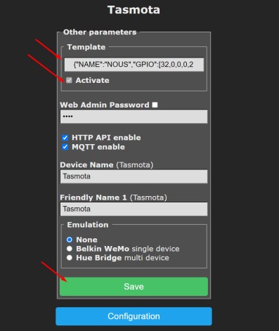 |
| 11 | To reset the device to factory settings, you need: Plug and unplug the device 6 times and leave it on for the 7th – the LED should start flashing, it means it is ready to connect again; if there is access to the web interface, then type ” reset 1″ in the console and press “enter” |
| 12 | To connect the device to smart home systems using the Matter protocol , read the following information: https://tasmota.github.io/docs/Matter/ |
Tasmota is a highly extensible and flexible application that can be integrated with:
Alexa, AWS IoT, Domoticz, Home Assistant, Homebridge, HomeSeer, IP Symcon, KNX, NodeRed, nymea, OctoPrint, openHAB, Otto, IOBroker, Mozilla WebThings Adapter, SmartThings, Tasmohab, Homematic ip тощо. for more information see here: https://tasmota.github.io/docs/Integrations/
![]()
Documents / Resources
 | NOUS B2T WiFi Tasmota Switch Module [pdf] Instruction Manual NOUS-B2T-1660, B2T WiFi Tasmota Switch Module, B2T, WiFi Tasmota Switch Module, Tasmota Switch Module, Switch Module, Module |