![]() TA Fast-Fit 4 Prefabricated Solution for Terminal Units
TA Fast-Fit 4 Prefabricated Solution for Terminal Units
Instruction Manual
TA Fast-Fit 4 Prefabricated Solution for Terminal Units
9696-32-800-480 UK
12.2022


NOTE! Assembly example, product components may vary.

NOTE!
It is not allowed to hold the TA Fast-Fit 4 assembly, during installation, on other places then indicated by the wrenches in the illustration.
Max. torque ≤ 50 Nm (36.9 lbf.ft.)
EMO T / EMO TM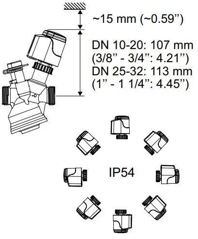 TA-Slider 160
~15 mm (~0.59’’)
DN 15-20: 119 / 128 / 145 mm *
(1/2’’ – 3/4’’: 4.68’’ / 5.04’’ / 5.71’’) *
DN 25: 130 / 139 / 156 mm *
(1’’: 5.12’’ / 5.47’’ / 6.14’’) *
DN 32: 133 / 142 / 159 mm *
(1 1/4’’: 5.24’’ / 5.59’’/ 6.26’’) * *) Depending on version
| Normal operation | Back flushing |
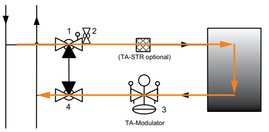 |  |
| 1. Open 2. Closed 3. Open 4. Open | 1. Closed 2. Open 3. Open 4. Open |
| Flushing the distribution system | Forward flushing |
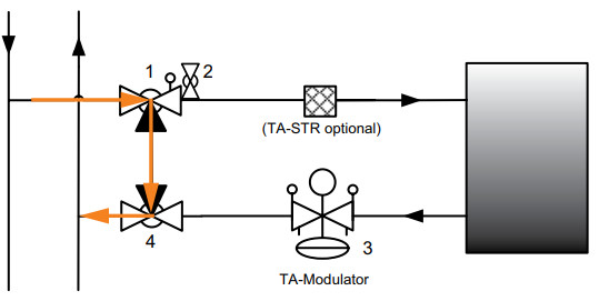 |  |
| 1. Closed 2. Closed 3. Open 4. Closed | 1. Open 2. Open 3. Closed 4. Open |

TA-Modulator / TA-COMPACT-P

STAV
Fixed orifice double regulating valve
Installation
- the valve must be installed in a straight run of pipe of the same nominal size, with the flow arrow on the valve body pointing in the direction of flow.
- the piping in the inlet side is straight and has a minimum length according to Fig. 1.
- after cutting the pipe, the end must be deburred before fitting it to the valve.
N.B. If using pipes smaller than valve size (also when using KOMBI) – contact IMI Hydronic Engineering.Installation layout
Installation layout
N.B. To ensure flow measurement accuracy it is essential that the piping in the inlet side is straight and has a minimum length according to Fig. 1.
Pipe cutting
After cutting the pipe, the end must be deburred before fitting it to the valve. Failure to carry out this procedure may lead to errors in flow measurement accuracy.
Setting
Flow regulation is achieved by adjusting the valve setting until the required flow rate is obtained. The handwheel will indicate the valve setting.
For maximum limit of the valve, use a 3 mm Allen key, turn the inner spindle clockwise to its end position.
Valve setting indicator
The valves operate from closed to fully open with 4 complete turns of the handwheel. The handwheel indicates the valve setting by means of digits appearing in outer (black) and inner (red) windows. The digit in the outer window indicates the number of full turns. The digit in the inner window indicates tenths of a turn. We reserve the right to introduce technical alterations without prior notice.
Documents / Resources
 | IMI Hydronic Engineering TA Fast-Fit 4 Prefabricated Solution for Terminal Units [pdf] Instruction Manual TA Fast-Fit 4 Prefabricated Solution for Terminal Units, TA Fast-Fit 4, Prefabricated Solution for Terminal Units, Terminal Units, Prefabricated Solution |