Holybro PM07 Pixhawk 4 Power Module

Quick Start
The Power Management Board (PM Board) serves the purpose of a Power Module as well as a Power Distribution Board. In addition to providing regulated power to Pixhawk 4 and the ESCs, it sends information to the autopilot about battery’s voltage and current supplied to the flight controller and the motors.
To power Pixhawk 4, connect one of the PWR ports of PMB to one of the POWER bricks of Pixhawk 4. The PMB’s input 2~12S will be connected to your LiPo battery. The connections of PMB, including power supply and signal connections to the ESCs and servos, are explained in the table below. Note that the PMB does not supply power to the servos via + and – pins of FMU PWM-OUT. The image below shows the power management board provided with Pixhawk 4.

- Note: If using a plane or rover, the 8 pin power (+) rail of FMU PWM-OUT will need to be separately powered in order to drive servos for rudders, elevons etc. To do this, the power rail needs to be connected to a BEC equipped ESC or a standalone 5V BEC or a 2S LiPo battery. Be careful with the voltage of servo you are going to use here.
PIN & Connector | Function |
| I/O PWM-IN | See table below for connection to Pixhawk 4 |
| M1 | I/O PWM OUT 1: connect signal wire to ESC of motor 1 here |
| M2 | I/O PWM OUT 2: connect signal wire to ESC of motor 2 here |
| M3 | I/O PWM OUT 3: connect signal wire to ESC of motor 3 here |
| M4 | I/O PWM OUT 4: connect signal wire to ESC of motor 4 here |
| M5 | I/O PWM OUT 5: connect signal wire to ESC of motor 5 here |
| M6 | I/O PWM OUT 6: connect signal wire to ESC of motor 6 here |
| M7 | I/O PWM OUT 7: connect signal wire to ESC of motor 7 here |
| M8 | I/O PWM OUT 8: connect signal wire to ESC of motor 8 here |
| FMU PWM-IN | See table below for connection to Pixhawk 4 |
| FMU PWM-OUT | If FMU PWM-IN is connected to Pixhawk 4, connect signal wires to ESC or signal, +, – wires to servos here |
| CAP&ADC-OUT | Connect to CAP & ADC IN port of Pixhawk 4 |
| CAP&ADC-IN | CAP & ADC input: See back of the board for pinouts |
| B+ | Connect to ESC B+ to power the ESC |
| GND | Connect to ESC Ground |
| PWR1 | 5v output 3A, connect to Pixhawk 4 POWER 1 |
| PWR2 | 5v output 3A, connect to Pixhawk 4 POWER 2 |
| 2~12S | Power Input, connect to 2~12S LiPo Battery |
Note: Depending on your airframe type, refer to Airframe Reference to connect I/O PWM OUT and FMU PWM OUT ports of Pixhawk 4 to PM board. MAIN outputs in PX4 firmware map to I/O PWM OUT port of Pixhawk 4 whereas AUX outputs map to FMU PWM OUT of Pixhawk 4. For example, MAIN1 maps to IO_CH1 pin of I/O PWM OUT and AUX1 maps to FMU_CH1 pin of FMU PWM OUT. FMU PWM-IN of PM board is internally connected to FMU PWM-OUT, which is used to drive servos (e.g. aileron, elevator, rudder, elevon, gear, flaps, gimbal, steering). I/O PWM-IN of PM board is internally connected to M1-8, which is used to drive motors (e.g. throttle in Plane, VTOL and Rover).
The following table summarizes how to connect Pixhawk 4’s PWM OUT ports to PMB’s PWM-IN ports, depending on the PX4 Airframe Reference. You can find this reference online in PX4 User guide.
PX4 Airframe Reference | Connection between Pixhawk 4 –> PMB |
| MAIN: motor | I/O PWM OUT –> I/O PWM IN |
| MAIN: servo | I/O PWM OUT –> FMU PWM IN |
| AUX: motor | FMU PWM OUT –> I/O PWM IN |
| AUX: servo | FMU PWM OUT –> FMU PWM IN |
The pinout: of Pixhawk 4’s power ports is shown below. The CURRENT signal should carry an analog voltage from 0-3.3V for 0-120A as default. The VOLTAGE signal should carry an analog voltage from 0-3.3V for 0-60A as default. The VCC lines have to offer at least 3A continuous and should default to 5.1V. A lower voltage of 5V is still acceptable, but discouraged.
Power 1, Power 2 port
Pin | Signal | Volt |
| 1 (red) | VCC | +5V |
| 2 (blk) | VCC | +5V |
| 3 (blk) | CURRENT | +3.3V |
| 4 (blk) | VOLTAGE | +3.3V |
| 5 (blk) | GND | GND |
| 6 (blk) | GND | GND |
Specifications: PCB Current: total 120A outputs (MAX)
UBEC 5v output current :3A
UBEC input voltage : 7~51v (2~12s LiPo)
Dimensions:68*50*10 mm
Mounting: Holes:45*45mm
Weight: 40.3g
Make the PM07 show the quantity of electric charge of your battery Mission Planner setup:
- Connect PM07 to the battery, also connect it to Mission Planner via USB.
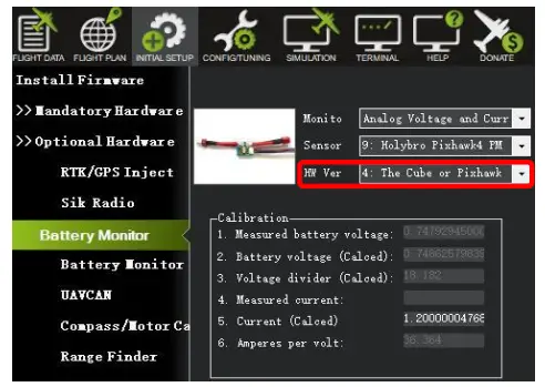
- Click “INITIAL SETUP” and come to the menu “Battery Monitor”.
- Make “Monito” into “Analog Voltage and Current”.
- Make “Sensor” into “9: Holybro Pixhawk4 PM”.
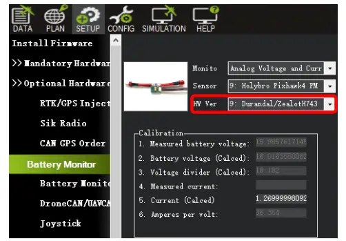
- Make “HW Ver: “The Cube or Pixhawk” pixhawk4,pixhawk4mini,pix32v5,pix32″ “HW Ver: DurandalDurandal”
- Input “18.182” into Voltage divider (Calced).
- Input “36.364” into “Amperes per volt”.
- Disconnect and reconnect it to finish the setting up.”Measured battery voltage” shows the current quantity of electric charge of the battery.
- HW Ver: “The Cube or Pixhawk” (pixhawk4,pixhawk4mini,pix32v5,pix32)
- HW Ver: Durandal(Durandal).Or you can desigante it in the Full Parameter List
The XT60 plug and 12AWG wire that PM06 comes with is rated for 30A continuous current and 60A instantaneous current (<1 minute). If a higher current is being used, the plug type and wire size should be changed accordingly. The specifications and models
| Plug specification | wire size | Rated current: (4 hours, temperature rise <60 degrees) | Max current: (1 minute, temperature rise <60 degrees) |
| XT60 | 12AWG | 30A | 60A |
| XT90 | 10AWG | 45A | 90A |
| XT120 | 8AWG | 60A | 120A |
Package includes:
1x PM07 board
1x 80mm XT60 connector wire
1x Electrolytic capacito: 220uF 63V(installed)
1x JST GH 10P Cable
1x JST GH 8P Cable
1x JST GH 6P Cable
Holybro is a registered trademark of Holybro, registered in the U.S. and other countries. ©Copyright 2018 Holybro. All Rights Reserved.
CUSTOMER SUPPORT

Documents / Resources
 | Holybro PM07 Pixhawk 4 Power Module [pdf] User Guide PM07 Pixhawk 4 Power Module, PM07, Pixhawk 4 Power Module, 4 Power Module, Power Module |


