goBILDA Element-6 Radio Control System Mode 2

Element-6 Radio Control System (Mode 2)
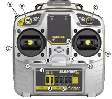
| A | Hi/Lo Toggle Switch | I | Mix Mode Switch | |
| B | Channel 5, 3-Position Toggle Switch | J | Channel Mixing Switch | |
| C | Channel 6, Proportional Dial | K | Servo Reverser Switches | |
| D | Power Switch | L | Left Gimbal | |
| E | Trim Switch, Left Gimbal, Y Axis | M | Right Gimbal | |
| F | Trim Switch, Left Gimbal, X Axis | |||
| G | Trim Switch, Right Gimbal, Y Axis | |||
| H | Trim Switch, Right Gimbal, X Axis | |||
Specs
- Transmitter Power ≤ 70mW
- Transmission Frequency: 2.401 – 2.479GHz
- Range: Up to 800 Meters (2625 Feet) with direct line of sight.
CH MIX: This switch enables or disables mixing. When set to “NO”, MIX MODE is ignored and no mixing occurs.
MIX MODE A: In MIX MODE A, the X-axis of the left gimbal and the Y-axis of the right gimbal are mixed and output to channels 2 and 4.
MIX MODE B: In MIX MODE B, the X and Y axes of the right gimbal are mixed and output to channels 1 and 2.
Trim Switches: For each axis, on each gimbal, there is a trim switch which allows you to adjust the signal that is sent when the gimbal is centered. To achieve this, the entire sigal range is shifted up or down 10µ seconds for each beep of the switch. A long beep means that the signal is either completely centered or has reached the max that it can be shifted in a particular direction.
SERVO REVERSER Switches
These four switches provide a convenient way to invert the PWM signal output for the indicated channels. Regardless of mixing or PWM range limiting, the number next to each of these switches correlates to the channel number on the receiver. This allows you to change the direction a servo rotates relative to gimbal travel. It is also useful when used with motor controllers, allowing you to change the direction a motor rotates relative to gimbal travel.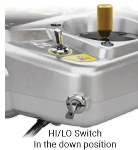
- HI/LO Switch: When this switched is toggled down (LO) it limits the PWM Range that is output on channels 1, 2 & 4 to half that of their normal range. This can be used to limit the travel of servos, or decrease the top speed of motors (when the reciever is connected to a motor controller).
- RF Light: This light indicates that the transmitter is sending a signal. It does not indicate connection to a receiver or movement of the gimbals.
- Transmitter Power: The transmitter uses four “AA” batteries.
- Receiver: Input Voltage: 6V nominal (3.5-7.4V)
Note: Power can be supplied through any of the + – pins. Channel: 7 PWM channels, 1 M.Bus Port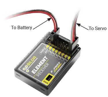
Pairing the Receiver
- Start with the transmitter and receiver powered off.
- Connect power to the receiver. The receiver’s orange LED will blink slowly.
- Press and release the Bind button on the receiver with a small screwdriver or pen. The receiver’s orange LED will blink quickly.
- Ensure the left gimbal on the transmitter is all the way down.
- Turn on the transmitter.
- The orange LED on the receiver will stop blinking and turn on solid when paired.
M.BUS (aka S.BUS): M.Bus is a communication protocol that allows you to use one physical port on the receiver to control multiple servos. Each servo must be M.Bus capable and programmed to be on a particular digital channel.
Documents / Resources
 | goBILDA Element-6 Radio Control System Mode 2 [pdf] User Manual Element-6 Radio Control System Mode 2, Element-6 |


