Danfoss OS7MT Hybrid Modbus
Operating Guide
iC7-Hybrid Modbus
Modbus TCP OS7MT
Introduction and Safety
Purpose of the Operating Guide
This operating guide provides information about configuring the system, controlling the drive or power converter, accessing parameters, programming, troubleshooting, and some typical application examples.
The operating guide is intended for use by qualified personnel, who are familiar with the iC7 drives and power converters, Modbus technology, and the PC or PLC that is used as a master in the system.
Read the instructions before configuring Modbus, and follow the procedures in this guide.
Additional Resources
Additional resources are available to help understand the features, and safely install and operate the iC7 series products:
- Safety guides, which provide important safety information related to installing iC7 series drives and power converters.
- Installation guides, which cover the mechanical and electrical installation of drives, power converters, or functional extension options.
- Design guides, which provide technical information to understand the capabilities of the iC7 series drives or power converters for integration into motor control and monitoring systems.
- Operating guides, which include instructions for control options, and other components for the drive.
- Application guides, which provide instructions on setting up the drive or power converter for a specific end use. Application guides for application software packages also provide an overview of the parameters and value ranges for operating the drives or power converters, configuration examples with recommended parameter settings, and troubleshooting steps.
- Facts Worth Knowing about AC Drives, available for download on www.danfoss.com.
- Other supplemental publications, drawings, and guides are available at www.danfoss.com.
Latest versions of Danfoss product guides are available for download at https://www.danfoss.com/en/service-and-support/documentation/.
Safety Symbols
The following symbols are used in Danfoss documentation.
![]() DANGER
DANGER
Indicates a hazardous situation which, if not avoided, will result in death or serious injury.
![]() WARNING
WARNING
Indicates a hazardous situation which, if not avoided, could result in death or serious injury.
![]() CAUTION
CAUTION
Indicates a hazardous situation which, if not avoided, could result in minor or moderate injury.
NOTICE
Indicates information considered important, but not hazard-related (for example, messages relating to property damage).
The guide also includes ISO warning symbols related to hot surfaces and burn hazard, high voltage and electrical shock, and referring to the instructions.
 | ISO warning symbol for hot surfaces and burn hazard |
 | ISO warning symbol for high voltage and electrical shock |
 | ISO action symbol for referring to the instructions |
Qualified Personnel
Correct and reliable transport, storage, installation, operation, and maintenance are required for the trouble-free and safe operation of the product. Only qualified personnel are allowed to install and operate this equipment.
Qualified personnel are defined as trained staff, who are authorized to install, commission, and maintain equipment, systems, and circuits in accordance with pertinent laws and regulations. Also, the qualified personnel must be familiar with the instructions and safety measures described in this guide.
Safety Precautions
| WARNING | |
| HIGH VOLTAGE Drives and power converters contain high voltage when connected to AC mains input, DC supply, or load sharing. Failure to perform installation, startup, and maintenance by qualified personnel can result in death or serious injury.
|
WARNING
UNINTENDED START
When the drive or power converter is connected to the AC mains or connected on the DC terminals, the motor may start at any time, causing risk of death, serious injury, and equipment or property damage.
- Stop the drive or power converter before configuring parameters.
- Make sure that the drive or power converter cannot be started by an external switch, a fieldbus command, an input reference signal from the control panel, or after a cleared fault condition.
- Disconnect the drive or power converter from the mains whenever safety considerations make it necessary to avoid an unintended motor start.
- Check that the drive or power converter and any driven equipment are in operational readiness.
WARNING
DISCHARGE TIME
The drive or power converter contains DC-link capacitors, which can remain charged even when the drive or power converter is not powered. High voltage can be present even when the warning indicator lights are off. Failure to wait the specified time after power has been removed before performing service or repair work can result in death or serious injury.
- Stop the motor.
- Disconnect all power sources, including permanent magnet type motors.
- Wait for capacitors to discharge fully. The discharge time is specified on the drive or power converter product label.
- Measure the voltage level to verify full discharge.
NOTICE
LEAKAGE CURRENT HAZARD
Leakage currents exceed 3.5 mA. Failure to ground the drive or power converter properly can result in death or serious injury.
- Ensure that the minimum size of the ground conductor complies with the local safety regulations for high touch current equipment.
WARNING
EQUIPMENT HAZARD
Contact with rotating shafts and electrical equipment can result in death or serious injury.
- Ensure that only trained and qualified personnel perform installation, start-up, and maintenance.
- Ensure that electrical work conforms to national and local electrical codes.
- Follow the procedures in this guide.
CAUTION
INTERNAL FAILURE HAZARD
An internal failure in the drive or power converter can result in serious injury when the drive or power converter is not properly closed.
Ensure that all safety covers are in place and securely fastened before applying power.
Abbreviations
Table 1: Abbreviations
| Abbreviation | Definition |
| ACD | Address Conflict Detection |
| BOOL | Boolean |
| CTW | Control word |
| DCP | Discovery and configuration protocol |
| DHCP | Dynamic host configuration protocol |
| EMC | Electromagnetic compatibility |
| I/O | Input/Output |
| Abbreviation | Definition |
| IP | Internet protocol |
| CP | Control panel |
| LED | Light-emitting diode |
| LLDP | Link layer discovery protocol |
| LSB | Least significant bit |
| MAV | Main actual value |
| MEI | Modbus encapsulated interface |
| MRV | Main reference value |
| MSB | Most significant bit |
| PC | Personal computer |
| PCD | Process channel data |
| PLC | Programmable logic controller |
| PNU | Parameter number |
| PPO | Process parameter object |
| REF | Reference |
| SNMP | Simple network management protocol |
| STW | Status word |
| VLAN | Virtual LAN |
Trademarks
Ethernet® is a registered trademark of Xerox Corporation.
MODBUS® is a registered trademark of Schneider Electric USA, Inc.
Version History
This guide is regularly reviewed and updated. All suggestions for improvement are welcome. The original language of this guide is English.
Table 2: Version History
| Version | Remarks |
| AQ485333770758, version 0101 | Initial version. |
Product Overview
Modbus Features and Technical Data
Fieldbus options for iC7 are integrated in the control board. Fieldbuses are enabled on communication interfaces X1 and X2 only. Modbus TCP is offered as standard, and other protocols such as PROFINET RT can be selected in the configurator when ordering a drive or power converter, or alternatively, they can be activated later by a proof-of-purchase token.
Table 3: Modbus Model Codes
| Model code | Description |
| +BAMT | Modbus TCP OS7MT |
Modbus is a communication protocol developed by Modicon for sending information between electronic devices. In Modbus TCP, the device requesting the information is called the Modbus client, and the devices supplying information are called Modbus servers.
The client can also write information to the server. Modbus is typically used to transmit signals from instrumentation and control devices back to a main controller or data gathering system.
Modbus does not feature a dedicated data channel, and therefore Modbus requests are handled as acyclic.
Table 4: Modbus TCP Features
| Feature | Technical data |
| Cyclic response | 5 ms response time per variable (read/write non-persistent storage) |
| Supported Modbus objects | Coils (1 bit): Read-write |
| Input register (16 bits): Read-only | |
| Holding register (16 bits): Read-write | |
| Connection | PRP (Parallel Redundancy Protocol) |
| LLDP/SNMP | |
| IPv4 | |
| Addressing mode: DCP, STATIC, DHCP/BOOTP | |
| Configuration | MyDrive® Insight |
iC Hybrid Profile
Overview
The iC Hybrid profile is used in the iC7 series with the Grid Converter and DC/DC Converter applications.
Control Word
Table 5: Control Word Bits in iC Hybrid Profile
| Bit | Name | Description |
| 0 | Switch On Enabled | 0: Pre-charging(1), closing the main circuit breaker(1), and running are prevented or interrupted. If the main circuit breaker is closed, it is opened(1). 1: Pre-charging(1), closing the main circuit breaker(1), and running are not prevented or interrupted. |
| 1 | MCB Close Enabled | 0: Closing the main circuit breaker is prevented(1) or the main circuit breaker is opened(1), and running is prevented or interrupted. 1: Closing the main circuit breaker is not prevented(1). |
| 2 | Quick Stop | 0: Activate Quick Stop. 1: Do not activate Quick Stop. |
| 3 | Start | 0: Stop the unit if it is running, or stop the startup sequence if it is not completed. 1: Initiate the startup sequence (DC-link precharging(2), closing the main circuit breaker(2), and start running), or keep the unit running. |
| 4 | Pre-charge | 0: Stop the DC-link precharging, if ongoing. 1: Start or continue the DC-link precharging. |
| 5 | – | Reserved |
| 6 | – | Reserved |
| 7 | Warning/Fault Reset | 0: No action. 1: Reset active warnings/faults. |
| 8 | – | Reserved |
| 9 | – | Reserved |
| 10 | Data Valid | 0: Ignore the current incoming process data values, instead use the last processed value when the Data Valid bit was true. 1: Use the current incoming process data values. |
| 11 | Watchdog | Incoming watchdog bit. |
| 12 | Vendor Specific Bit 1 | 0: Deactivate vendor specific function using digital input/ output virtual slot 6412. 1: Activate vendor specific function using digital input/ output virtual slot 6412. |
| 13 | Vendor Specific Bit 2 | 0: Deactivate vendor specific function using digital input/ output virtual slot 6413. 1: Activate vendor specific function using digital input/ output virtual slot 6413. |
| Bit | Name | Description |
| 14 | Vendor Specific Bit 3 |
|
| 15 | Vendor Specific Bit 4 |
|
- If controlled by the grid converter unit.
- If applicable.
Status Word
Table 6: Status Word Bits in iC Hybrid Profile
| Bit | Name | Description |
| 0 | Ready to Switch On | 0: Not ready to switch on. 1: Ready to switch on. |
| 1 | Ready to Run |
|
| 2 | Running | 0: Converter is not modulating. 1: Converter is modulating. |
| 3 | Fault |
|
| 4 | – | Reserved |
| 5 | Quick Stop |
|
| 6 | – | Reserved |
| 7 | Warning |
|
| 8 | – | Reserved |
| 9 | Control by PLC | 0: The active control place is not fieldbus. 1: The active control place is fieldbus. |
| 10 | – | Reserved |
| 11 | Run Enabled |
|
| 12 | – | Reserved |
| Bit | Name | Description |
| 13 | – | Reserved |
| 14 | – | Reserved |
| 15 | Watchdog | Outgoing fieldbus watchdog bit. |
Network Topologies
Overview
Communication interface X1/X2 is used for fieldbus connection.
The communication interface in the iC7 drives and power converters has 2 Ethernet ports (X1 and X2) and an embedded switch with 2 Ethernet RJ45 connectors. It has 1 MAC and IP address, and is considered a single device in the network. The communication interface supports 3 network topologies:
- Line topology
- Star topology
- Ring topology
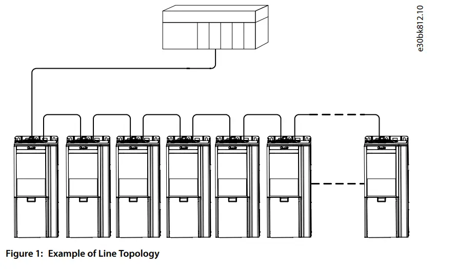
Line Topology
In many applications, line topology enables simpler cabling and the use of fewer Ethernet switches. Observe network performance and the number of devices in a line topology. Too many devices in a line may exceed network update time limits.
NOTICE
When line topology is used, take precautions to avoid timeout in the PLC when more than 8 drives or power converters are installed in series. Each drive or power converter in the network adds a small delay to the communication due to the built-in Ethernet switch. When the update time is too short, the delay can lead to a timeout in the PLC.
Set the update time as shown in the table. The numbers given are typical values and can vary from installation to installation.
Number of units connected in series Minimum update time [ms]
- <8 2
- 8–16 4
- 16–32 8
- 33–50 16
- >50 Not recommended
NOTE: Using tools such as MyDrive® Insight may influence system performance in a line topology.
NOTICE
Installing drives or power converters of different current ratings in line topology may result in unwanted power-off behavior.
Mount the drives or power converters with the longest discharge time first in the line topology. In normal operation, the drives or power converters with bigger current ratings have a longer discharge time.
Star Topology
In a star network, all devices are connected to the same switch or switches. Star topology reduces the damage caused by a single cable failure. In a star topology, a single cable failure affects a single device instead of all devices in the network. In many applications, this topology enables simpler cabling depending on the location and distance of the device.

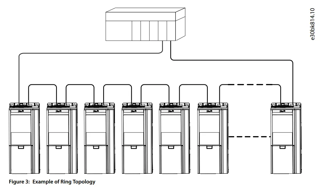
Ring Topology
Ring topology enables the same simpler cabling and reduced cabling costs as line topology, but also reduces the damage caused by a single cable failure in a similar manner as star topology.
NOTICE
When ring topology is used, take precautions to avoid timeout in the PLC when more than 8 drives or power converters are installed in series. Each drive or power converter in the network adds a small delay to the communication due to the built-in Ethernet switch. When the update time is too short, the delay can lead to a timeout in the PLC.
Set the update time as shown in the table. The numbers given are typical values and can vary from installation to installation.
Number of units connected in series Minimum update time [ms]
- <8 2
- 8–16 4
- 16–32 8
- 33–50 16
- >50 Not recommended
The ring topology protocol depends on the protocol in use. Modbus uses the parallel redundancy protocol (PRP). PRP is a layer 2 network protocol that enables a redundant topology in an Ethernet network. PRP provides uninterrupted switchovers in failure situations, and is independent of the application.
For more information on configuring parallel redundancy protocol (PRP), see 5.3 Configuring Parallel Redundancy Protocol.
Modbus Data Mapping
Mapping Modbus Coils
A Modbus coil is a single-bit binary data item which can be both read and written. Coils can be mapped to specific bits in a parameter by using the customization feature in MyDrive® Insight.
Only bit-type parameters can be mapped to coils. The source type must be INT, UINT, USINT DINT, UDINT, WORD, or BOOL.
- In MyDrive® Insight, go to Customization > Live > MODBUS > Coils.
- To add a single coil, click the + Add Item icon.
- To map multiple coils to a single parameter, click the – Add Multiple Itemsicon.
Table 7: Coil Mapping Settings
| Column | Description |
| Location | Refers to the coil number. Coils are mapped from address 00000–0FFFF. |
| Reference type |
|
| Reference | The name of the mapped parameter, feature, or event. |
| Source type | Data type of mapped parameter |
| Index | Index pointer for array parameters |
| Bit number | Mapped bit number of the selected parameter. 0 refers to the 1st bit. |
| Permissions | Setting Read/Write permissions for each coil. |
| Watchdog | Watchdog1: Process data timeout watchdog. Timeout time is configured in parame- ter Process Data Timeout Delay (parameter number 1340). The Watchdog timer is (re)triggered when writing to the mapped coil or register. Watchdog2: Not used |
Mapping Modbus Holding Registers
A Modbus holding register is a bit binary data item which can be both read and written. Registers can be mapped to a specific parameter by using the customization feature in MyDrive® Insight. The first 19 holding registers are pre-mapped or reserved and cannot be changed. From location 20 onwards, registers can be mapped freely.
IMPORTANT: The parameter mapped to 1 register can only be remapped to another register.
NOTICE
A mismatch between the datatype and register type issues a warning of possible data loss.
| Location | Reference type | Reference (parameter number) |
| 2 | Parameter | Fieldbus Control Word (1335) |
| 3 | Parameter | Reserved |
| Location | Reference type | Reference (parameter number) |
| 4 | Parameter | Reserved |
| 5 | Parameter | Reserved |
| 6 | Parameter | Reserved |
| 7 | Parameter | Reserved |
| 8 | Parameter | Reserved |
| 9 | Parameter | Reserved |
| 10 | Parameter | Fieldbus Status Word (1307) |
| 11 | Parameter | Reserved |
| 12 | Parameter | Reserved |
| 13 | Parameter | Reserved |
| 14 | Parameter | Reserved |
| 15 | Parameter | Reserved |
| 16 | Parameter | Reserved |
| 17 | Parameter | Reserved |
| 18 | Parameter | Reserved |
| 19 | Parameter | Reserved |
| 20 | … | … |
| … | … | … |
- In MyDrive® Insight, go to Customization > Live > MODBUS > Holding Registers.
- To add a single register, click the + Add Item icon.
- To add multiple registers, click the – Add Multiple Items icon.
Table 8: Holding Register Settings
| Column | Description |
| Location | Refers to the register number. Coils are mapped from address 00000–0FFFF. |
| Reference type |
|
| Reference | The name of the mapped parameter, feature, or event. Value for Constant type. |
| Source type | Data type of mapped parameter. |
| Index | Index pointer for array parameters. |
| Length | Number of bytes for string-type parameters. |
| Column | Description |
| Register type | Data type of the mapped parameter. By default, the Customizer selects a regis- ter type that matches the data type of the selected parameter. |
| Scaling | Scales the parameter value on the Modbus interface by dividing it by the scal- ing value entered. |
| Unit | Unit of the mapped parameter |
| Permissions | Setting Read/Write permissions for each register. |
| Watchdog | Watchdog1: Process data timeout watchdog. Timeout time is configured in pa- rameter Process Data Timeout Delay (parameter number 1340). The Watchdog timer is triggered when writing to the mapped coil or register. Watchdog2: Not used |
Mapping parameter of the REAL 32-bit datatype results in 2 consecutive register mappings.
Table 9: Example of a Holding Register Mapping
| Location | Reference type | Reference (parameter number) | Source type | Register type |
| 20 | Parameter | Converter Output Current (9000) | REAL | Two Consecutive Floating point |
| 22 | Parameter | Heat Sink Temperature (2950) | REAL | Two Consecutive Floating point |
| … | … | … | … | … |
Events from the device event log can be mapped into holding registers, starting from the most recent event. Each event results in six consecutive register mappings.
Table 10: Example of an Event Register Mapping
| Register | Description | Format |
| n | Timestamp | Seconds/milliseconds [SS.SSS](1) |
| n+1 | Hours/Minutes [HHMM](1) | |
| n+2 | Month/Day [MMDD](1) | |
| n+3 | Year [YYYY](1) | |
| n+4 | Event Type |
|
| n+5 | Event Code | See the application guide for the applica- tion software in use. |
Mapping Modbus Input Registers
A Modbus input register is a 16-bit read-only value.
Input registers can be mapped to specific parameters by using the customization feature in MyDrive® Insight.
- In MyDrive® Insight, go to Customization > Live > MODBUS > Coils.
- To add a single register, click the + Add Item icon.
- To add multiple registers, click the – Add Multiple Items icon.
Table 11: Coil Mapping Settings
| Column | Description |
| Location | Refers to the coil number. Coils are mapped from address 00000–0FFFF. |
| Reference type |
|
| Reference | The name of the mapped parameter, feature, or event. Value for Constant type. |
| Source type | Data type of mapped parameter |
| Index | Index pointer for array parameters. |
| Length | Length as number of bytes for string-type parameters. |
| Register type | Data type of the mapped parameter. By default, the Customizer selects a register type that matches the data type of the se- lected parameter. |
| Scaling | Scales the parameter value on the Modbus interface by dividing it by the scaling value entered. |
| Unit | Unit of the mapped parameter. |
Setting Permissions
Permissions can be set either in the Permissions column in the mapping view, or in the Permissions view in MyDrive® Insight.
- In MyDrive® Insight, go to Customization > Live > MODBUS > Permissions.
- Set the Read/Write permission for coils and registers:
- By using the Permissions column in the mapping view.
- By using the Permissions view in MyDrive® Insight.
IMPORTANT: Individual settings for each coil or register overwrite the default selection ALL. If the permission is not set for a specific coil, or register, the selection ALL is predominant.
Saving Modbus Configuration to a Device
After the Modbus mapping is finalized, the configuration can be saved as a new project or added to an existing MyDrive® Insight project.
- To save a configuration, click the Save icon.
- To deploy a configuration directly into a device, click the Download icon to create and save an export package (*.vpkg).
- After exporting the configuration, update and power cycle the device with the exported software package.
Table 12: Example of an Export Package
| Package name Default: Fully Qualified Domain Name) | ### |
| Package version (Default: 1.0.0) | ### |
Fieldbus Cable Connections
Prerequisites for Installation
Communication interfaces are integrated in the control board in iC7 drives and power converters.
The position of the connections differs based on the control board concept and frame, for example. For more information on the location of the connections, cabling, and shielding, refer to the product-specific design guide.
Communication Interface X1/X2 in Frames FA02–FA12
The communication interface is on the top of the frequency converter as shown in Figure 4. Industrial-grade RJ45 connectors are recommended for optimal connection. A combined shield/fixing plate, the Fieldbus EMC plate, is available as an accessory to strengthen the mechanical fixation of the cables. For information on ordering the EMC plate, refer to the product-specific design guide.

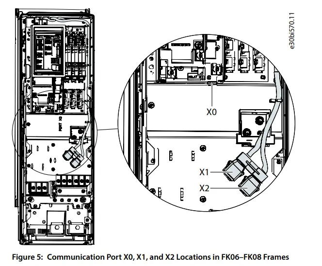
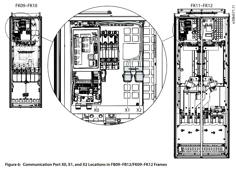
Communication Interface X1/X2 in Frames FB09–FB12/FK06–FK12
The communication interface ports are located inside the frequency converter. The position of the ports and the recommended wiring path are shown in Figure 5 and Figure 6.
Communication Interface X1/X2 in System Modules
For systems that use system modules, the communication interface ports are located at the bottom facing side of the modular control unit as shown in Figure 7.
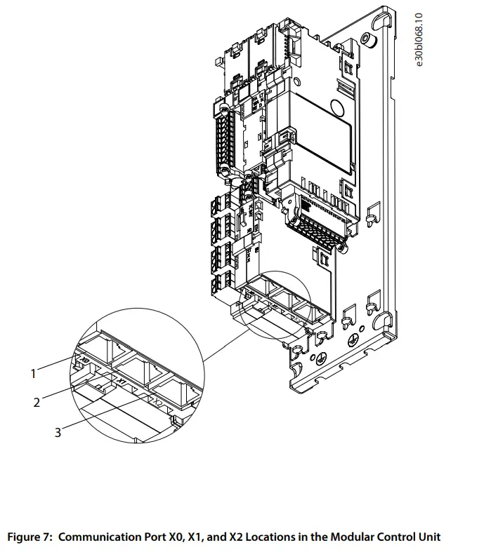 Ethernet port (X0)
- Ethernet port (X1)
- Ethernet port (X2)
EMC-compliant Installation
Overview
To obtain an EMC-compliant installation, follow the instructions provided in the product-specific design guide and the installation guide included in the shipment.
Grounding
- Ensure that all stations connected to the fieldbus network are connected to the same ground potential. When distances between the stations in a fieldbus network are long, connect the individual station to the same ground potential. Install equalizing cables between the system components.
- Establish a grounding connection with low HF impedance, for example, by mounting the unit on a conductive backplate.
- Keep the ground wire connections as short as possible.
Cable Routing
For more information on cabling, refer to the product-specific design guide and installation guide included in the shipment.
NOTICE
EMC INTERFERENCE
Failure to isolate fieldbus communication, motor, and brake resistor cables can result in unintended behavior or reduced performance.
- Use shielded cables for motor and control wiring, and separate cables for fieldbus communication, motor wiring, and brake resistor.
- A minimum of 200 mm (7.9 in) clearance between power, motor, and control cables is required. For power sizes above 315 kW (450 hp), increase the minimum distance to 500 mm (20 in).
NOTICE
CABLE ROUTING
When the fieldbus cable intersects a motor cable or a brake resistor cable, ensure that the cables intersect at an angle of 90°.
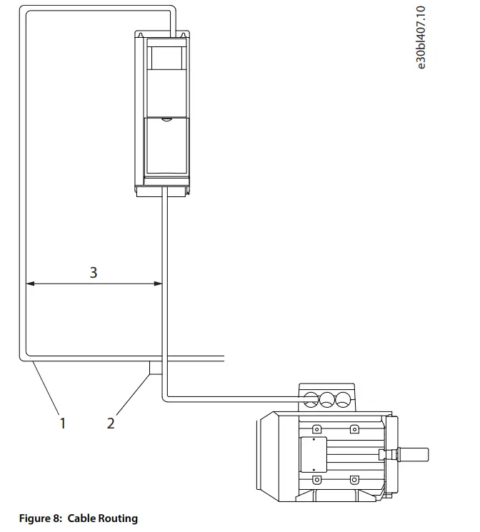 Fieldbus cable
- 90° intersection
- ≥200 mm (7.9 in) (≥ 500 mm (20 in) for power sizes >315 kW (450 hp))
Configuration
Connectivity Settings
Connectivity Settings for DC/DC Converter
General connectivity settings are in parameter group Parameters > Protections and Responses > Fieldbus Protections.
Table 13: Connectivity Parameters for DC/DC Converter
| Parameter | Parameter number | Value | Description |
| Fieldbus Fault Response | 1304 |
| Select the behavior when a fieldbus fault, for example loss of I/O connection occurs. |
| See Table 14 for descriptions of the events. | |||
| No Fieldbus Connection Response | 1305 |
| Select the response if there is no fieldbus connection. |
| See Table 14 for descriptions of the events. | |||
| Process Data Timeout Delay | 1340 | 50.0–3.4 x 1038 s (Default value: 1000.0 s) | Set a delay for the triggering of the Process Data Timeout event. If process data has not been updated within this de- lay time, the event is triggered. |
| Process Data Timeout Response | 1306 |
| Select the response in case there is no fieldbus connection. |
| See Table 14 for descriptions of the events. |
Table 14: Event Descriptions
| Value | Description |
| No response | The event is ignored. |
| Info | The event is logged in the event log. |
| Warning | The drive or power converter issues a warning. |
| Warning, Current Lim. Ramp – Persistent | A warning is issued, and the positive/negative active current limits are ramped to preset values. The current limit overrides stay active until the warning is acknowledged by a reset. |
| Fault | The drive or power converter issues a fault and modulation is stopped. |
Connectivity Settings for Grid Converter
General connectivity settings are in parameter group Parameters > Protections and Responses > Fieldbus Protections.
Table 15: Connectivity Parameters for Grid Converter
| Parameter | Parameter number | Value | Description |
| Fieldbus Fault Response | 1304 |
| Select the behavior when a fieldbus fault, for example loss of I/O connection occurs. |
| See Table 16 for descriptions of the events. | |||
| No Fieldbus Connection Response | 1305 |
| Select the response if there is no fieldbus connection. |
| See Table 16 for descriptions of the events. | |||
| Process Data Timeout Delay | 1340 | 50.0–3.4 x 1038 s (Default value: 1000.0 s) | Set the timeout time. If process data is not received within the time set, a process data timeout is triggered. |
| Process Data Timeout Response | 1306 |
| Select the response in case there is no fieldbus connection. |
| See Table 16 for descriptions of the events. |
Table 16: Event Descriptions
| Value | Description |
| No response | The event is ignored. |
| Info | The event is logged in the event log. |
| Warning | The drive or power converter issues a warning. |
| Warning, Current Lim. Ramp – Persistent | The drive or power converter issues a warning, and the positive/negative active current limits are ramped to preset values. The current limit overrides stay active until the warning is acknowledged by a reset. |
| Fault | The drive or power converter issues a fault and stops modulation. |
| Fault, Open MCB | The drive or power converter issues a fault, stops modulation, and opens the main circuit breaker. |
Configuring the Ethernet Interface
The X1 and X2 interfaces are internally connected with an Ethernet switch and share the same physical MAC layer, and the same IP settings apply to both interfaces. IPv4 settings are configured in MyDrive®Insight or in the control panel.
- Configure IPv4 settings.
- In MyDrive® Insight, go to Setup and Service > Interface configuration > Interface X1/X2 > IPv4 settings.
- In the control panel, navigate to parameter group 10.2 Communication Interfaces.
Table 17: IPv4 Settings
| Function | Value | Description |
| Interface X1/X2 MAC address | 00:1B:08:xx:xx:xx | The MAC address of interface X1/X2. The value is read-only. |
| IPv4 addressing method | Disable | Only link-local IP address in the 169.254.xxx.xxx range is active. |
| Static IP | A static IP address is entered manually. | |
| Automatic | IP address is assigned via a DHCP or BOOTP server. | |
| Requested IPv4 ad- dress | xxx.xxx.xxx.xxx | If Automatic is selected as the IPv4 addressing method and no DHCP/ BOOTP server is present, the X1/X2 interface automatically configures an IP address and subnet mask in the 169.254.xxx.xxx range. |
| Requested IPv4 sub- net mask | xxx.xxx.xxx.xxx | The requested IPv4 subnet mask for the interface. |
| Requested IPv4 gate- way address | xxx.xxx.xxx.xxx | Requested IPv4 gateway address for the interface. |
| Enable ACD | Enable | Request to enable or disable Address Conflict Detection for the inter- face. The change does not take effect before a power cycle is performed. If no conflicts are detected, ACD activity shows 0. If an address conflict occurs, the ACD activity shows 1, and the IPv4 interface reverts to an automatically assigned IP address in the 169.254.xxx.xxx range. |
| Disable (default) | ||
| DNS server 1, 2 | xxx.xxx.xxx.xxx | The user-requested Domain Name Server 1 for the interface (for man- ual IP addressing mode only). |
Table 18: Ethernet Port Configuration (X1/X2)
| Parameter name | Parameter number | Selections | Description | |
| Link Configuration X1 | 7048 | Auto negotiation | Configures the Ethernet | |
| link parameter | |||
| Link Configuration X2 | 7049 | |||
| 100 Mbps full duplex | ||||
| 100 Mbps half duplex |
Configuring Parallel Redundancy Protocol
Parallel Redundancy Protocol (PRP) is based on the parallel transmission of information by sending duplicate frames to 2 independent network infrastructures known as LAN A and LAN B. Each PRP node has a connection to each of the networks called double attached nodes (DAN) in PRP terminology.
PRP is implemented in the end devices only. The Ethernet switches in the network have no specific PRP capabilities. Standard devices with a single network interface are referred to as single attached nodes (SAN) and can by default be connected directly to 1 of the 2 networks. Alternatively, a SAN can be connected via a redundancy box (RedBox) that connects 1 or more SANs to both LAN A and LAN B networks.
- In MyDrive® Insight, go to Interface configuration > Ethernet Redundancy > PRP > Settings to configure PRP settings.
| Function | Value | Description |
| PRP Interface |
| Enables or disables PRP on the X1/X2 interface. |
| Enable VLAN |
| Enables or disables the transmissions of VLAN ID in the PRP supervision frames. |
| VLAN id | 0–65535 | VLAN ID used in PRP supervision frames when VLAN is enabled. |
2. In MyDrive® Insight, go to Interface configuration > Ethernet Redundancy > PRP > Status to check PRP status.
| Function | Description |
| Valid frames on LAN A | Valid frames received on LAN A with a valid sequence number. |
| Valid frames on LAN B | Valid frames received on LAN B with a valid sequence number. |
| Duplicate frames on LAN A | Valid frames received on LAN A dropped by duplicate detection. |
| Duplicate frames on LAN B | Valid frames received on LAN B dropped by duplicate detection. |
| Wrong LAN ID frames on LAN A | Valid frames received in LAN A with mismatching LAN ID. |
| Wrong LAN ID frames on LAN B | Valid frames received in LAN B with mismatching LAN ID. |
| Missing frames | The counter is incremented if there is a jump in the sequence number, |
| indicative of frame drop in both LANs. | |
| Out of sequence on LAN A | Valid and accepted frames received on LAN A with an unexpected sequence |
| number. | |
| Out of sequence on LAN B | Valid and accepted frames received on LAN B with an unexpected sequence |
| number. | |
| Out of sequence low on LAN A | Valid and accepted frames received on LAN A with a sequence number outside |
| duplicate window. | |
| Out of sequence low on LAN B | Valid and accepted frames received on LAN B with a sequence number outside |
| duplicate window. |
| Function | Description |
| Warning count on LAN A The counter is incremented if wrong frames or no PRP frames are received on LAN A. Warning count on LAN B The counter is incremented if wrong frames or no PRP frames are received on LAN B. | |
IMPORTANT: When configuring PRP, it is important to notice the assignment of the Ethernet ports:
- X1 = LAN A
- X2 = LAN B

Configuring Modbus Unit Identifier
In Modbus TCP, the device is addressed by its IP address, and the server ID is replaced by a single-byte unit identifier.
IMPORTANT: Value 255 (0xFF) must be used for the Modbus unit identifier (client ID).
When configuring the Modbus PLC client, a server ID, or a server address is used to address the serial Modbus RTU devices in the range of 1–247.
In Modbus TCP, an IP address and a single-byte unit identifier are used to address the device.
Configuring Modbus Data Settings
Use MyDrive® Insight or the control panel to select persistent storage and the byte and word order for Modbus communication.
- Using MyDrive® Insight or the control panel, navigate to parameter group Modbus TCP > Configuration.
| Parameter name | Parameter number | Value | Description |
| Persistent Storage | 7061 |
| Persistent Storage enables storing parameters written via Modbus in non-volatile memory. IMPORTANT: Enabling Persistent Storage causes a decrease in Modbus communication performance. |
| Byte Order | 7062 |
| Byte order of holding register. |
| Word Order | 7063 |
| Word order when mapping parameters (for example, 32- bit REAL) in multiple registers. |
Troubleshooting
Configuring Port Mirroring Settings
Enable or disable the port mirroring function for network troubleshooting with a network analyzer tool.
- In MyDrive® Insight, go to Setup and Service > Interface Configuration > Port Mirroring Settings.
| Function | Selections | Description |
| Source port |
| Frames are mirrored from this port. |
| Destination port |
| Frames are mirrored to this port. |
| Block RX from destination port | Enable/Disable | Device does not receive any frames from Destination Port when enabled. |
| Enable port mirroring | Enable/Disable | Enables the Port Mirroring feature. |
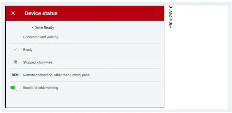
Identifying a Unit
The winking function makes the fieldbus indicator LEDs ST, X1, and X2 flash yellow to make it easy to identify a unit. The function is enabled in MyDrive® Insight.
- In MyDrive® Insight, click the device name in live mode.
- Select Device Status.
- To activate or deactivate the feature, click the toggle switch.
Fieldbus Indicator LEDs
The fieldbus indicator LEDs are in the top right corner of the control panel and the bottom part of the front-facing side of the modular control unit.

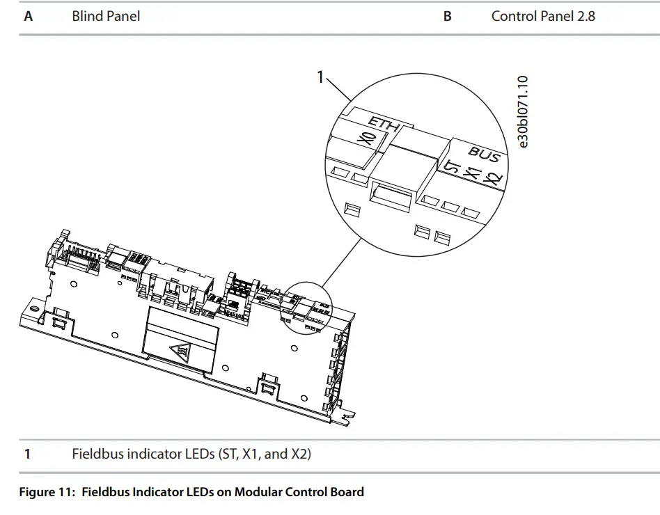
- The LED labeled ST shows the module status.
- The LED labeled X1 shows the network status on Ethernet port X1.
- The LED labeled X2 shows the network status on Ethernet port X2.
Table 21: Fieldbus Indicator LED Functions
| LED label | Status | LED pattern | Description |
| ST | Standby | Flashing green | No active Modbus TCP connections. |
| I/O connection ok | Solid green | Modbus TCP connection active. | |
| Lost Modbus connection | Flashing red | A Modbus TCP connection has failed, but 1 is still active (loss of I/O connection). | |
| Lost all Modbus connections | Steady red | Modbus TCP connections have failed (no I/O connection). | |
| X1/X2 | Link down | Off | – |
| Link up | Solid green | Ethernet link is active. | |
| Cable fault | Solid yellow | The device has detected an Ethernet cable fault. | |
| Collision | Flashing yel- low | Collision detected | |
| Duplicated IP address | Solid red | IP configuration errorModbus Features |
Data Objects
Table 22: Supported Object Types
| Object type | Access | Size |
| Coil | Read/write | 1 bit |
| Input register | Read only | 16 bits |
| Holding register | Read/write | 16 bits |
Function Codes
The function code of a message frame contains 8 bits. Valid codes are in the range of 1–FF. Use function codes to send messages between client and server. When a message is sent from a client to a server device, the function code tells the server which action to perform. When the server responds to the client, it uses the function code to indicate either a normal (error-free) response, or that some error occurred (called an exception response). For a normal response, the server echoes the original function code. For an exception response, the server returns a code that is equivalent to the original function code with its most significant bit set to logic 1. Furthermore, the server places a unique code into the data field of the response message. It tells the client which error occurred, or the reason for the exception.

Table 23: Supported Function Codes
| Function code | Object type | Access type | Address range | |
| Dec | Hex | |||
| 1 | 1 | Read coils | Discrete (1 bit) | 00001–09999 |
| 3 | 3 | Read multiple holding registers | Register (16 bit) | 40001–49999 |
| 4 | 4 | Read input registers | Register (16 bit) | 30001–39999 |
| 5 | 5 | Write single coils | Discrete (1 bit) | 00001–09999 |
| 6 | 6 | Write single holding register | Register (16 bit) | 40001–49999 |
| 15 | F | Write multiple coils | Discrete (1 bit) | 00001–09999 |
| 16 | 10 | Write multiple holding registers | Register (16 bit) | 40001–49999 |
| 23 | 17 | Read/write multiple registers | Register (16 bit) | 40001–49999 |
| 43 | 28 | Read device ident | MEI | – |
Data Field
The data field is constructed using sets of 2 hexadecimal digits in the range of 00–FF hexadecimal. These digits are made up of 1 TCP character. The data field of messages sent from a client to a server device contains extra information, which the server must use to act as defined by the function code. It can include items such as coil, or register addresses, the quantity of items to be handled, and the count of actual data bytes in the field.
Read Device Identity
The Read Device Identity function code is for reading the device manifest data via Modbus Encapsulated Interface transport.
Table 24: Request Structure
| Function code | 0x2B |
| MEI type | 0x0E |
| MEI type specific data | Object ID See Table 25. |
Table 25: Object IDs
| Object ID | Object name/description | Type |
| 0x00 | VendorName | ASCII String |
| 0x01 | ProductCode | ASCII String |
| 0x02 | MajorMinorRevision | ASCII String |
| 0x03 | VendoreUrl | ASCII String |
| 0x04 | ProductName | ASCII String |
| 0x05 | ModelName | ASCII String |
| 0x06 | UserApplicationName | ASCII String |
Danfoss Drives Oy
Runsorintie 7
FIN-65380 Vaasa
drives.danfoss.com
Any information, including, but not limited to information on selection of product, its application or use, product design, weight, dimensions, capacity or any other technical data in product manuals, catalog descriptions, advertisements, etc. and whether made available in writing, orally, electronically, online or via download, shall be considered informative, and is only binding if and to the extent, explicit reference is made in a quotation or order confirmation. Danfoss cannot accept any responsibility for possible errors in catalogs, brochures, videos and other material. Danfoss reserves the right to alter its products without notice. This also applies to products ordered but not delivered provided that such alterations can be made without changes to form, fit or function of the product. All trademarks in this material are property of Danfoss A/S or Danfoss group companies. Danfoss and the Danfoss logo are trademarks of Danfoss A/S. All rights reserved.
Danfoss Drives Oy © 2024.07
AQ485333770758en-000101 / 172K4943A
Documents / Resources
 | Danfoss OS7MT Hybrid Modbus [pdf] User Guide AQ485333770758en-000101, OS7MT, OS7MT Hybrid Modbus, OS7MT, Hybrid Modbus, Modbus |


