Danfoss EKE 1P Stepper Valve Extension Module
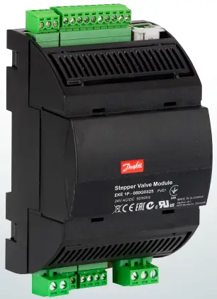
Identification
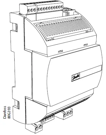
Dimensions [mm]

Application 1

Application 2


Battery back-up

Connection overview: EKE 1P

Valve connection
| CCMT/ETS/CCM | ETS 6 | EKE 1P |
| White | Orange | A1 |
| Black | Yellow | A2 |
| Red | Red | B1 |
| Green | Black | B2 |
Application 1 driver configuration
AI4 open circuit or connected to 0V (COM): high-pressure valve driver
AI4 connected to 5V+: receiver valve driver
Recommended wire size and cable distance between EKE controller and stepper motor valve
| Cable length | 1 – 15 m |
| Wire diameter | 0.52 / 0.33 mm2 (20 / 22 AWG) |
Technical specifications
Power supply:
EKE has galvanic isolation by switch-mode power supply. 24 V AC ± 20 %, 50/60 Hz. Maximum power consumption: 18 VA. Input voltage rating (DC): 24 V DC ± 20%, 15 W.
| I/O | Type | No. | Specification |
| Analogue inputs | Max. 15 V input voltage Do not connect voltage sources to unpowered units without limiting the current to analogue inputs (overall 80 mA). Open circuit HW diagnostics available for voltage input on: AI4 | ||
| Voltage | 2 | AI3* 0 – 5 V ratiometric AI4 0 – 5 V, 0 – 10 V | |
| PT1000 | 2 | AI1*, AI2* | |
| Auxiliary Supplies | 1 | 5 V + Sensor supply: 5 V DC / 15 mA, overload protection approximately 150 mA | |
| Digital inputs | Voltage free contacts |
2 | DI1*, DI2 Steady current minimum 1 mA Cleaning current 100 mA at 15 V DC On: RIL < = 300 Ω Off: RIH > = 3.5 k Ω |
| Digital output |
Relay |
1 | C1-NO1* Normally Open: 3 A General purpose, 250 V AC, 100 k cycle Normally Open: 3 A Inductive (AC-15), 250 V AC, 100 k cycle Normally Closed: 2 A General purpose, 250 V AC, 100 k cycle |
| Stepper motor |
Bipolar / unipolar |
1 | Stepper valves: A1, A2, B1, B2 Bipolar and unipolar stepper motor output:
|
| Battery backup | 1 | VBATT: 18 – 24 V DC (24 V DC recommended):
| |
| Communication | RS-485 RTU | 1 | RS-485* Galvanic isolation No built-in termination |
| CAN | 1 | CAN – RJ Application 1: Connect directly to AK-PC Application 2: Connect directly to graphical display, MMIGRS2. Activate the termination on the graphical display. |
* Only used in application 1
LED indication:
Two sets of Light Emitting Diodes make it possible to follow the operation status of the valve and the controller.

LED A: Two status LEDs indicate power and controller operation
Power-up:

Normal operation:

LED B: Two status LEDs to indicate valve operation

Commonly used parameter identification in application 2
Note: In application 1, the most commonly used parameters are conÿgured in the AK-PC. Default commissioning password: “300”
| Parameter | Default | Description |
| Main switch | 0 | 0 = Off, 1 = ON |
| Mode | 0 | 0=Application 1 – selection by AI4 1=Application 1 – High Pressure expansion module 2=Application 1 – Receiver Expansion module 3=Application 2 – Valve Driver Note: changing this setting also changes the EKE 1P address, causing communication with the graphical display to stop. Communication will resume after a power cycle. |
| AI valve input scale | 2 | 0 = 0 – 5 V |
| 1 = 1 – 5 V | ||
| 2 = 0 – 10 V | ||
| 3 = 2 – 10 V | ||
| 4 = 5 – 0 V | ||
| 5 = 5 – 1 V | ||
| 6 =10 – 0 V | ||
| 7 =10 – 2 V | ||
| 8 = User Defined | ||
| Valve configuration | 0 | Application mode 1: Set from AK-PC except if the valve type is set to User Defined in AK-PC then it is |
| according to below list (see Application mode 2) | ||
| Application mode 2: | ||
| 0 = no valve, 1 = UserDef | ||
| 2 = ETS 12C, 3 = ETS 24C, 4 = ETS 25C, 5 = ETS 50C, 6 = ETS 100C | ||
| 7 = ETS 6, 8 = ETS 12.5, 9 = ETS 25, 10 = ETS 50, 11 = ETS 100 | ||
| 12 = ETS 250, 13 = ETS 400 | ||
| 14 = KVS 2C, 15 = KVS 3C, 16 = KVS 5C | ||
| 17 = KVS 15, 18 = KVS 42 | ||
| 19 = CCMT 0, 20 = CCMT 1 | ||
| 21 = CCMT 2, 22 = CCMT 4, 23 = CCMT 8, 24 = CCMT 16, 25 = CCMT 24 | ||
| 26 = CCMT 30, 27 = CCMT 42 | ||
| 28 = CCM 10, 29 = CCM 20, 30 = CCM 30, 31 = CCM 40 | ||
| 32 = CTR 20 | ||
| 33 = CCMT 3L, 34 = CCMT 5L, 35 = CCMT 8L |
Documents / Resources
 | Danfoss EKE 1P Stepper Valve Extension Module [pdf] Installation Guide EKE 1P Stepper Valve Extension Module, Stepper Valve Extension Module, Extension Module, Module |
 | Danfoss EKE 1P Stepper Valve Extension Module [pdf] User Guide EKE 1P, 80G395, 80G396, EKE 1P Stepper Valve Extension Module, EKE 1P, Stepper Valve Extension Module, Valve Extension Module, Extension Module |
 | Danfoss EKE 1P Stepper Valve Extension Module [pdf] Installation Guide EKE 1P, 080R9344, 80G393, 80G394, 80G395, 80G396, 80G397, 80G398, EKE 1P Stepper Valve Extension Module, EKE 1P, Stepper Valve Extension Module, Valve Extension Module, Extension Module, Module |
 | Danfoss EKE 1P Stepper Valve Extension Module [pdf] Installation Guide EKE 1P, 080R9344, AN31542506734401-000201, EKE 1P Stepper Valve Extension Module, EKE 1P, Stepper Valve Extension Module, Valve Extension Module, Extension Module |


