Danfoss AFPB(-F) 2 Differential Pressure Controller

Specifications
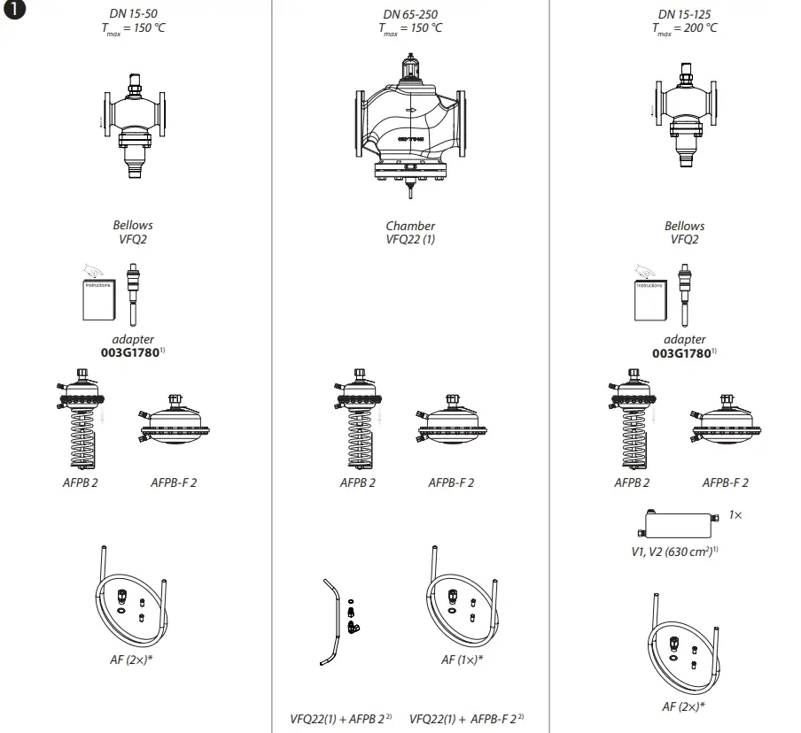
- Model: AFPB(-F) 2 / VFQ 2(1) DN 15-125, VFQ 22(1) DN 65-250
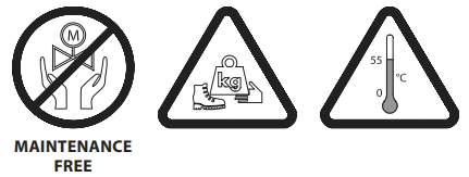
- Maintenance: Free Maintenance
- Pressure Range: PN 16, PN 25, PN 40
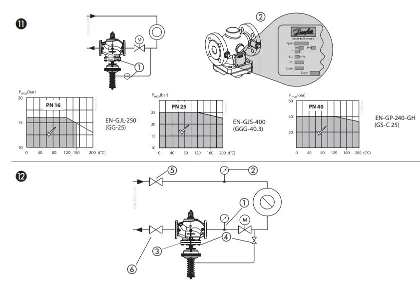
- Materials: EN-GJL-250 (GG-25), EN-GJS-400 (GGG-40.3), EN-GP-240-GH (GS-C 25)
Product Usage Instructions
Facility:
- Prior to assembly, ensure the system is depressurized, cooled down, emptied, and cleaned.
- Follow the specific installation instructions for the AFPB(-F) 2 / VFQ controller.
- Connect the controller as per the provided guidelines.
Maintenance:
- Ensure regular maintenance checks are performed by qualified personnel.
- Follow the maintenance schedule provided in the manual.
Operation:
- Turn the controller as indicated in the manual (~30 turns).
- For direct-connected heating systems, follow the specified instructions for AFPB 2.
- For indirectly connected heating systems, follow the instructions for VFQ 22.
AFPB(-F) 2 / VFQ 2(1) DN 15-125, VFQ 22(1) DN 15-125 www.danfoss.com

AFPB(-F) 2 / VFQ 2(1) DN 15-125, VFQ 22(1) DN 65-250
Assembly Instructions
Safety Notes
![]() Prior to assembly and commissioning, to avoid injury of persons and damages of the devices, it is absolutely necessary to carefully read and observe these instructions.
Prior to assembly and commissioning, to avoid injury of persons and damages of the devices, it is absolutely necessary to carefully read and observe these instructions.
- Necessary assembly, start-up, and maintenance work must be performed only by qualified, trained and authorized personnel.
- Prior to assembly and maintenance work on the controller, the system must be:
- depressurized,
- cooled down,
- emptied and
- cleaned.
- Please comply with the instructions of the system manufacturer or system operator.
Definition of Application
- The controller is used for flow rate limitation and differential pressure control of water and water glycol mixtures for heating, district heating and cooling systems.
- The technical data on the label plates determines the use.
Scope of Delivery ❶
- accessory sold separately,
- Impulse tube set – accessory sold separately
Assembly
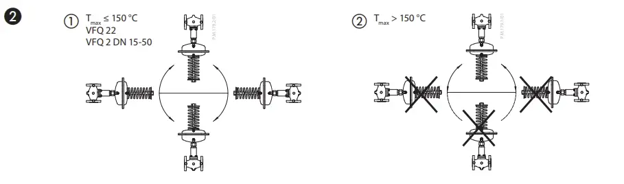
Admissible Installation Positions ❷
- media temperatures up to 150 °C:
Can be installed in any position. - media temperatures > 150 °C. Installation permitted only in horizontal pipelines with the actuator oriented downwards.
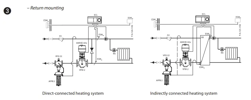
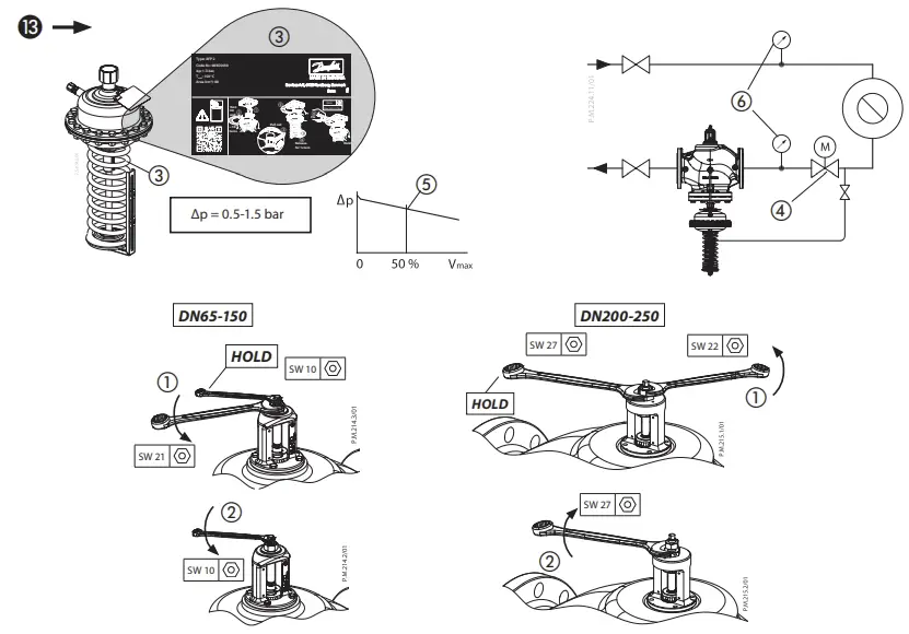
Installation Location and Installation Scheme ❸
- AFPB(-F) 2 / VFQ 22(1) Return mounting ①
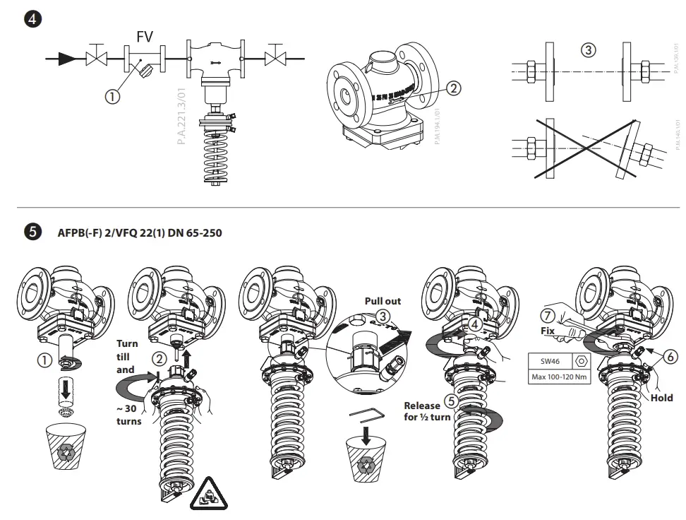
Valve Installation ❹
- Install strainer ① before the controller.
- Rinse the system prior to installing the valve.
- Observe flow direction ② on valve body.
- Install the valve.
- Tighten screws crosswise in 3 steps up to the max. torque.
Flanges ③ in the pipeline must be in parallel position and sealing surfaces must be clean and without any damage.
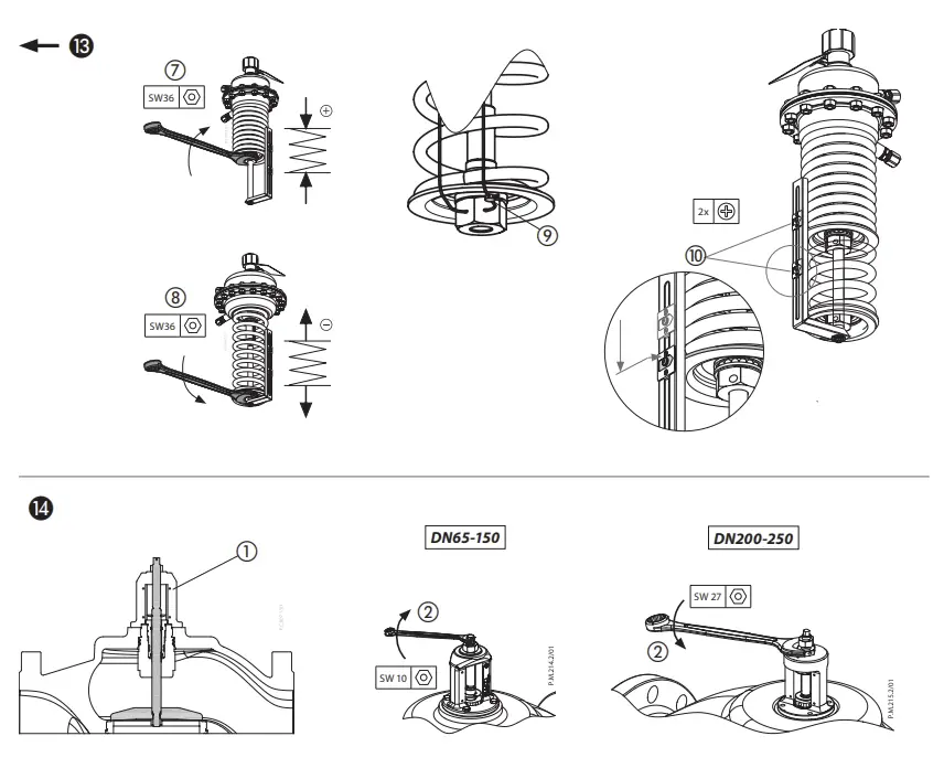
Actuator Installation ❺
The actuator stem must be screwed into the valve stem. Spring on the pressure actuator is factory adjusted (released) for proper installation.
- Remove the spindle protection cup and release the valve spindle by removing the nut, washer and cardboard tube.
- Align the actuator stem with the valve stem, connect both stems and turn gently the whole pressure actuator clockwise with both hands, until the stems are fully connected (valve stem fully screwed into the actuator stem).
- Release the uninon nut by pulling out the blocking spring.
- Tight the union nut
- Release the pressure actuator by turning it counterclockwise for approximately half a turn.
- Observe the position of the impulse tubes’ connection to the valve and align the actuator accordingly.
- Hold the actuator in the position and tight the union nut to the valve with 100- 120 Nm torque.
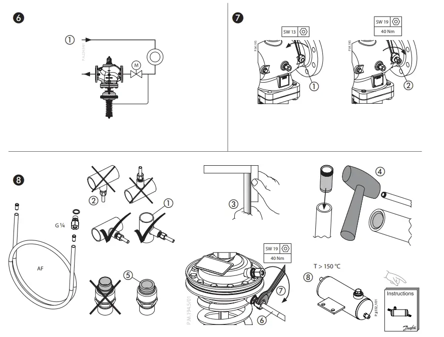
Impulse Tube mounting ❻
Connection of impulse tubes in the system
Overview
- Installation in the return flow ①.
Connection of impulse tube set ❼
Connect the impulse tube set AFPB(-F) to the middle connection.
![]() For instalation of impulse tube sets , please observe the Installation Instructions for the Impulse tube sets.
For instalation of impulse tube sets , please observe the Installation Instructions for the Impulse tube sets.
Connection to the Pipeline ❽
- Which impulse tubes to use?
The impulse tube set AF (2×) ❽ ① can be used: Order No.: 003G1391 or use the following pipes:
| Stainless steel | Ø 10×0.8 | DIN 17458, DIN 2391 |
| Steel | Ø 10×1 | DIN 2391 |
| Copper | Ø 10×1 | DIN 1754 |
No connection downwards/upwards ②, could bring dirt/air into an impulse tube.
- Cut pipe in rectangular sections ③ and deburr.
- For copper pipe: insert sockets ④ on both sides.
- Verify the correct position of the cutting ring ⑤.
- Press impulse tube ⑥ into the threaded joint up to its stop.
- Tighten union nut ⑦ Torque 40
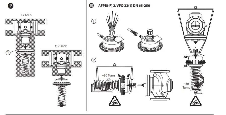
Insulation ❾
For media temperatures up to 120 °C the pressure actuator may be insulated ①.
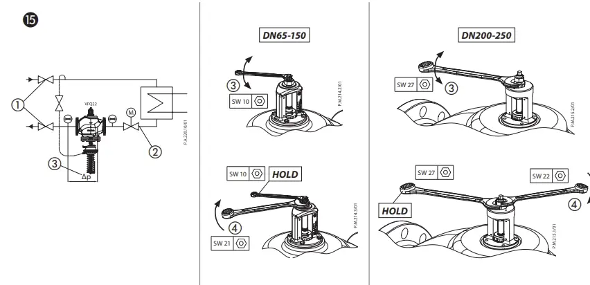
Dismounting ❿
![]() Danger
Danger
Danger of injury by hot water
Prior to dismounting the depressurize system or use shut-off valves on the impulse tubes! ①
Carry out dismounting in following steps: ②
- Fasten pressure actuator with the safety bands to the fixed points in the surroundings
- Before releasing the actuator, fully release the union nut
- Hold the pressure actuator with both hands, and release it by turning it counterclockwise ~30 turns. During turning, control the actuator weight all the time to prevent unexpected fall of the detached actuator.
- Carefully remove the actuator from the valve.
Before installing actuator back to the valve, setting spring must be fully released again.
Leak and Pressure Test ⓫
![]() “Danger of injury by heavy weight of the pressure actuator. When dismounting the pressure actuator from the valve, control the actuator weight all the time to prevent unexpected fall of detached actuator and potential injuries due to the heavy weight!” To prevent damage on the diaphragm, pressure must be constantly and simultaneously increased at the + and − connection ① until the maximum testing pressure is reached.
“Danger of injury by heavy weight of the pressure actuator. When dismounting the pressure actuator from the valve, control the actuator weight all the time to prevent unexpected fall of detached actuator and potential injuries due to the heavy weight!” To prevent damage on the diaphragm, pressure must be constantly and simultaneously increased at the + and − connection ① until the maximum testing pressure is reached.
- In case of higher test pressures, remove impulse tubes at the pipelines ①.
- Observe nominal pressure ② of the valve.
- Max. test pressure must not exceed the plant testing pressure and must always be lower than 1.5 × PN
- Non-compliance may cause damage at the actuator or valve.
- Filling the System, Start-up ⓬
![]() The return flow pressure ① must not exceed the supply flow pressure ②.
The return flow pressure ① must not exceed the supply flow pressure ②.
Non-compliance may cause damage at the controller ③.
- Open shut-off devices ④ that are possibly available at the impulse tubes.
- Slowly open the valves in the system.
- Slowly open shut-off devices ⑤ in the supply flow.
- Slowly open shut-off devices ⑥ in the return flow.
Putting out of Operation
- Slowly close shut-off devices ⑤ in the supply flow.
- Slowly close shut-off devices ⑥ in the return flow.
Set-point Setting
First set the differential pressure.
Differential Pressure Setting ⓭
- Loosen the counter nut ①.
- Unscrew the adjusting throttle ② up to its stop.
- Start system, see section “First Start-up“
- Completely open all shut-off devices in the system.
- Set-point range, see rating plate ③
- Set flow rate on a motorized valve ④ over which the differential pressure is controlled, to about 50 % ⑤
- Adjustment
- Observe pressure indicators ⑥
- Turning to the right ⑦ increases the set-point (stressing the spring)
- Turning to the left ⑧ reduces the set-point (un-stressing the spring)
- The set-point adjuster ⑨ may be sealed.
- Release the not yet used pointer ⑩, move it to the set position and fix it with the screw
Adjustment of Flow Rate Limitation
The flow rate is limited by adjusting the stroke of the adjusting throttle ⓮①.
![]() The system must not be running!
The system must not be running!
When closing the adjusting throttle (step 3), the regulator could be damaged.
- Screw in adjusting throttle ⓮② up to its stop.
- Valve is closed, no flow.
Pre-condition:
Esure that the valves ⓯①② are completely open.
- Observe heat meter indicator
- Turn ③ to increase the flow rate:
- counterclockwise for DN65-150
- clockwise for DN200-250
- Turn ③ to decrease the flow rate:
- clockwise for DN65-150
- counterclockwise for DN200-250
When the adjustment is completed:
- Tighten counter nut ⓯④.
- The adjusting screw may be sealed
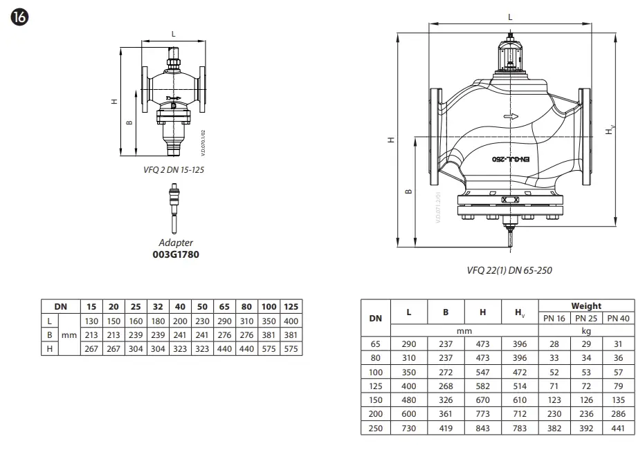
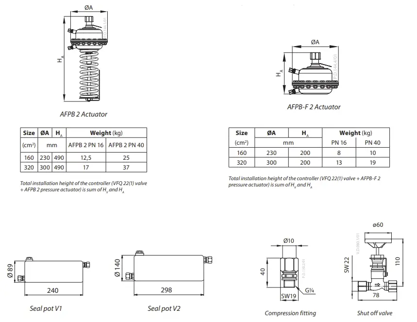
Dimensions, Weights ⓰
Flanges: connection dimensions acc. too DIN 2501, seal form C
FAQs
Q: What safety precautions should I take before assembling and commissioning the product?
A: Prior to assembly, ensure the system is depressurized, cooled down, emptied, and cleaned to avoid injury or damage to devices.
Q: Who should perform the necessary assembly, start-up, and maintenance work?
A: Only qualified, trained, and authorized personnel should carry out assembly, start-up, and maintenance work on the product.
Q: Is the product maintenance-free?
A: Yes, the product is maintenance-free according to the specifications provided.
Documents / Resources
 | Danfoss AFPB(-F) 2 Differential Pressure Controller [pdf] User Guide DN 15-125, DN 65-250, AFPB -F 2 Differential Pressure Controller, AFPB -F 2, Differential Pressure Controller, Pressure Controller |