COMMAND ACCESS TECHNOLOGIES MLRK1 Motorized Latch-Retraction Kit

INSERT INSTRUCTIONS
The Command Access MLRK1 is a field installable motorized latch-retraction kit for:
MRLK1-MRK8 – Marks M8800 Series

Kit Includes
- A. (1) 60728 – MLRK1-MRK8
- B. (1) 51222 – Connecting Bracket
- C. (1) 51048 – Connecting pin
- D. (3) 40067 – E-CLip
- E. (2) 40064 – M4 x 10mm Phillips Flat Head Screw
- F. (1) 40073 – 6-32 x 1/4 Phillips pan head screw
- G. (1) 51263 – MOTOR KIT spacer
- H. (4) 52084 – PAD SPACER
- I. (1) 50030 – 8’ Lead w/ VD Connector
- J. (1) 50944 – MOLex pigtail
SPECIFICATIONS
- Input Voltage: 24VDC +/- 10%
- AVERAGE low Torque LATCH RETRACTION CURRENT: 900 mA
- Average high torque latch retraction current: 2A
- Average holding current: 215 ma
- Wire gauge: Minimum 18 gauge
- Direct wire run – no relays or access control units in-between power supply & module
Optional built-in rex
- SPDT – Rated .5a @24V
- green= Common (C)
- Blue = normally open (NO)
- grey = normally closed (NC)
Recommended Power Supplies: Use a power limited class 2 power supply
All Command Access exit devices & field installable kits have been thoroughly cycle-tested with Command Access power supplies at our factory. If you plan on using a non-command power supply it must be a filtered & regulated linear power supply.
Technical Information

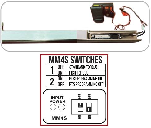
Setting PUSH TO SET (PTS)
Make sure to set PTS before finishing installation
Step 1- Select your preferred torque mode (ships in standard torque) Press the device push pad to the desired setting. (Recommend to fully depress and release 5%, giving the device room for changing door conditions.)
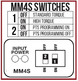
Step 2- While depressing the push pad, apply power. (i.e. presenting the credential to the reader).
Step 3- Continue to keep pad depressed, the device will beep 6 times. After the beeps have stopped,release the pad and now the adjustment is complete. If not to your liking repeat the 3 steps.
Step 4- Once you found the correct location, turn PTS switch to OFF position.
Troubleshooting & Diagnostics
| Beeps | Explanation | Solution |
| 2 Beeps | Over Voltage | > 30V unit will shut down. Check voltage & adjust to 24 V. |
| 3 Beeps | Under Voltage | < 20V unit will shut down. Check voltage & adjust to 24 V. |
| 4 Beeps | Failed Sensor | Verify all 3 sensor wires are installed correctly. Replace sensor if problem persists by contacting office. |
| 5 Beeps | Retraction or dogging failure | After 1st fail: 5 beeps then immediately attempts to retract again. After 2nd fail: 5 beeps with pause in-between for 30 seconds then device attempts to retract again. After 3rd fail: 5 beeps every 7 minutes, device will not attempt to retract. To Reset: Depress bar for 5 seconds at any time. |
| 6 Beeps | PUSH TO SET | Device is recording it’s new position and power mode after the 6th beep. |
Installation Instructions
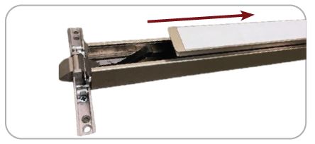
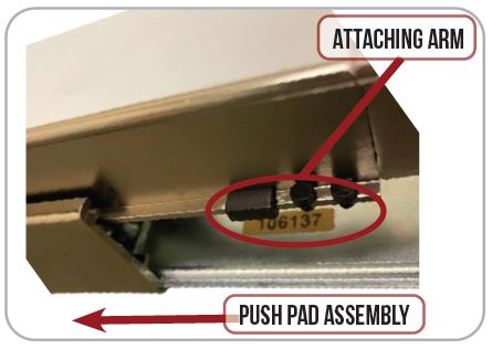
- Slide off push pad assembly from exit device.
- Remove Dogging Assembly if present & install (G) Spacer over existing holes.
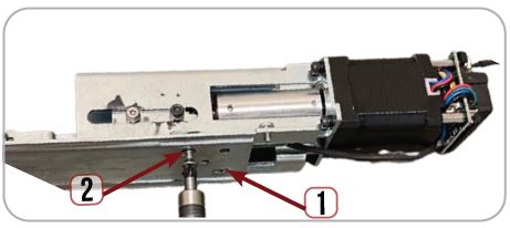
- Line up Mounting Holes on Motor Kit with screw holes on Spacer/Base Rail.
- Turn full assembly to the side & install (E) Screws from underneath to secure motor kit to Base Rail.
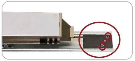
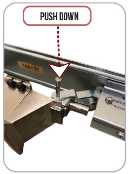
- Slide the (B) Connecting Bracket over the Dogging post at the end of the push pad. Next, move Attaching Arms on motor kit up to line up with holes on B Bracket.
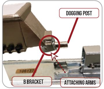
- Once Attaching Arms are lined up insert (C) PIN to connect to (B) bracket.
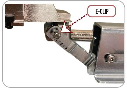
- Install the (D) E-CLIP over the end of the link pin to secure.
- Swap the existing spacers with the (H) PAD SPACER on both sides of push pad next to rubber bumpers to connect to (B) bracket.
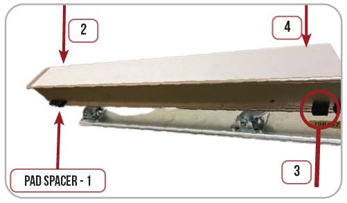
- Re-install the Push Pad Assembly into the exit device housing, keeping an eye on the push pad spacer & rubber bumpers.
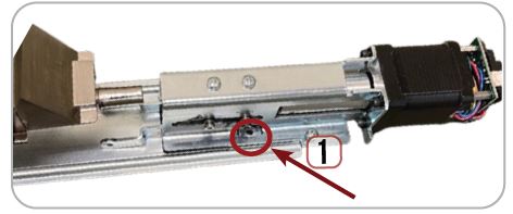
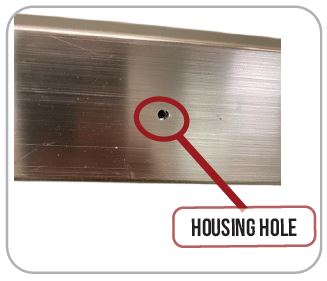
- Locate the hole on the underside of the device and line up the hole with the tapped hole in the base rail.
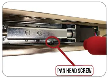
- Locate and install the position set screw (F) Pan Head Screw, to secure push pad assembly to housing.
- Set the “Push to Set Adjustment” following the steps on page 2.
U.S. Customer Support
1-888-622-2377
Visit our website for more details www.commandaccess.com
Canada Customer Support
1-855-823-3002
Documents / Resources
 | COMMAND ACCESS TECHNOLOGIES MLRK1 Motorized Latch-Retraction Kit [pdf] Instruction Manual MLRK1, MRK8, MLRK1 Motorized Latch-Retraction Kit, MLRK1, Motorized Latch-Retraction Kit, Latch-Retraction Kit |
 | COMMAND ACCESS TECHNOLOGIES MLRK1 Motorized Latch Retraction Kit [pdf] Instruction Manual MLRK1 Motorized Latch Retraction Kit, MLRK1, MLRK1 Latch Retraction Kit, Motorized Latch Retraction Kit, Latch Retraction Kit, Motorized Retraction Kit, Retraction Kit |


