![]() Computer smart
Computer smart
REACTIVE ENERGY REGULATOR Computer smart

This manual is intended as a rapid guide to the use and operation of the Computer smart regulator. For further information, you can download the full manual from the Circutor web site:www.circutor.es Any manipulation or use of the equipment different from that specified by the manufacturer may compromise user safety. The apparatus must be disconnected from the power supply before carrying out any maintenance operation. In the event of a failure in the operation or the protections, the unit must be left out of service and its reconnection must be prevented until the problem has been corrected.
Principal functions
– Cos φ regulator → Capacitor connection (6 or 12 steps)
– Network analyzer → Measurement of electrical parameters
– Alarm manager →Display and automatic solution
Connections
A current transformer must be installed for the start-up (In / 5 A) depending on the total current of the load.
The regulator power supply voltage will be two-phase, preferably L1 for UL1 and L2 for UL2 , and the current will preferably be taken from L1. It must be supplied by means of an automatic switch. See cable section and protections in the table of technical features.
The current transformer must be placed in such a way that it measures the total current of the loads plus the capacitors.
The transformer for the leakage current must be placed so that it measures the current in the capacitor bank and must include lines L1, L2, L3, and N. The unit has a switched relay exclusively for the alarm outlet.
Communications
The Computer smart regulators can be connected to a computer or another unit by means of the standard RS-485 bus included. This system is able to focus data on a single registry point (Power Studio® System). In a network of equipment, the Computer smart communicates by question-answer (slave).
The Computer smart communicates with the MODBUS RTU© protocol, which enables it to access the electrical parameter and the main variables and configurations. Contact the manufacturer for the table of addresses.
See section 4.3. to change the configuration of the communication.

Technical features
| Main power supply and voltage measurement. | 480, 400, 230, or 110 Vac. +15 % -10 %; 50 / 60 Hz, (see label) Power supply: Um- Liu. Measurement UL1, UL2, UL3y UN |
| Power supply cables | Section 1.5 mm2 , til 0.5 to 2 A protection fuse |
| Current measurement circuit | Current transformer, In /5 A AC., preferably on phase L1. Min. cable section. 2.5 mm2 |
| Leakage current measurement circuit | Nominal secondary transf. current: lAsec = 2 mA AC. Transformer with ratio of 500: IA = 1 A AC. +20% |
| Current measurement margin | Current I: 0.05 to 5 A AC. (maximum overload +20 %) Leakage current IA: 0.01…1 A AC. (maximum overload +20 %) |
| Measurement accuracy | Voltage and current: 1 %; cos yo. 2 % ± 1 digit |
| Temperature measurement | Approx. external temperature. Range: 0…80 °C. Accuracy: ± 3 °C |
| Consumption | 8.2 VA (empty) ; 9.3 VA (6 relays); 11 VA (12 relays) |
| Output | Relays. Contacts for Umax. 250 Vac., 4 A AC., AC1. |
| Cabling and output relay protection | Cable section 1.5 mm2 , protection with circuit breaker (C curve) of 6 A or gl 6 A fuse |
| Alarm relay | Switched relay for use exclusively for the alarms |
| Standards | IEC 62053-23 (2003-01) Ed. 1.0 IEC 61326-1, EN61010-1 UL 508 |
| Safety /Insulation | Category III, Class II , according to EN 61010-1 |
| Protection degree | IP40 (equipment mounted, cabinet front panel) IP30 (equipment not mounted) according to EN-60529 |
| Admissible environmental conditions | Temperature: -20…+60 °C; Relative humidity: max. 95 % (without condensation). Max. altitude: 2000 m |
| Control system | FCP (a program that minimizes the number of operations) |
| Communications | Interface: RS-485. Protocol MODBUS. Speed: 9600, 19200, 38400 |
| The Computer smart regulator measures and operates in 4 quadrants according to the attached diagram. | 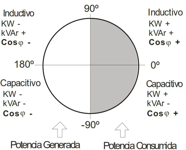 |
Handling and configuration
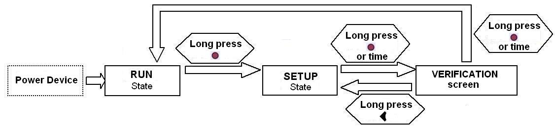
RUN
When it is in RUN, the equipment compensates the reactive energy by connecting the necessary capacitors. In this mode, the display can show different parameters of the installation, depending on the screen.
By pressing the ![]() and
and ![]() arrows, we will move through the different measurement screens.
arrows, we will move through the different measurement screens.
By pressing ![]() the arrow, the maximum values are shown, and by pressing the
the arrow, the maximum values are shown, and by pressing the![]() minimum values are shown of the variables shown on each screen. If you want to see the instantaneous values again, press the key or wait 5 seconds for this to happen automatically.
minimum values are shown of the variables shown on each screen. If you want to see the instantaneous values again, press the key or wait 5 seconds for this to happen automatically.
In the maximum or minimum screen, these can be reset by holding down for![]() the maximums and
the maximums and![]() for the minimums. If you hold down
for the minimums. If you hold down ![]() and
and![]() in the max or min screen, they will all be reset.
in the max or min screen, they will all be reset.
| Measuring screens | Variables shown | Units. | Max. I Min. | |
| Default screen | Cosine and type of cosine U III | V A | xxx | xxx |
| Powers Ill | Active power Ill Reactive power Ill Apparent power Ill | kW kvar kVA | xxx | xxx |
| Phase-neutral voltages | U1, U2, U3 Frequency | V Hz | X X | X X |
| Phase-phase voltages | U12, U23, U31 Frequency | V Hz | X X | X X |
| Currents | Temperature (**) | A mA °C | xxx | xxx |
| Cos/PF | Cosine and type of cosine Power factor | X X | X X | |
| THD’s | THDU THD/ | % % | X X | |
| Voltage harmonics | U odd harmonics from 3 to 13 | % | X | |
| Current harmonics | / odd harmonics from 3 to 13 | % | X | |
| Number of connections (*) | No. of connection of each capacitor | X10 | ||
(*) They are reset by pressing and holding down the key.
(**) An approximation of the external temperature of the equipment by an internal sensor.
Error and alarm codes
In the measuring screens, there may be a different error or alarm codes making the screen backlight flash. The meaning of each of the codes is summed up in the following table:
| ERROR message | Description |
 | No current. Load current below the minimum or current transformer not connected. It appears if the secondary current < 50 mA. |
 | On compensation. The unit measures capacitative power and all steps are disconnected. |
 | Sub-compensation. The unit measures inductive power and all steps are disconnected. |
 | Over-current. The measured current exceeds the nominal current by +20 %. The nominal current is considered to be that of the primary of the TC. |
 | Overvoltage The measured voltage exceeds the nominal voltage by +15 %. |
 | Low voltage. The voltage in some of the phases is under 90% of the nominal. |
 | THD alarmU. The THDU levels are higher than those configured in the THDU alarm. |
 | THD alarm/. The THD/ levels are higher than those configured in the THD! alarm. |
 | Leakage Alarm. The leakage current is higher than that configured in the leakage current alarm. |
 | Cosine Alarm p. The p cosine is out of the range configured in the Cosine alarm cp. |
 | Temperature Alarm. The measured temperature is higher than that configured in the Temperature alarm. |
 | Repeated Leakage Alarm. Leakage has been detected in the system, but the cause has not been found. |
 | Leakage Alarm in Capacitors. Leakage has been detected that is caused by one of the capacitors and this capacitor is disabled. The disabled capacitors are shown flashing. To enable them once more, see the Leakage Alarm configuration in section 4.4. |
 | Leakage current transformer not connected alarm (if the leakage alarm is _ enabled). |
AUTO-TEST
The equipment allows a self-test to be made for the maintenance of the capacitors, by connecting them individually and measuring connected power and leakage current. To perform the self-test, the unit must be in the SETUP screens ![]() and
and![]() must be pressed for a few seconds at the same time. In the AUTO-TEST screen, the
must be pressed for a few seconds at the same time. In the AUTO-TEST screen, the![]() and
and ![]() keys show the data of each capacitor. To start the process, press and hold down
keys show the data of each capacitor. To start the process, press and hold down![]() . The load must be stable during the process. To leave SETUP, press
. The load must be stable during the process. To leave SETUP, press ![]() and
and![]() for a few seconds together, or press and hold down
for a few seconds together, or press and hold down to go to the checking screen. Further information on the AUTOTEST in manual.
SETUP
In SETUP the ![]() and
and![]() keys are used to move through the different screens and see the configurable parameters of the equipment.
keys are used to move through the different screens and see the configurable parameters of the equipment.
To edit some parameters, press the key to enter edition mode and the parameter to be edited will flash. Then the ![]() or
or![]() keys will be used to increase or decrease the value, and the
keys will be used to increase or decrease the value, and the![]() or
or![]() keys to change the editable parameter. Once the screen parameters have been configured, press to confirm and leave the edition mode.
keys to change the editable parameter. Once the screen parameters have been configured, press to confirm and leave the edition mode.
P&P (PLUG AND PLAY): To start the process, press and hold down![]() . The P&P automatically adjusts the PHASE, C/K, PROG and STEPS parameters in a step connection process. After the measured cosine (confirmation of the chosen PHASE) and the configuration made. For correct operation, the load must be inductive, with cos phi > 0.5 and stable (variation < 10%). If the program is not standard, the P&P starts with
. The P&P automatically adjusts the PHASE, C/K, PROG and STEPS parameters in a step connection process. After the measured cosine (confirmation of the chosen PHASE) and the configuration made. For correct operation, the load must be inductive, with cos phi > 0.5 and stable (variation < 10%). If the program is not standard, the P&P starts with![]() (long). After the P&P, the primary of the TC has to be configured (IP screen) for the equipment to measure the current and the powers correctly. Further information on Plug&Play in manual.
(long). After the P&P, the primary of the TC has to be configured (IP screen) for the equipment to measure the current and the powers correctly. Further information on Plug&Play in manual.
IP: The current of the installed transformer primary is configured bearing in mind that the current secondary is always 5 A. Range of values between 5 and 9999.
COS: Configuration of cosine phi to be reached and its type (inductive or capacitive
 ). Range of values between 0.70 and 1.00.
PHASE: Phase configuration depending on how the current transformer has been connected. The cosine phi is also shown to check the correct phase, it is understood that in a normal installation, it must be between 0.60 and 0.99 caps.
| Display | Ph1 | Ph2 | Ph3 | Ph4 | Ph5 | Ph6 |
| TC connection | L1 | L2 | L3 | L1 (TC inverted | L2 (TC inverted) | L3 (TC inverted) |
C/K: Configuration of the ratio between the current of the first phase and the current transformer. Range of values between 0.02 and 1.00. Table for a network voltage of 400 V.
| TC | Power in kvar of the first step at 440 V | |||||||||||||
| I | 3. | 5 | 6. | 8. | 10 | 13. | 15 | 20 | 25 | 30 | 50 | 60 | 75 | 100 |
| 7515 | 0,20 | 0,40 | 0,60 | 0,80 | 0,99 | |||||||||
| 100/5 | 0,15 | 0,30 | 0,45 | 0,60 | 0,75 | 0,89 | ||||||||
| 15015 | 0,10 | 0,20 | 0,30 | 0,40 | 0,50 | 0,60 | 0,80 | 0,99 | ||||||
| 200/5 | 0,07 | 0,15 | 0,22 | 0,30 | 0,37 | 0,45 | 0,60 | 0,75 | 0,89 | |||||
| 25015 | 0,06 | 0,12 | 0,18 | 0,24 | 0,30 | 0,36 | 0,48 | 0,60 | 0,72 | 0,95 | ||||
| 30015 | 0,05 | 0,10 | 0,15 | 0,20 | 0,25 | 0,30 | 0,40 | 0,50 | 0,60 | 0,80 | 0,99 | |||
| 40015 | 0,07 | 0,11 | 0,15 | 0,19 | 0,22 | 0,30 | 0,37 | 0,45 | 0,60 | 0,75 | 0,89 | |||
| 50015 | 0,06 | 0,09 | 0,12 | 0,15 | 0,18 | 0,24 | 0,30 | 0,36 | 0,48 | 0,60 | 0,72 | 0,89 | 0,95 | |
| 60015 | 0,05 | 0,07 | 0,10 | 0,12 | 0,15 | 0,20 | 0,25 | 0,30 | 0,40 | 0,50 | 0,60 | 0,75 | 0,80 | |
| 800/5 | 0,06 | 0,07 | 0,09 | 0,11 | 0,15 | 0,19 | 0,22 | 0,30 | 0,37 | 0,45 | 0,56 | 0,60 | ||
| 1000/5 | 0,04 | 0,06 | 0,07 | 0,09 | 0,12 | 0,15 | 0,18 | 0,24 | 0,30 | 0,36 | 0,45 | 0,48 | ||
| 1500/5 | 0,04 | 0,05 | 0,06 | 0,08 | 0,10 | 0,12 | 0,16 | 0,20 | 0,24 | 0,30 | 0,32 | |||
| 2000/5 | 0,04 | 0,06 | 0,07 | 0,09 | 0,12 | 0,15 | 0,18 | 0,22 | 0,24 | |||||
| 2500/5 | 0,05 | 0,06 | 0,07 | 0,10 | 0,12 | 0,14 | 0,18 | 0,19 | ||||||
| 3000/5 | 0,04 | 0,05 | 0,06 | 0,08 | 0,10 | 0,12 | 0,15 | 0,16 | ||||||
| 4000/5 | 0,04 | 0,06 | 0,07 | 0,09 | 0,11 | 0,12 | ||||||||
For network voltages other than 400 V, the result of the table must be multiplied by Network /400. C/K can be calculated with the following expressions:
Example calculation of C/K : TC ratio = 500/5 ; 1st capacitor: 60 kvar , 440 Vac. PROG: This configuration depends on the ratio of Hvar between the different steps with respect to the first. For example, 10+20+20+20 kvar would be program 1222. If it is not a standard programme, choose OPEn and configure any program between 1111 and 1999.
STEPS: Configuration of the number of steps of the battery.
DELAY: Configuration of the connection time between steps (seconds). Range of values from 4 to 999 s. The reclosing system time is 5 times the DELAY.
COMM: Baud Rate (9600 – 19200 – 38400), parity (none-odd-even), number of stop bits (1 or 2), and number of peripherals (1-255).
ALARM: alarm enabling (on-off) and the possibility of their triggering the alarm relay (yesno). With the ![]() and
and![]() keys, the different arms are displayed.
keys, the different arms are displayed.
ALARM COS: The cosine limit value and type (inductive or capacitive ) under which the alarm would be triggered (E10) are configured. A minimum value is also configured for the current needed to make the cosine alarm come on. ALARM THD: The alarm limit values are configured as a % above which the THDU and/or THDI (E07 and E08) would be triggered. A step must be connected for a THD alarm to be triggered.
ALARM ILEAK: The alarm limit value is configured in mA above which the leakage current would be triggered (E09). The option to search for faulty capacitors when E09 (Off-On) has been triggered is also configured. If there are capacitors annulled by this alarm, the reset option appears (yes-no).
ALARM TEMP: Limit value for the temperature alarm (E11) in ºC.
On/Off/Auto: The state of the battery capacitors is configured (On: Always connected, Off always disconnected, and Auto: the regulator decides when to turn it on or off). With the![]() and
and ![]() keys, the different capacitors are displayed.
keys, the different capacitors are displayed.
DISPLAY: The luminosity of the backlight is configured as a percentage, as well as its state (On: always alight, Off: always out, Auto: it goes out after 5 minutes if no key is pressed).Circular S.A. Vial Sant Jordi, s/n 08232 Viladecavalls Tel. – 93 745 29 00 Fax – 93 745 29 14 E-mail : central@circutor.es
Technical service In the event of any query on operation or fault, consult the equipment manual, www.circutor.es or call the technical service: email: sat@circutor.es Spain: 902 449 459 International: (+34) 93 745 29 00
Documents / Resources
 | Circutor M98235801 Reactive Energy Regulator Computer Smart [pdf] Instructions M98235801, Reactive Energy Regulator Computer Smart |


