![]() 1500 Series III Intercom Systems
1500 Series III Intercom Systems
Installer’s Reference Guide
For Firmware Versions 5.01 – 5.03
1500 Series Intercom Systems
Including new phase 2 models:
- 1500B
- 1500BH
- 1502B
- 1503B
- 1503BW
- 1509B
- 1509BV
- 1520B
- 1522B
- 1515B
- 1516B
WARNINGS
- Read these instructions before installing or using this product
- To reduce the risk of fire or electric shock, do not expose components to rain or moisture.
- This product must be installed by qualified personnel.
- Do not expose this unit to excessive heat.
- Clean the unit only with a dry or slightly dampened soft cloth
LIABILITY STATEMENT
Every effort has been made to ensure that this product is free of defects Audio Authority® cannot be held liable for the use of this hardware or any direct or indirect consequential damages arising from its use It is the responsibility of the user of the hardware to check that it is suitable for his/her requirements and that it is installed correctly All rights are reserved No parts of this manual may be reproduced or transmitted by any form or means electronic or mechanical, including photocopying, recording or by any information storage or retrieval system without the written consent of the publisher
Audio Authority® reserves the right to revise any of its hardware and software following its policy to modify and/or improve its products where necessary or desirable
Audio Authority and the Double-A Symbol are registered trademarks of Audio Authority Corp. Copyright April, 2023. All third party trademarks and copyrights are recognized
See www.audioauthority.com/page/service_policy for full warranty disclosure
1500™ Series III Intercom Systems
Series 1500 Intercom systems enable clear two-way communications in retail service businesses Two-way video can be integrated with high-performance audio to provide a complete intercommunication solution over a single Category 5/6/7 UTP cable The versatile Model 1500B counter station can access up to 12 lanes Lane stations can be connected directly to a counter station in a one-on-one system, or multiple counter stations and lane stations can be networked using an Audio Authority intercom hub.
Model 1509B and 1509BV mini hubs are perfect for two-on-four intercom systems, while A-V system hubs can support up to eight counter stations on 12 lanes Video communication is easily added by installing a Model 1502 two-way video display for counter stations Video in the lane can be installed using separate cameras and displays, or Audio Authority video customer stations.
Series III compatibility with legacy 1500 systems:
The 1500B and other Series III components are designed to work with recent legacy systems and components, however, certain features may not be compatible. When B version is mentioned, assume the A version is also compatible unless noted.
Learn more here: www.audioauthority.com/page/intercom_faq
Special Tools & Supplies
- Cat 5 network cable tester
- RJ-45 plug crimping tool (Audio Authority recommends EZ-RJ Pro crimp tool)
- Category 5e or 6 UTP cable and RJ-45 terminations (Audio Authority recommends EZ-RJ-45 connectors)
- 18mm flare nut wrench for gooseneck mic installation
- Model 1550A Installer Setup Display
System Components
(Including Series III (bold)
| Counter station (audio) | 1500B | Integrated A-V customer station | 1527AVB |
| Counter station with Handset | 1500BH | A-V video display with camera | 1527VB |
| Counter station video monitor | 1502B | Surface-mount customer handset | 1540 |
| Handset cradle | 1503B | Flush-mount customer handset | 1541 |
| Handset cradle wall mounted | 1503BW | Wireless headset (Sennheiser) | 1542S |
| 2-on-4 audio only hub | 1509B | Traffic sensor | 1547B |
| 2-on-4 audio-video hub | 1509BV | Installer setup tool (LCD) | 1550A |
| 4-on-4 audio-video hub | 1510A* | Adjustable mounting arm | 1594 |
| 4-on-8 audio-video hub | 1511A* | Universal power supply 1.5A | 571-043 |
| 8-on-12 audio-video hub | 1512A* | Heavy duty power supply 5A | 571-053 |
| 4-counter plug-in card | 1515B | Gooseneck microphone | 631-026 |
| 4-lane plug-in card | 1516B | External microphone kit | 631-029 |
| System plug-in card | 1517A | External 3” speaker | 631-030 |
| Lane station | 1520B | Water Resistant Microphone | 631-055 |
| Dual lane station | 1522B |
*See page 15 and 16 for hub configurations
1-on-1 Audio or A-V Installation
The simplest system configuration involves only one counter station connected directly to one lane station (no hub).
This configuration can be audio-only or audio-video. Run a length of Cat 5 cable from the counter location to the lane location. Separate camera and monitor may be installed and connected to a 1520B, or the 1527AVB may be connected, which includes those peripherals in the enclosure See page 11 for detailed instructions.
Note: In systems without a hub, the only way to upgrade firmware is to temporarily connect a hub in the system and a 1550A to the counter station while performing these operations.
1-on-2 Audio Installation
The dual lane audio configuration involves only one audio counter station serving two lanes (no hub). This configuration is audio-only Run a length of Cat 6 cable from the counter location to the dual lane station The 1522B may be located inside near the counter station or outside in a sheltered location such as up in the canopy over the lanes When running wiring to lane devices be sure to protect individual wires or use an approved multi-conductor cable.
Note: In systems without a hub, the only way to upgrade firmware is to temporarily connect a hub in the system and a 1550A to the counter station while performing these operations.
2-on-4 Audio Installation (Audio Mini Hub)
The Model 1509B audio mini hub allows one or two Model 1500B counter stations to serve up to four 1520B lane stations Run a length of Cat 5 cable from each counter station to the Hub Run a length of Cat 5 cable from the Hub to each lane station Mini hubs now allow for custom key assignments via the1550A installer setup tool (see page 18).
2-on-4 Video and Audio Installation (Video Mini Hub)
The Model 1509BV A-V mini hub allows one or two Model 1500B counter stations to serve up to four 1520B lane stations Run a length of Cat 5 cable from each counter station to the Hub Run a length of Cat 5 cable from the Hub to each lane station Mini hubs now allow for custom key assignments via the1550 installer setup tool For separate camera and monitor, connect via BNC ports on 1520B. 
Wiring
Series 1500 is designed for excellent performance using Cat 5 cable (Cat 5e / 6 / 7 is Unshielded Twisted Pair cable that carries multiple signals for long distances). Follow instructions below, or in retrofit installations where the existing wiring must be used, refer to 1500 alternate wiring instructions (752-502) at www.audioauthority.com.
Cat 5 Cable Fabrication
Terminate the ends of each Cat 5e/6 cable with RJ-45 modular plugs using the EIA 568B pinout (paired 1-2, 3-6, 4-5, and 7-8). Premade network cables may also be used for shorter runs TEST all cables (including pre-made) with a network cable tester.
Installing 1500B Counter Stations
- Unpack each Model 1500B counter station and, if applicable, install a 1502B video display. Plug the Cat 5 video cable into the matching port on the 1500B.
- Attach the field-replaceable microphone, tightening the nut securely with a 18mm flare nut wrench, and tuck its rubber boot firmly into place.
- Plug the Cat 5 cable from the hub into the hub port of each 1500B and connect the power supply to the Power jack
- Pry up the keypad cover and install the desired key colors in the Model 1500B. On initial power-up, the hub sets the default key layout automatically according to the number of connected Counter and lane stations (see examples below). You can choose to color-code by the carrier color or label the keys numerically Place blank, black chips in all non-active positions. Store the unused key chips on the premises for future changes or expansion.


Installing 1502B Video Monitor
1500 Series customer stations can be augmented with 2-way video capability All video monitors are installed in the field. The 1502B is compatible with 1500A and 1500B.
Mounting
- First connect the cable to the video port on the counter station
- Install rear mounting screws but do not fully tighten until the third screw is installed on the bottom (next).
- 1502B has a third mounting screw on the bottom It is only used with 1500B counter stations Use only the short screw provided with the 1502B – a longer screw will cause damage.

Digital Camera Tilt
The indoor camera view can be adjusted up or down digitally This controls what the customer sees in the lane Press the Mirror key, then Camera Up/Down.
Monitor Tilt Control
The monitor tilt can be hand adjusted If the monitor does not hold position, use a hex wrench to tighten the mount as shown.
Monitor Height Position
The monitor height can be set to the low position by removing the four screws on the rear of the monitor and moving the bracket. If a set screw is present, do not remove it when changing the monitor height as shown.
Installing Model 1503B
1500B counter stations may be fitted with a handset cradle on location. Install the counter station as above, but connect the included handset to the handset port on the underside of the counter station as shown Adjust handset volume using the 1550A Installer setup tool, then, if more adjustment is desired, use the two recessed knobs marked TX and RX on the top of the 1503B cradle. Wall mounted cradle (1503BW) is similar, see detailed instructions in box.
Installing Model 1520B Lane Stations
Lane stations may be placed at the customer end of a drive-up or walk-up intercom system The Model 1520B is the basic lane station unit for installations where the microphone, speaker (plus video screen and camera, if used) are mounted separately The Model 1527AVB video lane station incorporates all of the features of the 1520 plus a microphone, speaker, camera and video screen mounted inside its enclosure. The Model 1527VB 2-way video monitor must be used with a 1520B, and is equipped with a camera and video screen, but no audio. Connect with Cat 5/6 cable, 20 ft or less.
- Install the Model 1520B lane station in each deal drawer or pneumatic unit, using the screws provided. If AC power is not available at the customer end, see Step 5.
- Install the lane mic and speaker Mount the speakers in the grilles provided in the drive-up units The 631-055 water resistant microphone mounts in a 3/4 inch hole (19mm) drilled in the face of the drive-up cabinet At each lane, place the microphone and speaker as far apart as practical, while placing the microphone to receive customer speech. Insert the microphone and tighten the nut, then connect the cable. Install teller call button if needed.
- Connect the mic*, speaker and teller call switch to the 1520B terminal block. Strip all wires 1/4” long If pneumatic blower muting is desired, connect the DRY blower contacts to the corresponding points on the terminal block, using small (22-18 AWG) wire. If traffic sensors or remote-controlled security doors are in use, connect them as indicated.
- At each lane where video is in use, connect 75-ohm NTSC cameras and monitors to the 1520B video jacks, or connect a Model 1527VB customer video display to the Video port on the 1520B Connect power supplies.
- Plug the lane power supplies into a source of 100-240 volts AC If AC power is not available on the customer end, a power supply may be located indoors and its output leads extended using a suitable gauge of wire as shown. To power multiple lane units from a single power supply source, contact Audio Authority Technical Support.
| Recommended AWG For Power Supply Leads | |
| Maximum Distance | Gauge |
| 40 ft | 18 |
| 60 ft | 16 |
| 100 ft | 14 |

Installing Model 1522B Dual Lane Stations
- Install the Model 1522B lane station in the deal drawer, under the counter, in a drive-up cabinet, or inside a dry location in the canopy using the screws provided. If AC power is not available at the mounting location, see Step 4.
- Install the lane mic and speaker Mount the speakers in the grilles provided in the drive-up units The 631-055 water resistant microphone mounts in a 3/4 inch hole (19mm) drilled in the face of the drive-up cabinet At each lane, place the microphone and speaker as far apart as practical, while placing the microphone to receive customer speech. Insert the microphone and tighten the nut, then connect the cable. Install teller call button if needed.
- Use a separately shielded conductor to connect the microphone to the Model 1522B Dual Lane Station if extending beyond 6 ft Strip all wires 1/4” long. If pneumatic blower muting is desired, connect the DRY blower contacts to the corresponding points on the terminal block, using small (22-18 AWG) wire. If traffic sensors or remote-controlled security doors are in use, connect them as indicated.
- Plug the 1522B power supply into a source of 100-240 volts AC. If AC power is not available, plug in a power supply indoors and extend its output leads using a suitable gauge of wire as listed.

1520B and 1522B Wiring Notes
- If extending microphone beyond 6 feet, use separately shielded cable to maintain audio quality.
- Connect the lane station Common terminal (of one lane) to a reliable ground.
- Connect the Drain Wire to the lane station Common terminal, and trim at the other end.
- N O (Normally Open) Contacts are used for any device such as a door latch or solenoid that must be operated from the counter station.
Operation
The Series 1500 Intercom is operated via touch-sensitive.
keys on Model 1500B counter station keypads, shown below. Tasks such as answering a customer call, ending a call, and putting a customer on hold are shown on the Operator Guide (page 14) which should be kept near the counter station for reference.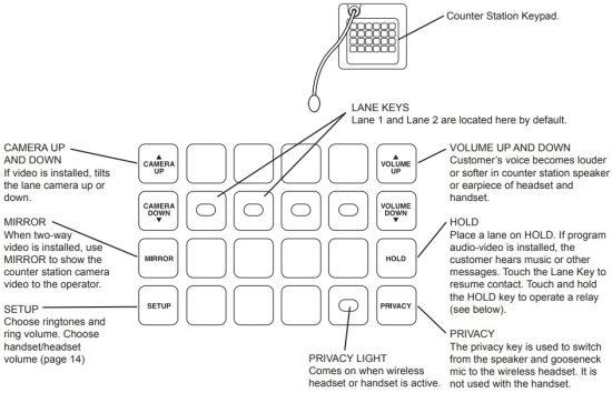 Operating Remote Devices
The 1520 can be wired to operate a latch or door in a remote location via the 1500B keypad (see page 10 for relay connection details) The system can be set up (using the 1550A) to be operated in two different ways; consult your technical support provider for details.
- Option 1: Any time the lane is selected the remote device is active (e g a door opens)
- Option 2: When a lane is active, the operator touches and holds the HOLD key to activate the device (e.g. hold the door open). The HOLD key operates normally when touched briefly.
Using a Wireless Headset or Handset
The 1500B switches between the built-in speaker and gooseneck microphone, the 1503B handset, and an optional wireless headset. Some examples of using these communication methods are listed below. Always deactivate the wireless headset between customer interactions to increase battery life.
Answering a Call
- Speaker/gooseneck mic: Touch the rapidly flashing lane key.
- Handset: Pick up the handset, touch the rapidly flashing key.
- Wireless headset: Activate the headset, touch PRIVACY and select the flashing lane. If the headset is the preferred method, leave PRIVACY on.
Note:
The only supported headset model is currently the Sennheiser D 10. Others may be compatible, but are not supported.
Putting a Call on HOLD
- Speaker/gooseneck mic: Touch HOLD
- Handset: Touch HOLD, then hang up the handset.
- Wireless headset: Touch HOLD
Picking Up a Call from HOLD
- Speaker/gooseneck mic: Touch the blinking lane key
- Handset: Touch the blinking lane key and pick up the handset
- Wireless headset: If PRIVACY is already on, activate the headset and select the blinking lane key.
Tips
- Speak naturally into the microphone at a distance of about two inches
- Touch keys with the pad of your finger
- Press MIRROR to view yourself (2-way video only) – to aim camera, adjust display tilt
Lane Key Lights
RED (flashing rapidly) = Customer CALLING for service
GREEN = Customer in 2-WAY contact with your counter station
RED = Customer in 2-WAY contact with another counter station
GREEN (blinking slowly) = Customer placed on HOLD from your counter station
RED (blinking slowly) = Customer placed on HOLD from another counter station
GREEN (flashing rapidly) = Monitoring transaction on another counter station (Master Teller)
Counter Station
- To contact a customer calling Touch LANE key
- To place a customer on HOLD Touch the HOLD key
- To contact a customer on hold Touch the LANE key
- To end contact with customer Touch the active LANE key
- To cancel hold and end contact Touch the LANE key twice
- To talk over a customer Touch and hold the active LANE key
- To adjust incoming volume Touch VOLUME UP or VOLUME DOWN key
- To enter/exit PRIVACY (headset) mode Touch the PRIVACY key
- To activate remote relay See installer or administrator for instructions
Adjust Counter Station Handset Volume (1500BH or 1503B) or Headset Volume (e.g. 1542S)
- In SETUP MODE, touch PRIVACY and press VOLUME UP or DOWN
- If further volume adjustment is needed (handset transmit or receive) contact your tech support provider
Wireless Headset
- To use a wireless headset, touch PRIVACY, activate the headset, and select the flashing lane key
- If the headset is your preferred method of operation, leave privacy on
- To increase headset battery life, deactivate the headset between customer interactions
Handset
- To answer a call, pick up the handset and touch the rapidly flashing lane key
- To place a customer on hold, touch HOLD
- To speak to a customer on hold, pick up the handset and touch the lane key
Counter Station Video
- To adjust outside camera on selected lane Touch CAMERA UP or CAMERA DOWN key
- To view yourself (to aim camera) Touch MIRROR key (30 second time-out)
- To view outgoing video program Hold MIRROR key 3 seconds (no lane selected)
- To pause lane camera scrolling Touch HOLD key (no lane selected)
- To view next lane camera Touch CAMERA UP key (no lane selected)
- To view previous lane camera Touch CAMERA DOWN key (no lane selected)
Adjust Ringtones and Ringer Volume
- Touch and hold the SETUP key until lights next to CAMERA and VOLUME keys blink
- Touch CAMERA UP and DOWN to select one of 16 ringtones
- Touch VOLUME UP and DOWN to set ringer volume
Installing Mini Hubs
The Model 1509B and BV are mini hubs with a maximum capacity of two counter stations serving four lane stations.
- Install the hub under the counter or other dry, secure location such as a telephone closet or inside a lane cabinet or mezzanine Ground the hub to a nearby electrical outlet cover using the attached green grounding wire.
- Run a length of Cat 5 cable from each counter and lane station to the hub Observe the fabrication guide on page 8, and use a cable tester to verify the terminations.
- Apply hub power last, and adjust volume level during system testing.

Installing the A-V System Hub (1510, 1511, 1512)
- Position and install the hub under the counter or in a secure indoor location such as a telephone closet Ground the hub to a nearby electrical outlet cover using the green grounding wire attached to the hub.
- If the installation requires additional capacity, install a counter card or lane card(s) as needed (see page 16).
- Run a length of Cat 5 cable from each counter and lane station to the hub Observe the cable fabrication guide on page 11, and use a cable tester to verify the terminations.
- Connect other equipment as needed .
See page 11 for more on program audio. - After lanes are connected, apply power to the hub.

A-V System Hub Model 1510
- The Model 1510A is an audio-video hub with a capacity of up to four counter stations serving four lane stations The hub’s capacity can be expanded in the field by adding counter and/or lane cards (see page 16).
- System settings can be stored on a standard SD card for security or replication purposes Firmware upgrades can be downloaded from the Audio Authority website and performed using the SD card when necessary These operations require a Model 1550A installer setup tool and a counter station.
- Composite video and stereo analog audio inputs allow multimedia source devices to play advertising content on any lane whenever customer is on hold or it is idle See page 12 for details.
- Direct outputs from wide angle camera (dedicated security camera) and/or lane cameras for surveillance recording Video is output continuously from each camera connected.

Hub Configurations and Capacity
Shown below is the A-V hub with a maximum capacity configuration. Other pre-installed configurations are available; contact Audio Authority® for details, or visit www.audioauthority.com.
Add Cards to Increase Capacity
To increase counter or lane station capacity, remove power from the hub. Remove the blank faceplate from the appropriate card slot(s) and insert the new cards carefully, making sure the connections are firmly seated. Insert the two screws to secure the card, and connect new lane stations or counter stations. Connect power and test the system. Using Traffic Sensors
Lane stations provide an RJ45 connection for Audio Authority’s Model 1547B traffic sensor. When a vehicle triggers the 1547B, the counter station generates a call tone for the corresponding lane to alert the operator. The call tone for the traffic sensor can be a different ring tone from the call button at the same lane (see page 22). To extend a traffic sensor, use an in-line coupler and a length of Cat 5 cable.
A third party traffic sensor may be used by connecting it to the TRAFFIC SENSE terminal (pin 6) and COMMON terminal (pin 8). Third party sensors have different pinouts and color codes. Be sure to verify the specific pinout with the manufacturer’s documentation.
Using Ringtones
16 different ringtones are available in the 1500 system Operators may choose a distinct ringtone for each counter station and adjust the ringtone volume using console controls (see operator instruction card on page 13) Using the 1550A the installer may assign each lane a distinct ringtone (see ringtone override, page 18), and designate one ringtone for IR traffic sensors, and a different one for call buttons (see menu map, page 22).
Playing Audio and Video Content Through Lane Stations
If audio or video messaging content will be playing when customers are on hold or the lane is idle, plug the source player into the PROGRAM INPUT ports on the 1517A hub card Program audio level may be manually adjusted at the hub Any lane’s program audio may be turned off during idle periods (still heard while on hold) using the 1550A Program Audio Abate setting (see page 18). If the program video source is a PC, either a composite video card or external converter is required to scale the PC video output to standard definition composite video signal. 
Using the 1550A Installer Setup Tool
System Calibration and Setup
The Model 1550A is a display that shows the setup menus and settings for Series 1500 Intercom Systems See page 22 for a menu map and default values The entire system can be calibrated from one counter station.
Connect the CAT 5E/6 cable to the RJ45 jack on the underside of any live counter station (the jack is at an angle) Return the counter station to its upright position and connect the 1550A Setup Tool If the counter station has an attached handset cradle (1500AH or 1503B, etc.) make sure the handset is resting in the cradle before you connect the 1550A.
Basic Setup Procedure
- Hold the SETUP key on the counter station for one second to enter Setup mode The 1550A displays: “SERIES 1500 EQUIPMENT CALIBRATION PLATFORM”.
- To navigate the menus, use the VOLUME UP and VOLUME DOWN keys to move the cursor.
- Touch SETUP to enter a submenu or confirm a selection, and PRIVACY to go back.
- Any changes you make are recorded as you exit each submenu. When you exit Setup mode, you must choose to either save all changes and exit or exit without saving.
Power User Tips
- For faster menu navigation, submenus may be selected by touching a key that is lit RED corresponding to the menu item (see the numbered keys above). For instance, to enter BLOWER MOTOR DELAY, press 1 and then 1.
- See page 22 for a menu map and default values.
- To exit Setup mode from any menu, hold SETUP for one second and follow the prompts on the 1550A.
- After adjusting a lane station or counter station, you can use the CAMERA UP or CAMERA DOWN keys to select other stations for adjustment without leaving the submenu.
Using an SD Card
SD cards have two uses for Series 1500 systems: Store intercom configuration data and upgrade the system firmware.
- Use the SD card to back up configuration of the intercom system so that you can restore settings later, or program another system. This can save time from one installation to the next if the installations are similar. The system settings can also be retrieved from the memory card in case of a system upgrade or equipment replacement.
- To store configuration data on the memory card, insert the card into the hub and perform a WRITE TO MEM.CARD operation in the SETUP menu (see page 22). Then remove the card and store it on-site in a safe, designated location.
If you intend to copy the settings for another system, write the configuration data to an additional SD card. - To load a configuration from the SD card, insert the card into the hub and perform a READ FROM MEM.CARD operation in the SETUP menu (see page 22)
NOTE: It is NOT necessary that the SD memory card remain in the hub during normal operation.
1550A Configuration Example
To enter the configuration menu, connect a 1550A Setup Tool to the underside of any 1500B counter station, then press and hold the SETUP key for one second See page 22 for a menu map and default values.
Note: default values for each setting are listed here: www.audioauthority.com/1500defaults.
- Adjust Audio Levels
Select 2: LANE PARAMETERS – Select 2: AUTO-SELECT 1 LANE – Touch SETUP
a Inbound audio level
i Select 1: INBOUND VOLUME LVL
ii. Select exact value (1 – 16) or use VOLUME keys to raise or lower inbound volume
iii. Touch PRIVACY key to return
b Outbound audio level
i Select 2: OUTBOUND VOLUME LVL
ii. Select exact value (1 – 16) or use VOLUME keys to raise or lower outbound volume
iii. Touch PRIVACY key to return
c Adjust open loop gain
i Select 3: OPEN LOOP GAIN
ii. Select exact value (1 – 16) or use VOLUME keys to raise or lower open loop gain
iii. Touch PRIVACY key to return
d. Touch CAMERA UP/DOWN keys at any time to adjust next/previous lane station - Configure Key Assignment
Select 3: TELLER PARAMETERS – Select 2: SINGLE TELLER – Touch SETUP – Select 1: KEY ASSIGNMENT
a Use VOLUME keys to select lane to be assigned
b Touch any lane key to assign selected lane to that key
c. If the desired key is already assigned, touch it twice
d. Touch CAMERA UP to configure next teller station - Save Settings and Exit Setup
a. Hold SETUP for one second to jump to EXIT menu at any time
b. Select 2: EXIT AND SAVE
c. Touch SETUP, then press SETUP again to confirm
| AUTO-SELECT 1 LANE | Allows installer to configure lane audio settings using live audio from the lane. Useful for adjusting inbound and outbound audio levels. |
| ALLOW HANDSFREE | Allow communication using speaker and gooseneck microphone. |
| ALLOW VIDEO SCROLL | Inactive counter stations view all available cameras in sequence; when video scroll is disabled, inactive counter stations see only the wideview camera (if installed). |
| BACKGRND THRESHOLD | Adjustment for level of back ground audio rejected by counter station microphone 0 = no rejection. |
| BLOWER MOTOR DELAY | If enabled, the period between disengagement of blower and microphone audio un-mute. |
| FIRMWARE UPGRADE | This menu allows the firmware of system components to be upgraded. |
| HANDSET MIC LVL | Inbound handset volume level adjustment. |
| HANDSET SPKR LVL | Outbound handset volume level adjustment. |
| HALF DUPLEX ONLY | Enables ‘push-to-talk’ operation. |
| INBOUND VOLUME LVL | Inbound volume level adjustment. |
| KEY ASSIGNMENT | This menu enables lane selection keys to be redefined in any configuration desired. First select the lane number to be assigned using the VOLUME keys Then touch the key to be assigned to that lane. If the desired key is already assigned, touch it twice. Now available on 1509B(V)s, 1520B, and 1522B. |
| LANE MIRROR DISABLE | OFF = idle lane stations display their own camera output ON = idle lane stations DO NOT display their own camera output. |
| MASTER TELLER | Enables one counter station to take over conversations conducted on any other counter station See also Supervisor Teller. |
| OUTBOUND VOLUME LVL | Outbound volume level adjustment. |
| OPEN LOOP GAIN | Adjustment for adapting to different acoustic environments Lower this setting for lane station acoustical environments with too much microphone and speaker coupling Increase this setting to hear more of the customer while operator is talking. |
| PGM AUDIO ABATE | ON = Program Audio heard ONLY when lane is on hold. OFF = Program Audio heard when lane is idle OR on hold. |
| POWER SAVE DELAY | If enabled, the length of time the system must be idle before entering Power Save (LCD sleep). |
| READ FROM MEM. CARD | System settings are restored from hub memory card. |
| RELAY OPERATION | Allows configuration of lane station relay contacts (Model 1520B terminal block pos. 9 & 10). The contacts can be set to close using the HOLD key, or while the lane is selected. (See Operator Card l for HOLD key operation details ). |
| RINGTONE OVERRIDE | Press a key to select a unique ringtone for the selected lane station(s) 1 = no override (plays the ringtone set by each counter station) All other keys represent unique ring tones which override any counter station settings. |
| SINGLE LANE | Allows installer to configure lane audio settings without using live audio from the lane. Useful when lanes are in use or audio is not required for adjustments. |
| SUPERVISOR TELLER | If enabled, allows one counter station to monitor others discreetly (without the ability to interact – only receives video and audio) See also Master Teller. |
| SWAP CAMERA UP/DOWN | Swaps functions of the camera up and down buttons – use with third party camera tilt. |
| TRAFFIC SENSOR TONE | Press a key to select a unique ringtone for all traffic sensor events. 0 = no ringtone, 1 = use lane station Ringtone Override setting. |
| WRITE TO MEM. CARD | Save system settings to hub memory card |
Firmware Update Instructions (Version 4.0 and later)
Download the latest 1500 Series firmware from www.audioauthority.com and follow the instructions to copy the files onto any SD card (microSD for 1509B and BV)
This update may take several minutes. The system cannot be used during this time, so plan for adequate down-time to complete and verify the update
- Insert the memory card into the hub* card slot (microSD for 1509B, 1509BV or SD for 1517A)
- Connect a 1550A Setup Tool to the underside of a counter station that has firmware v4.0 or higher.
- Press Setup for 2 seconds
- Press Key 5 (1st button on second row)
- Press Key 4 (last button on top row)
- Press the Mirror key
- Press the Setup key twice
 After a successful update, “Firmware upgrade complete” is displayed on the 1550A screen. The menu on the 1550A has been updated to show consistent structure across all hubs It shows several new selection options that apply to new models. Once the update is complete, all indicators on the hub will return to normal operation.
* Systems without a hub may be updated by temporarily inserting a hub into the system.
Firmware Version 5 01 and later
Note: this Firmware version applies to current and previous 1500 Series counter stations, hubs and lane stations. DO NOT update 1580 series with this version! The menu structure has been updated; as a result, some of the shortcut key strokes have changed in order to harmonize setup procedures across all models Features that do not apply to some models are noted below.
To access the 1500 system parameters, connect a Model 1550A installer setup tool to any counter station in the system.
The following table shows the menu structure and factory default values, where applicable.
| Root Menu | First Menu Subset | Second Menu Subset | Financial Default Value | Pharmacy Default Value |
| 1: System Parameters | 1: Blower Motor Delay 2: Power Save Delay ‡ 3: Supervisor Teller *‡ 4: Lane Mirror Disable ‡§ 5: Traffic Sensor Tone 6: Background Threshold 7: Allow Video Scroll *‡§ 8: Master Teller *‡ | 3.0 90 None Off Use Lane Ringtone 4 On None | 3.0 90 None Off Use Lane Ringtone 4 Off 1 | |
| 2: Lane Parameters | 1: Single Lane* 2: Auto Select Lane* 3: Group of Lanes *‡ 4: All Lanes* 5: Cancel* | 1: Inbound Volume Level 2: Outbound Volume Level 3: Open Loop Gain 4: Handset Mic Level 5: Handset Speaker Level 6: Ringtone Override * 7: Half Duplex Only 8: Program Audio Abate * 9: Relay Operation 10: Swap Camera Up/Down ‡§ 11: Suppress Video *‡§ | 8 4 12 8 8 None Off Off Selection Activates Off Off | 8 4 12 8 8 None Off Off Selection Activates Off Off |
| 3: Teller Parameters | 1: This Teller* ‡ 2: Single Teller* ‡ 3: Group of Tellers* ¶‡ 4: All Tellers* ‡ 5: Cancel* ‡ | 1: Key Assignment 2: Allow Hands Free | On | Off |
| 4: Set Defaults | 1: Cancel 2: Financial Defaults 3: Pharmacy Defaults | |||
| 5: Memory Card *‡ | 1: Cancel 2: Write To Memory Card *‡ 3: Read Memory Card *‡ 4: Firmware Upgrade *‡ | |||
| 6: Exit | 1: Cancel 2: Exit and Save 3: Exit Without Saving |
* Not Available with 1-on-1 configurations.
§ No effect on 1509B audio mini hub configurations.
¶ Not available with 1509B(V) mini hub configurations.
‡ Not available with 1522 dual lane stations.
Testing the Installation
Check the following locations for successful power-up and connectivity, indicated as follows:![]() 1500B counter station: All LEDs become dark until keys are pressed.
1500B counter station: All LEDs become dark until keys are pressed.![]() 1509B and 1509BV hubs: flashing green Power LED, rapidly flashing counter station and lane station LEDs on connected ports.
1509B and 1509BV hubs: flashing green Power LED, rapidly flashing counter station and lane station LEDs on connected ports.![]() 1517A hub card: flashing green LED, rapidly flashing counter station and lane station LEDs on connected ports.
1517A hub card: flashing green LED, rapidly flashing counter station and lane station LEDs on connected ports.![]() 1520 and 1522 lane stations: rapidly flashing Power LED.
1520 and 1522 lane stations: rapidly flashing Power LED.
Check system operation: select each lane, speak with an assistant in the lane. For drive-up lanes, the assistant should be speaking from an idling vehicle Adjust lane microphone and speaker gains using the Model 1550A setup tool.
Troubleshooting Tips
- Always test Cat 5 cables with a professional Network Cable Tester – even pre-made cables (see page 8).
- Try connecting a counter station directly to a lane station to rule out faulty system components.
- In case of unexpected behavior, restore system defaults to rule out incorrect system parameters.
- If a lane does not show up on the hub, insert a firmware SD card into the hub and reboot it.
Counter station lights in a pattern
- Faulty Cat 5 cable – consistently use EIA 568B standard cable termination (see page 8).
- Counter station connected to the wrong hub port.
Low volume at counter station
- Adjust inbound or open loop gain levels.
Acoustical coupling
- Increase separation of lane microphone and speaker.
- Isolate lane microphone and speaker with sound- damping barrier (i e foam rubber).
- Mount lane speaker and microphone on separate surfaces or adjust their mounting angles.
- If the above remedies do not solve the problem, adjust inbound, outbound or open loop gain levels.
Poor deal drawer acoustics
- Fill hollow cavities in the deal drawer with foam rubber sheets or blocks.
- Do not rest counter station directly on deal drawer.
Repeating pops in audio
- Check cables – EIA 568B termination (see page 8).
- Check system ground connections.
No video or poor video quality
- Check Cat 5 cables – consistently use EIA 568B standard cable termination (see page 8).
- Eliminate long coaxial cable runs between cameras displays and lane station.
- Check microphone wiring polarity.
Lane indicator does not light up on hub
- Insert a firmware SD card into the hub and reboot it.
If the lane station does not recover within 15 minutes, it may need to be replaced
Lane keys don’t respond
- Keys not assigned to counter station – reassign keys or restore factory defaults in configuration menu.
Lane microphone doesn’t work
- Microphone must be electret condenser type
- Check microphone polarity
Wind noise
- Can often be eliminated by putting a small plug of 3M Scotchbrite™ in the microphone opening
- For optimum results, use Audio Authority lane microphones which are designed to shield from wind
![]() 2048 Mercer Road, Lexington,
2048 Mercer Road, Lexington,
Kentucky 40511-1071 USA
Phone: 859-233-4599
Fax: 859-233-4510
Customer Toll-Free USA & Canada: 800-322-8346
www.audioauthority.com
support@audioauthority.com
Documents / Resources
 | Audio Authority 1500 Series Intercom Systems [pdf] User Guide 1500B, 1502B, 1503B, 1520B, 1522B, 1500 Series Intercom Systems, 1500 Series, Intercom Systems, Systems |