LS XBF-PD02A Programmable Logic Controller
Product Information
Specifications:
- C/N: 10310001005
- Product: Programmable Logic Controller – XGB Positioning
- Model: XBF-PD02A
Product Usage Instructions
Installation:
Follow these steps to install the Programmable Logic Controller (PLC) XGB Positioning XBF-PD02A:
- Ensure power is switched off before installation.
- Mount the PLC securely in a suitable location.
- Connect necessary cables according to the provided wiring diagram.
Programming:
To program the PLC for positioning tasks:
- Access the programming interface following the user manual instructions.
- Define the positioning parameters such as distance, speed, and acceleration.
- Test the program to ensure correct functionality.
Operation:
Operating the PLC XBF-PD02A:
- Power on the PLC and ensure it is in a ready state.
- Input the desired positioning commands through the control interface.
- Monitor the positioning process and make adjustments as needed.
Frequently Asked Questions
- Q: What is the operating temperature range of XBF-PD02A?
- A: The operating temperature range is -25°C to 70°C.
- Q: Can XBF-PD02A be used in humid environments?
- A: Yes, XBF-PD02A can operate in environments with humidity levels up to 95% RH.
XGB Positioning
- XBF-PD02A
This installation guide provides simple function information of PLC control. Please read carefully this data sheet and manuals before using products. Especially read safety precautions and handle the products properly
Safety Precautions
Meaning of warning and caution inscription
 WARNING indicates a potentially hazardous situation which,if not avoided, could result in death or serious injury
- CAUTION indicates a potentially hazardous situation which, if not avoided, may result in minor or moderate injury. It may also be used to alert against unsafe practices
WARNING
- Do not contact the terminals while the power is applied.
- Protect the product from being gone into by foreign metallic matter.
- Do not manipulate the battery(charge, disassemble, hitting, short, soldering).
CAUTION
- Be sure to check the rated voltage and terminal arrangement before wiring.
- When wiring, tighten the screw of the terminal block with the specified torque range.
- Do not install flammable things on the surroundings.
- Do not use the PLC in an environment of direct vibration.
- Except for expert service staff, Do not disassemble or fix or modify the product.
- Use the PLC in an environment that meets the general specifications contained in this datasheet.
- Be sure that the external load does not exceed the rating of the output module.
- When disposing of PLC and battery, treat it as industrial waste
Operating Environment
To install, observe the below conditions.
| No | Item | Specification | Standard | |||
| 1 | Ambient temp. | 0 ~ 55℃ | – | |||
| 2 | Storage temp. | -25 ~ 70℃ | – | |||
| 3 | Ambient humidity | 5 ~ 95%RH, non-condensing | – | |||
| 4 | Storage humidity | 5 ~ 95%RH, non-condensing | – | |||
|
5 |
Vibration Resistance | Occasional vibration | – | – | ||
| Frequency | Acceleration | Amplitude | Times |
IEC 61131-2 | ||
| 5≤f<8.4㎐ | – | 3.5mm | 10 times in each direction for X, Y, Z | |||
| 8.4≤f≤150㎐ | 9.8㎨(1g) | – | ||||
| Continuous vibration | ||||||
| Frequency | Frequency | Amplitude | ||||
| 5≤f<8.4㎐ | – | 1.75mm | ||||
| 8.4≤f≤150㎐ | 4.9㎨(0.5g) | – | ||||
Applicable Support Software
For system configuration, the following version is necessary.
- XBC Type: V1.8 or above
- XEC Type: V1.2 or above
- XBM Type: V3.0 or above
- XG5000 Software : V3.1 or above
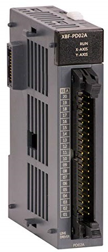
Parts name and Dimension (mm)
This is front part of the Module. Refer to each name when driving the system. For more information, refer to user manual.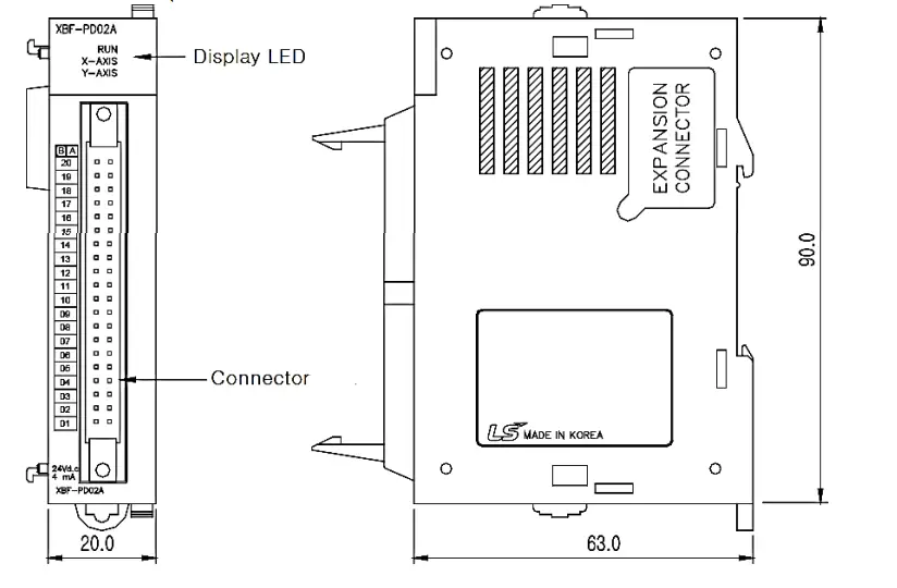
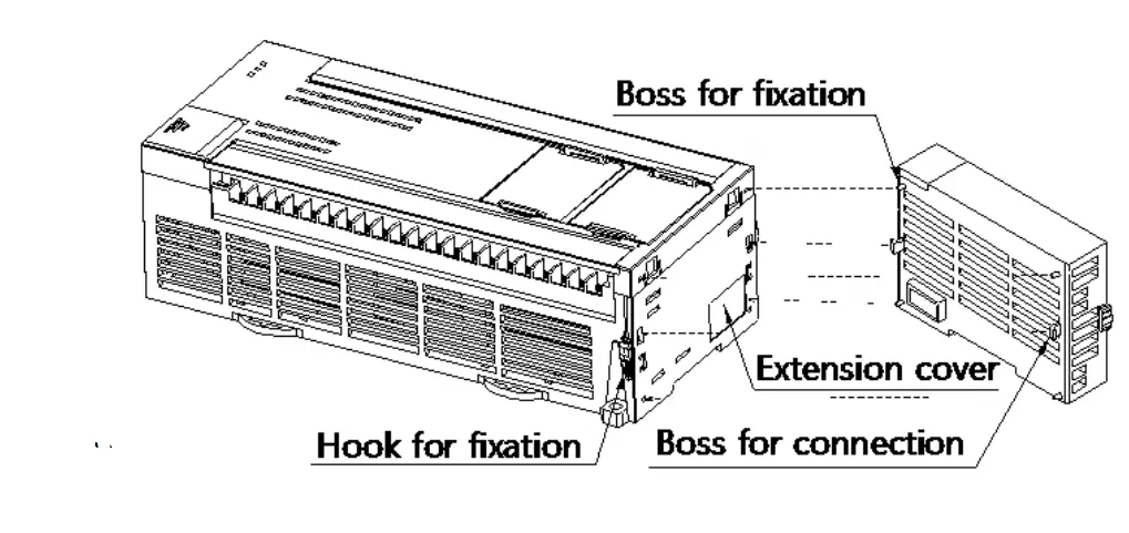
Installing / Removing Modules
Here describes the method to install each product each product.
- Installing module
- Eliminate the extension cover at the product.
- Push the product and connect it in agreement with hook for fixation of four edges and hook for connection at the bottom.
- After the connection, push down the hook for fixation and fix it completely.
- Removing module
- Push up the hook for disconnection,and then remove the product with two hands. (Do not remove the product by force)
- Push up the hook for disconnection,and then remove the product with two hands. (Do not remove the product by force)
Performance specifications
Performance specifications are as follows
| Type | Specifications |
| No. of control axis | 2 |
| Control method | Position control, Speed control, Speed/Position control, Position/Speed control |
| Connection | RS-232C port or USB of basic unit |
| Back-up | Saves parameter, operation data at flash memory |
Wiring
Precaution for wiring
- Don’t let AC power line near to analog input module’s external input signal line. With enough distance kept away between them, it will be free from surge or inductive noise.
- Cable shall be selected in due consideration of ambient temperature and allowable current. More than AWG22 (0.3㎟) is recommended.
- Don’t let the cable too close to hot device and material or in direct contact with oil for long, which will cause damage or abnormal operation due to short-circuit.
- Check the polarity when wiring the terminal.
- Wiring with a high-voltage line or power line may produce inductive hindrance causing abnormal operation or defect.
- Enable the channel that you want to use.
Wiring examples
- Interface with external
Item Pin No. Signal Signal direction module – external X Y Function for each axis B20 MPG A+ Manual pulse generator Encoder A+ input ß A20 MPG A- Manual pulse generator Encoder A- input ß B19 MPG B+ Manual pulse generator Encoder B+ input
ß A19 MPG B- Manual pulse generator Encoder B- input ß A18 B18 FP+ Pulse output (differential +) à A17 B17 FP- Pulse output (differential -) à A16 B16 RP+ Pulse sign (differential +) à A15 B15 RP- Pulse sign (differential -) à A14 B14 0V+ High limit ß A13 B13 0V- Low Limit ß A12 B12 DOG DOG ß A11 B11 NC Not used A10 B10 A9 B9 COM Common(OV+,OV-,DOG) ⇔ A8 B8 NC Not used A7 B7 INP In position signal ß A6 B6 INP COM DR/INP signal Common ⇔ A5 B5 CLR Deviation counter clear signal à A4 B4 CLR COM Deviation counter clear signal Common ⇔ A3 B3 HOME +5V Origin signal (+5V) ß A2 B2 HOME COM Origin signal (+5V) Common ⇔ A1 B1 NC Not used - Interface when you use I/O link board
Wiring can be easy by connecting the I/O link board and I/O connector when using XGB positioning module
When wiring XGB positioning module by using TG7-1H40S(I/O link) and C40HH-10SB-XBI(I/O connector), the relation between each terminal of I/O link board and I/O of the positioning module is as follows.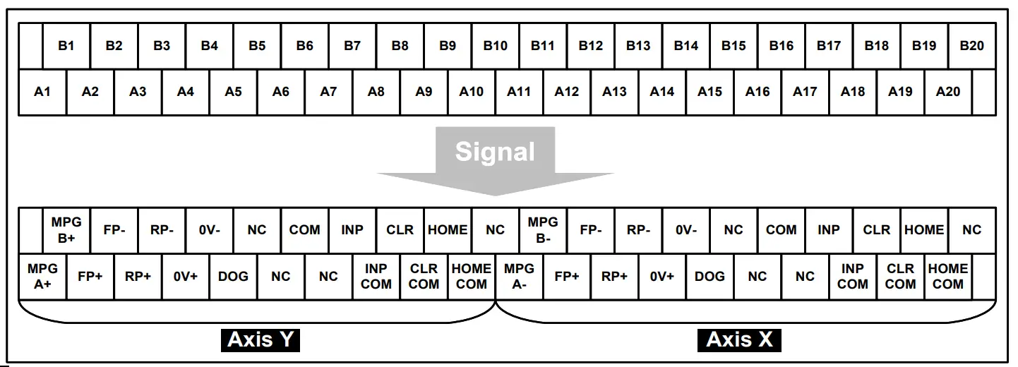
Warranty
- The warranty period is 36 months from the date of manufacture.
- The initial diagnosis of faults should be conducted by the user. However, upon request, LS ELECTRIC or its representative(s) can undertake this task for a fee. If the cause of the fault is found to be the responsibility of LS ELECTRIC, this service will be free of charge.
- Exclusions from warranty
- Replacement of consumable and life-limited parts (e.g. relays, fuses, capacitors, batteries, LCDs, etc.)
- Failures or damages caused by improper conditions or handling outside those specified in the user manual
- Failures caused by external factors unrelated to the product
- Failures caused by modifications without LS ELECTRIC’s consent
- Use of the product in unintended ways
- Failures that cannot be predicted/solved by current scientific technology at the time of manufacture
- Failures due to external factors such as fire, abnormal voltage, or natural disasters
- Other cases for which LS ELECTRIC is not responsible
- For detailed warranty information, please refer to the user’s manual.
- The content of the installation guide is subject to change without notice for product performance improvement.
LS ELECTRIC Co., Ltd. www.ls-electric.com 10310001005 V4.5 (2024.06)
- E-mail: automation@ls-electric.com
- Headquarter/Seoul Office Tel: 82-2-2034-4033,4888,4703
- LS ELECTRIC Shanghai Office (China) Tel: 86-21-5237-9977
- LS ELECTRIC (Wuxi) Co., Ltd. (Wuxi, China) Tel: 86-510-6851-6666
- LS ELECTRIC Vietnam Co., Ltd. (Hanoi, Vietnam) Tel: 84-93-631-4099
- LS ELECTRIC Middle East FZE (Dubai, U.A.E.) Tel: 971-4-886-5360
- LS ELECTRIC Europe B.V. (Hoofddorf, Netherlands) Tel: 31-20-654-1424
- LS ELECTRIC Japan Co., Ltd. (Tokyo, Japan) Tel: 81-3-6268-8241
- LS ELECTRIC America Inc. (Chicago, USA)Tel: 1-800-891-2941
- Factory: 56, Samseong 4-gil, Mokcheon-eup, Dongnam-gu, Cheonan-si, Chungcheongnam-do, 31226, Korea

Documents / Resources
 | LS XBF-PD02A Programmable Logic Controller [pdf] Installation Guide XBF-PD02A Programmable Logic Controller, XBF-PD02A, Programmable Logic Controller, Logic Controller, Controller |