![]() ACD/R-13A Three Position Temperature Controllers
ACD/R-13A Three Position Temperature Controllers
Instruction Manual
ACD/R-13A Three Position Temperature Controllers
COMMUNICATION INSTRUCTION MANUAL ACD/R-13A, ACD/R-15A (C, C5)
No. ACDR1CE8 2020.03
This manual contains instructions for communication functions of the ACD-13A, ACR-13A, ACD-15A and ACR-15A.
Serial communication and Console communication cannot be used together.
When performing Serial communication, remove the exclusive cable (CMB) from the USB port of the PC and console connector of the ACD/R-13A, ACD/R-15A.
When performing Console communication, it is not required to remove the Serial communication cables.
However, do not send a command from the master side.
System Configuration
1.1 RS-232C (C option)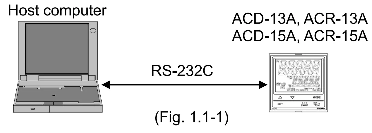 1.2 RS-485 Multi-Drop Connection Communication (C5 option)
Wiring
2.1 RS-232C (C option)
• D-sub 9-pin connector D-sub 25-pin connector
 2.2 RS-485 (C5 option)
• When using USB communication cable CMC-001-1 (sold separately) • When using communication converter IF-400 (sold separately)
Shield wire
Connect only one end of the shield to the FG or GND terminal to avoid a ground loop. If both ends of the shield wire are connected to the FG or GND terminal, the circuit will be closed, resulting in a ground loop.
This may cause noise.
Be sure to ground the FG or GND terminal.
Recommended cable: OTSC-VB 2PX0.5SQ (made by Onamba Co., Ltd.) or equivalent (Use a twisted pair cable.)
Terminator (Terminal resistor)
Communication converter IF-400 (sold separately) has a built-in terminator.
The terminator is mounted at the end of the wire when connecting multiple peripheral devices to a personal computer. The terminator prevents signal reflection and disturbance.
Do not connect a terminator to the communication line because each ACD/R-13A, ACD/R-15A has built-in pull-up and pull-down resistors.
Setting Communication Parameters
Set communication parameters following the procedure below.
(1)![]() Set the SET key 4 times in PV/SV Display Mode.
Set the SET key 4 times in PV/SV Display Mode.
The unit enters the Engineering group.
(2)![]() Press the MODE key. The unit proceeds to the Input group.
Press the MODE key. The unit proceeds to the Input group.
(3) ![]() Press theSET key several times until characters of the Communication group appear.
Press theSET key several times until characters of the Communication group appear.
(4) ![]() Press the MODE key.
Press the MODE key.
The unit proceeds to ‘Communication protocol’.
- To set each setting item, use the ▲or▼ key.
- If the MODE key is pressed, the set value is registered, and the unit proceeds to the next setting item.
If the MODE key is pressed at [SVTC bias], the unit proceeds to the ‘Communication protocol’. - Pressing the
 key reverts to the previous setting item.
 - Pressing the key for 1 sec reverts to the previous setting level (reverts from setting item to each group).
- If the MODE key is pressed for 3 seconds in any setting mode, the unit will revert to PV/SV Display Mode.
| Character | Name, Function, Setting Range | Factory Default |
 | Communication protocol | Shinko protocol |
| • Selects the communication protocol. | ||
 | Instrument number | 0 |
| • Sets the instrument number of this unit. (The instrument numbers should be set one by one when multiple instruments are connected in Serial communication, otherwise communication is impossible.) • Setting range: 0 to 95 | ||
 | Communication speed | 9600 bps |
| • Selects a communication speed equal to that of the host computer. When using IF-400 communication converter (sold separately), select 9600 bps or 19200 bps. | ||
 | Data bit/Parity | 7 bits/Even |
| • Selects data bit and parity. | ||
 | Stop bit | 1 |
| • Selects the stop bit. | ||
 | SVTC bias | 0c |
| • By connecting to Shinko programmable controllers PCA1 or PCB1 (select ‘SV digital transmission’ in [Communication protocol]), the step SV can be received from programmable controllers. See Section ‘8. SV Digital Transmission’. (pp.22, 23) •Control desired value (SV) adds SVTC bias value to the step SV. Set the value if necessary. • Available only when ‘Shinko protocol’ is selected in [Communication protocol]. • Setting range: Converted value of 20% of the input span DC voltage, current inputs: 20% of the scaling span (The placement of the decimal point follows the selection.) | ||
Communication Procedure
Communication starts with command transmission from the host computer (hereafter Master), and ends with the response of the ACD/R-13A, ACD/R-15A (hereafter Slave).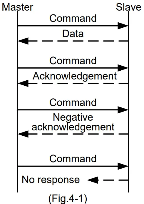
- Response with data
When the master sends the reading command, the slave responds with the corresponding set value or current status. - Acknowledgement
When the master sends the setting command, the slave responds by sending acknowledgement after the processing is terminated. - Negative acknowledgement
When the master sends a non-existent command or value out of the setting range, the slave returns a negative acknowledgement. - No response
The slave will not respond to the master in the following cases:- Global address (Shinko protocol) is set.
- Broadcast address (MODBUS protocol) is set.
- Communication error (framing error, parity error)
- Checksum error (Shinko protocol), LRC discrepancy (MODBUS ASCII mode), CRC-16 discrepancy (MODBUS RTU mode)
Communication timing of the RS-485
Master side (Take note while programming)
When the master starts transmission through the RS-485 communication line, the master is arranged so as to provide an idle status (mark status) transmission period of 1 or more characters before sending the command to ensure synchronization on the receiving side.
Set the program so that the master can disconnect the transmitter from the communication line within a 1 character transmission period after sending the command in preparation for reception of the response from the slave.
To avoid collision of transmissions between the master and the slave, send the next command after carefully checking that the master has received the response.
If a response to the command is not returned due to communication errors, set the Retry Processing to send the command again. (It is recommended to execute Retry twice or more.)
Slave side
When the slave starts transmission through the RS-485 communication line, the slave is arranged so as to provide an idle status (mark status) transmission period of 1 or more characters before sending the response to ensure synchronization on the receiving side.
The slave is arranged so as to disconnect the transmitter from the communication line within a 1 character transmission period after sending the response.
Shinko Protocol
5.1 Transmission Mode
Shinko protocol is composed of ASCII.
Hexadecimal (0 to 9, A to F), which is divided into high order (4-bit) and low order (4-bit) out of 8-bit
binary data in command is transmitted as ASCII characters.
Data format: Start bit: 1 bit
Data bit: 7 bits
Parity: Even
Stop bit: 1 bit
Error detection: Checksum
5.2 Command Configuration
All commands are composed of ASCII.
The data (set value, decimal number) is represented by hexadecimal numbers.
Negative numbers are represented by 2’s complement.
Numerals written below the command represent number of characters.
(1) Setting command
| Header (02H) | Address | Sub address (20H) | Command type (50H) | Data item | Data | Checksum | Delimiter(03H) |
| 1 | 1 | 1 | 1 | 4 | 4 | 2 | 1 |
(2) Reading command
| Header (02H) | Address | Sub address (20H) | Command type (20H) | Data item | Checksum | Delimiter (03H) |
| 1 | 1 | 1 | 1 | 4 | 2 | 1 |
(3) Response with data
| Header (06H) | Address | Sub address (20H) | Command type (20H) | Data item | Data | Checksum | Delimiter (03H) |
| 1 | 1 | 1 | 1 | 4 | 4 | 2 | 1 |
(4) Acknowledgement
| Header (06H) | Address | Checksum | Delimiter (03H) |
| 1 | 1 | 2 | 1 |
(5) Negative acknowledgement
| Header (15H) | Address | Error code | Checksum | Delimiter (03H) |
| 1 | 1 | 1 | 2 | 1 |
| Header: | Control code to represent the beginning of the command or the response. ASCII is used. Setting command, Reading command: STX (02H) fixed Response with data, Acknowledgement: ACK (06H) fixed Negative acknowledgement: NAK (15H) fixed |
| Instrument number (Address): | Numbers by which the master discerns each slave. Instrument number 0 to 94 and Global address 95. ASCII (20H to 7FH) is used by adding 20H to instrument numbers 0 to 95 (00H to 5FH). 95 (7FH) is called Global address, which is used when the same command is sent to all the slaves connected. However, the response is not returned. |
| Sub address: | 20H fixed |
| Command type: | Code to discern Setting command (50H) and Reading command (20H) |
| Data item: | Classification of the command object. Composed of 4-digit hexadecimal numbers, using ASCII. (Refer to “7. Communication Command Table”.) |
| Data: | The contents of data (set value) differs depending on the setting command. Composed of 4-digit hexadecimal numbers, using ASCII. (Refer to “7. Communication Command Table”.) |
| Checksum: | 2-character data to detect communication errors. (Refer to “5.3 Checksum Calculation”.) |
| Delimiter: | Control code to represent the end of command ASCII code ETX (03H) fixed |
| Error code: | Represents an error type using ASCII. 1 (31H)—–Non-existent command 2 (32H)—–Not used 3 (33H)—–Setting outside the setting range 4 (34H)—–Status unable to be set (e.g. AT is performing) 5 (35H)—–During setting mode by keypad operation |
5.3 Checksum Calculation
Checksum is used to detect receiving errors in the command or data.
Set the program for the master side as well to calculate the checksum of the response data from the slaves so that communication errors can be checked.
The ASCII code (hexadecimal) corresponding to the characters which range from the address (instrument number) to that before the checksum is converted to binary notation, and the total value is calculated.
The lower one byte of the total value is converted to 2’s complement, and then to hexadecimal numbers, that is, ASCII code for the checksum.
- 1’s complement: Reverse each binary bit. 0 will become 1 and vice versa.
- 2’s complement: Add 1 to 1’s complement.
Checksum calculation example
SV: 600 (0258H)
Address (instrument number): 0 (20H)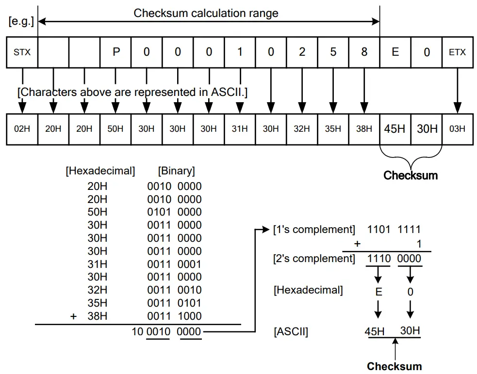 5.4 Command Example
Numerals written below the command represent the number of characters.
(1) Read (Address 1, PV)
• Reading command from the master
| Header(02H) | Address(21H) | Sub address (20H) | Command type (20H) | Data item [0A00H] (30H 41H 30H 30H) | Checksum (43H 45H) | Delimiter (03H) |
| 1 | 1 | 1 | 1 | 4 | 2 | 1 |
A response from the slave in normal status [When PV=600ºc (0258H)]
| Header (06H) | Address (21H) | Sub address (20H) | Command type (20H) | Data item [0A00H] (30H 41H 30H 30H) | Data [0258H] (30H 32H 35H 38H) | Checksum (46H 46H) | Delimiter (03H) |
| 1 | 1 | 1 | 1 | 4 | 4 | 2 | 2 |
(2) Reading (Address 1, SV)
• Reading command from the master
| Header (02H) | Address (21H) | Sub address (20H) | Command type (20H) | Data item [0001H] (30H 30H 30H 31H) | Checksum (44H 45H) | Delimiter (03H) |
| 1 | 1 | 1 | 1 | 4 | 2 | 1 |
• A response from the slave in normal status [When SV=600ºc (0258H)]
| Header (06H) | Address (21H) | Sub address (20H) | Command type (20H) | Data item [0001H] (30H 30H 30H 31H) | Data [0258H] (30H 32H 35H 38H) | Checksum (30H 46H) | Delimiter (03H) |
| 1 | 1 | 1 | 1 | 4 | 4 | 2 | 1 |
(3) Setting (Address 1, SV) [when setting SV to 600ºc (0258H)] • Setting command from the master
| Header (02H) | Address (21H) | Sub address (20H) | Command type (50H) | Data item [0001H] (30H 30H 30H 31H) | Data [0258H] (30H 32H 35H 38H) | Checksum (44H 46H) | Delimiter (03H) |
| 1 | 1 | 1 | 1 | 4 | 4 | 2 | 1 |
• A response from the slave in normal status
| Header (06H) | Address (21H) | Checksum (44H 46H) | Delimiter (03H) |
| 1 | 1 | 2 | 1 |
MODBUS Protocol
6.1 Transmission Mode
There are 2 transmission modes (ASCII and RTU) in MODBUS protocol.
6.1.1 ASCII Mode
Hexadecimal (0 to 9, A to F), which is divided into high order (4-bit) and low order (4-bit) out of 8-bit binary data in command is transmitted as ASCII characters.
Data format Start bit: 1 bit
Data bit: 7 bits (8 bits) (Selectable)
Parity: Even (No parity, Odd) (Selectable)
Stop bit: 1 bit (2 bits) (Selectable)
Error detection: LRC (Longitudinal Redundancy Check)
6.1.2 RTU Mode
8-bit binary data in command is transmitted as it is.
Data format Start bit: 1 bit
Data bit: 8 bits
Parity: No parity (Even, Odd) (Selectable)
Stop bit: 1 bit (2 bits) (Selectable)
Error detection: CRC-16 (Cyclic Redundancy Check)
6.2 Data Communication Interval
6.2.1 ASCII Mode
1 second or less (Max.1 second of interval between characters)
6.2.2 RTU Mode
3.5 character transmission times or less
To transmit continuously, an interval between characters which consist of one message, must be within 3.5 character transmission times.
If an interval lasts longer than 3.5 character transmission times, the instrument assumes that transmission from the master is finished, resulting in a communication error, and will not return a response.
6.3 Message Configuration
6.3.1 ASCII Mode
ASCII mode message is configured to start by Header [: (colon) (3AH)] and end by Delimiter [CR (carriage return) (0DH) + LF (Line feed) (0AH)].
| Header (:) | Slave address | Function code | Data | Error check LRC | Delimiter (CR) | Delimiter (LF) |
6.3.2 RTU Mode
RTU mode is configured to start after idle time is processed for more than 3.5 character transmissions, and end after idle time is processed for more than 3.5 character transmissions.
| 3.5 idle characters | Slave address | Function code | Data | Error check CRC-16 | 3.5 idle characters |
(1) Slave address
Slave address is an individual instrument number on the slave side, and is set within the range 0 to 95 (00H to 5FH).
The master identifies slaves by the slave address of the requested message.
The slave informs the master which slave is responding to the master by placing its own address in the response message.
Slave address 00H (Broadcast address) can identify all the slaves connected. However, slaves do not respond.
(2) Function code
The function code is the command code for the slave to undertake one of the following actions.
| Function Code | Contents |
| 03 (03H) | Reading the set value and information from slaves |
| 06 (06H) | Setting to slaves |
Function code is used to discern whether the response is normal (acknowledgement) or if any error (negative acknowledgement) has occurred when the slave returns the response message to the master. When acknowledgement is returned, the slave simply returns the original function code.
When negative acknowledgement is returned, the MSB of the original function code is set as 1 for the response. For example, if the master sends request message setting 10H to the function code by mistake, slave returns 90H by setting the MSB to 1, because the former is an illegal function.
For negative acknowledgement, the exception codes below are set to the data of the response message, and returned to the master in order to inform it of what kind of error has occurred.
| Exception Code | Contents |
| 1 (01H) | Illegal function (Non-existent function) |
| 2 (02H) | Illegal data address (Non-existent data address) |
| 3 (03H) | Illegal data value (Value out of the setting range) |
| 17 (11H) | Shinko protocol error code 4 [Status unable to be set, (e.g.) AT is performing] |
| 18 (12H) | Shinko protocol error code 5 (During setting mode by keypad operation) |
(3) Data
Data differs depending on the function code.
A request message from the master is composed of data item, number of data and setting data.
A response message from the slave is composed of the byte count, data and exception codes in negative acknowledgements, corresponding to the request message. The number of data to be dealt within one message is “1”. Therefore, the number of data is fixed as (30H)(30H)(30H)(31H).
Effective range of data is -32768 to 32767 (8000H to 7FFFH).
(4) Error check
ASCII Mode
After calculating LRC (Longitudinal Redundancy Check) from the slave address to the end of data, the calculated 8-bit data is converted to two ASCII characters, and are appended to the end of message.
How to Calculate LRC
- Create a message in RTU mode.
- Add all the values from the slave address to the end of data. This is assumed as X.
- Make a complement for X (bit reverse). This is assumed as X.
- Add a value of 1 to X. This is assumed as X.
- Set X as an LRC to the end of the message.
- Convert the whole message to ASCII characters.
RTU Mode
After calculating CRC-16 (Cyclic Redundancy Check) from the slave address to the end of the data, the calculated 16-bit data is appended to the end of message in sequence from low order to high order.
How to calculate CRC-16
In the CRC-16 system, the information is divided by the polynomial series. The remainder is added to the end of the information and transmitted. The generation of a polynomial series is as follows.
(Generation of polynomial series: X16 + X 15 + X 2 + 1)
- Initialize the CRC-16 data (assumed as X) (FFFFH).
- Calculate exclusive OR (XOR) with the 1st data and X. This is assumed as X.
- Shift X one bit to the right. This is assumed as X.
- When a carry is generated as a result of the shift, XOR is calculated by X of 3 and the fixed value (A001H). This is assumed as X. If a carry is not generated, go to step 5.
- Repeat steps 3 and 4 until shifting 8 times.
- XOR is calculated with the next data and X. This is assumed as X.
- Repeat steps 3 to 5.
- Repeat steps 3 to 5 up to the final data.
- Set X as CRC-16 to the end of message in sequence from low order to high order.
6.4 Message Example
6.4.1 ASCII Mode
Numerals written below the message represent the number of characters.
(1) Reading (Slave address 1, PV)
• A request message from the master
Amount of data means how many data items are to be read. It is fixed as 1 (30H 30H 30H 31H).
| Header (3AH) | Slave address (30H 31H) | Function code (30H 33H) | Data item [0A00H] (30H 41H 30H 30H) | Amount of data [0001H] (30H 30H 30H 31H) | Error check LRC (46H 31H) | Delimiter CR+LF (0DH 0AH) |
| 1 | 2 | 2 | 4 | 4 | 2 | 2 |
• Response message from the slave in normal status [When PV=600 (0258H)] The response byte count means the byte count of data which have been read. It is fixed as 2 (30H 32H).
| Header (3AH) | Slave address (30H 31H) | Function code (30H 33H) | Response byte count [02H] (30H 32H) | Data [0258H] (30H 32H 35H 38H) | Error check LRC (41H 30H) | Delimiter CR+LF (0DH 0AH) |
| 1 | 2 | 2 | 2 | 4 | 2 | 2 |
(2) Reading (Slave address 1, SV)
• A request message from the master
Amount of data means how many data items are to be read. It is fixed as 1 (30H 30H 30H 31H).
| Header (3AH) | Slave address (30H 31H) | Function code (30H 33H) | Data item [0001H] (30H 30H 30H 31H) | Amount of data [0001H] (30H 30H 30H 31H) | Error check LRC (46H 41H) | Delimiter CR+LF (0DH 0AH) |
| 1 | 2 | 2 | 4 | 4 | 2 | 2 |
• Response message from the slave in normal status [When SV=600 (0258H)] The response byte count means the byte count of data which have been read. It is fixed as 2 (30H 32H).
| Header (3AH) | Slave address (30H 31H) | Function code (30H 33H) | Response byte count [02H] (30H 32H) | Data [0258H] (30H 32H 35H 38H) | Error check LRC (41H 30H) | Delimiter CR+LF (0DH 0AH) |
| 1 | 2 | 2 | 2 | 4 | 2 | 2 |
• Response message from the slave in exception (error) status (When a data item has been mistaken)
The function code MSB is set to 1 for the response message in exception (error) status [83H (38H 33H)]. The exception code 02H (30H 32H: Non-existent data address) is returned (error).
| Header (3AH) | Slave address (30H 31H) | Function code (38H 33H) | Exception code [02H] (30H 32H) | Error check LRC (37H 41H) | Delimiter CR+LF (0DH 0AH) |
| 1 | 2 | 2 | 2 | 2 | 2 |
(3) Setting (Slave address 1, SV) [When setting SV to 600 (0258H)]
• A request message from the master
| Header (3AH) | Slave address (30H 31H) | Function code (30H 36H) | Data item [0001H] (30H 30H 30H 31H) | Data [0258H] (30H 32H 35H 38H) | Error check LRC (39H 45H) | Delimiter CR+LF (0DH 0AH) |
| 1 | 2 | 2 | 4 | 4 | 2 | 2 |
• Response message from the slave in normal status
| Header (3AH) | Slave address (30H 31H) | Function code (30H 36H) | Data item [0001H] (30H 30H 30H 31H) | Data [0258H] (30H 32H 35H 38H) | Error check LRC (39H 45H) | Delimiter CR+LF (0DH 0AH) |
| 1 | 2 | 2 | 4 | 4 | 2 | 2 |
• Response message from the slave in exception (error) status (When a value out of the setting range is set)
The function code MSB is set to 1 for the response message in exception (error) status [86H (38H 36H)].
The exception code 03H (30H 33H: Value out of the setting range) is returned (error).
| Header (3AH) | Slave address (30H 31H) | Function code (38H 36H) | Exception code [03H] (30H 33H) | Error check LRC (37H 36H) | Delimiter CR+LF (0DH 0AH) |
| 1 | 2 | 2 | 2 | 2 | 2 |
6.4.2 RTU Mode
Numerals written below the message represent the number of characters.
(1) Reading (Slave address 1, PV)
• A request message from the master
Amount of data means the data item to be read, and it is fixed as 1 (0001H).
| 3.5 idle characters | Slave address (01H) | Function code (03H) | Data item (0A00H) | Amount of data (0001H) | Error check CRC-16 (87D2H) | 3.5 idle characters |
| 1 | 1 | 2 | 2 | 2 |
• Response message from the slave in normal status [When PV=600ºc (0258H)] The response byte count means the byte count of data which have been read. It is fixed as 2 (02H).
| 3.5 idle characters | Slave address (01H) | Function code (03H) | Response byte count (02H) | Data (0258H) | Error check CRC-16 (B8DEH) | 3.5 idle characters |
| 1 | 1 | 1 | 2 | 2 |
(2) Reading (Slave address 1, SV)
• A request message from the master
Amount of data means the data item to be read, and it is fixed as 1 (0001H).
| 3.5 idle characters | Slave address (01H) | Function code (03H) | Data item (0001H) | Amount of data (0001H) | Error check CRC-16 (D5CAH) | 3.5 idle characters |
| 1 | 1 | 2 | 2 | 2 |
• Response message from the slave in normal status [When SV=600ºc (0258H)] The response byte count means the byte count of data which have been read. It is fixed as 2 (02H).
| 3.5 idle characters | Slave address (01H) | Function code (03H) | Response byte count (02H) | Data (0258H) | Error check CRC-16 (B8DEH) | 3.5 idle characters |
| 1 | 1 | 1 | 2 | 2 |
• Response message from the slave in exception (error) status (When a data item is incorrect)
The function code MSB is set to 1 for the response message in exception (error) status (83H).
The exception code (02H: Non-existent data address) is returned (error).
| 3.5 idle characters | Slave address (01H) | Function code (83H) | Exception code (02H) | Error check CRC-16 (C0F1H) | 3.5 idle characters |
| 1 | 1 | 1 | 2 |
(3) Setting (Slave address 1, SV) [When setting SV to 600ºc (0258H)] • A request message from the master
| 3.5 idle characters | Slave address (01H) | Function code (06H) | Data item (0001H) | Data (0258H) | Error check CRC-16 (D890H) | 3.5 idle characters |
| 1 | 2 | 2 | 2 | 2 |
• Response message from the slave in normal status
| 3.5 idle characters | Slave address (01H) | Function code (06H) | Data item (0001H) | Data (0258H) | Error check CRC-16 (D890H) | 3.5 idle characters |
| 1 | 1 | 2 | 2 | 2 |
• Response message from the slave in exception (error) status (When a value out of the setting range is set)
The function code MSB is set to 1 for the response message in exception (error) status (86H).
The exception code (03H: Value out of the setting range) is returned (error).
| 3.5 idle characters | Slave address (01H) | Function code (86H) | Exception code (03H) | Error check CRC-16 (0261H) | 3.5 idle characters |
| 1 | 1 | 1 | 2 |
Communication Command Table
About Data
Notes about setting and reading commands
- [13A] is entered in the Data item for the exclusive commands of the ACD/R-13A.
[15A] is entered in the Data item for the exclusive commands of the ACD/R-15A.
[13A] or [15A] is not entered in the Data Item for common commands to ACD/R-13A, ACD/R-15A.
Be sure to use exclusive commands correctly as described above, otherwise actions will not be guaranteed. - The data (set value, decimal) is converted to hexadecimal numbers. Negative numbers are represented by 2’s complement.
- When connecting multiple slaves, the address (instrument number) must not be duplicated.
- Do not use undefined Data items. If they are used, negative acknowledgement will be returned or a random value will be set or read, resulting in malfunction.
- MODBUS protocol uses Holding Register addresses. The Holding Register addresses are created as follows. A Shinko command Data item is converted to decimal number, and the offset of 40001 is added.
The result is the Holding Register address.
Using Data item 0001H SV [Set value memory number 1 (SM1)] as an example: Data item in the sending message is 0001H, however, MODBUS protocol Holding Register address is 40002 (1 + 40001).
Setting command
- Up to 1,000,000 (one million) entries can be stored in non-volatile IC memory.
If the number of settings exceeds the limit, the data will not be saved. So ensure the set values are not frequently changed via the software. (If the value set via the software is the same as the value before the setting, the value will not be set in non-volatile IC memory.) - Setting range of each item (via the software) is the same as when setting via the keypad.
- When the data (set value) has a decimal point, a whole number (hexadecimal) without a decimal point is used.
- If the alarm type is changed in [Event output EVT1 allocation (0060H)] to [Event output EVT5 allocation (0064H)], the alarm value will default to 0 (zero). Alarm output status will also return to the factory default.
- Settings via software communication are possible even in the Set value lock status.
- Even if options are not ordered, setting or reading via software communication will be possible.
However, their command contents will not function. - Communication parameters such as Instrument Number, Communication Speed of the slave cannot be set using the software. They can only be set via the keypad. See p.3.
- When sending a setting command using the Global address [95 (7FH), Shinko protocol] or Broadcast address [(00H) MODBUS protocol], the command is sent to all the connected slaves. However, no response is returned.
Reading command
- When the data (set value) has a decimal point, a whole number (hexadecimal) without a decimal point is used for a response.
Negative acknowledgement
The slave will return Error code 1 (31H, Shinko protocol) or Exception code 1 (01H, MODBUS protocol) in the following cases.
- If AT/Auto-reset (0010H) is selected while control is in PI control or in ON/OFF control action.
- When Manual MV (00D3H) is read during automatic control.
The slave will return Error code 4 (34H, Shinko protocol) or Exception code 17 (11H, MODBUS protocol) in the following cases.
- When SV (00D0H) of current Set value memory number is set during AT or program control.
- When manual MV (00D3H) is set during automatic control.
| Shinko Command Type | MODBUS Function Code | Data Item | Data | |
| 20H/50H | 03H/06H | 0001H | SV [Set value memory number 1 (SM1)] | Set value (Decimal point ignored.) |
| 20H/50H | 03H/06H | 0002H | EVT1 alarm value (SM1) | Set value (Decimal point ignored.) |
| 20H/50H | 03H/06H | 0003H | EVT1 high limit alarm value (SM1) | Set value (Decimal point ignored.) |
| 20H/50H | 03H/06H | 0004H | EVT2 alarm value (SM1) [13A] | Set value (Decimal point ignored.) |
| 20H/50H | 03H/06H | 0005H | EVT2 high limit alarm value (SM1) [13A] | Set value (Decimal point ignored.) |
| 20H/50H | 03H/06H | 0006H | EVT3 alarm value (SM1) [13A] | Set value (Decimal point ignored.) |
| 20H/50H | 03H/06H | 0007H | EVT3 high limit alarm value (SM1) [13A] | Set value (Decimal point ignored.) |
| 20H/50H | 03H/06H | 0008H | EVT4 alarm value (SM1) | Set value (Decimal point ignored.) |
| 20H/50H | 03H/06H | 0009H | EVT4 high limit alarm value (SM1) | Set value (Decimal point ignored.) |
| 20H/50H | 03H/06H | 000AH | EVT5 alarm value (SM1) | Set value (Decimal point ignored.) |
| 20H/50H | 03H/06H | 000BH | EVT5 high limit alarm value (SM1) | Set value (Decimal point ignored.) |
| Note: If independent alarms (such as High/Low limits independent, High/Low limit range independent and High/Low limits with standby independent) are selected in [EVT1 to EVT5 allocation (0060H to 0064H)], the EVT1 to EVT5 alarm value (SM1) matches the low limit side, and EVT1 to EVT5 high limit alarm value (SM1) matches the high limit side. The set values of the Set value memory numbers (SM1 to SM15) are common to those of step numbers (1 to 15) of the Program control command. (p.19) For Set value memory numbers (SM2 to SM15), use step numbers (2 to 15) of the Program control command. | ||||
| 20H/50H | 03H/06H | 0010H | AT/Auto-reset | 0000H: Cancel 0001H: Perform |
| 20H/50H | 03H/06H | 0011H | AT bias | Set value |
| 20H/50H | 03H/06H | 0020H | OUT1 proportional band (Zone 1) [13A] Proportional band (Zone 1) [15A] | Set value (Decimal point ignored.) |
| 20H/50H | 03H/06H | 0021H | OUT2 proportional band (Zone 1) [13A] | Set value (Decimal point ignored.) |
| 20H/50H | 03H/06H | 0022H | Integral time (Zone 1) | Set value |
| 20H/50H | 03H/06H | 0023H | Derivative time (Zone 1) | Set value |
| 20H/50H | 03H/06H | 0024H | ARW (Zone 1) | Set value |
| 20H/50H | 03H/06H | 0025H | Manual reset (Zone 1) | Set value (Decimal point ignored.) |
| 20H/50H | 03H/06H | 0026H | OUT1 rage-of-change (Zone 1) [13A] MV rage-of-change (Zone 1) [15A] | Set value |
| Note: The set valuesfrom Zones 1 to 5 are common to those of Zones 1 to 5 of the PID zone command. (Pages 20, 21) For Zones 2 to 5, use Zones 2 to 5 of the PID zone command. | ||||
| 20H/50H | 03H/06H | 0030H | Input type | 0000H: K -200 to 1370ºC 0001H: K -200.0 to 400.0ºC 0002H: J -200 to 1000ºC 0003H: R 0 to 1760ºC 0004H: S 0 to 1760ºC 0005H: B 0 to 1820ºC 0006H: E -200 to 800ºC 0007H: T -200.0 to 400.0ºC 0008H: N -200 to 1300ºC 0009H: PL- 0 to 1390ºC 000AH: C(W/Re5-26) 0 to 2315ºC 000BH: Pt100 -200.0 to 850.0ºC 000CH: JPt100 -200.0 to 500.0ºC 000DH: Pt100 -200 to 850ºC 000EH: JPt100 -200 to 500ºC 000FH: Pt100 -100.0 to 100.0ºC 0010H:JPt100 -100.0 to 500.0 ºC 0011H: K -328 to 2498ºF 0012H: K -328.0 to 752.0ºF 0013H: J -328 to 1832ºF 0014H: R 32 to 3200ºF 0015H: S 32 to 3200ºF 0016H: B 32 to 3308ºF 0017H: E -328 to 1472ºF 0018H: T -328.0 to 752.0ºF 0019H: N -328 to 2372ºF 001AH: PL- 32 to 2534ºF 001BH: C(W/Re5-26) 32 to 4199ºF 001CH: Pt100 -328.0 to 1562.0ºF 001DH: JPt100 -328.0 to 932.0ºF 001EH: Pt100 -328 to 1562ºF 001FH: JPt100 -328 to 932ºF 0020H: Pt100 -148.0 to 212.0ºF 0021H: JPt100 -148.0 to 932.0 ºF 0022H: 4 to 20 mA DC -2000 to 10000 0023H: 0 to 20 mA DC -2000 to 10000 0024H: 0 to 10 mV DC -2000 to 10000 0025H: -10 to 10 mV DC -2000 to 10000 0026H: 0 to 50 mV DC -2000 to 10000 0027H: 0 to 100 mV DC -2000 to 10000 0028H: 0 to 1 V DC -2000 to 10000 0029H: 0 to 5 V DC -2000 to 10000 002AH: 1 to 5 V DC -2000 to 10000 002BH: 0 to 10 V DC -2000 to 10000 |
| Note: When responding to the command of Input type, it takes approx. 2 seconds due to internal processing. Therefore, set the Time-out time for communication to 2 seconds or more when executing this command. | ||||
| 20H/50H | 03H/06H | 0031H | Scaling high limit | Set value (Decimal point ignored.) |
| 20H/50H | 03H/06H | 0032H | Scaling low limit | Set value (Decimal point ignored.) |
| 20H/50H | 03H/06H | 0033H | Decimal point place | 0000H: xxxxx 0001H: xxxx.x 0002H: xxx.xx 0003H: xx.xxx 0004H: x.xxxx |
| 20H/50H | 03H/06H | 0034H | PV filter time constant | Set value (Decimal point ignored.) |
| 20H/50H | 03H/06H | 0035H | Sensor correction | Set value (Decimal point ignored.) |
| 20H/50H | 03H/06H | 0040H | OUT1 proportional cycle [13A] | Set value |
| 20H/50H | 03H/06H | 0041H | OUT2 proportional cycle [13A] | Set value |
| 20H/50H | 03H/06H | 0042H | OUT1 high limit [13A] MV high limit [15A] | Set value |
| 20H/50H | 03H/06H | 0043H | OUT1 low limit [13A] MV low limit [15A] | Set value |
| 20H/50H | 03H/06H | 0044H | OUT1 ON/OFF hysteresis [13A] ON/OFF hysteresis [15A] | Set value (Decimal point ignored.) |
| 20H/50H | 03H/06H | 0045H | OUT2 cooling method [13A] | 0000H: Air cooling 0001H: Oil cooling 0002H: Water cooling |
| 20H/50H | 03H/06H | 0046H | OUT2 high limit [13A] | Set value |
| 20H/50H | 03H/06H | 0047H | OUT2 low limit [13A] | Set value |
| 20H/50H | 03H/06H | 0048H | Overlap/Dead band [13A] | Set value (Decimal point ignored.) |
| 20H/50H | 03H/06H | 0049H | OUT2 ON/OFF hysteresis [13A] | Set value (Decimal point ignored.) |
| 20H/50H | 03H/06H | 004AH | Direct/Reverse action | 0000H: Reverse action 0001H: Direct action |
| 20H/50H | 03H/06H | 004BH | OUT1 MV preset output [13A] | Set value (Decimal point ignored.) |
| 20H/50H | 03H/06H | 004CH | OUT2 MV preset output [13A] | Set value (Decimal point ignored.) |
| 20H/50H | 03H/06H | 0050H | Event input EVI1 allocation | 0000H: No event 0001H: Set value memory 0002H: Control ON/OFF 0003H: Direct/Reverse action 0004H: Timer Start/Stop 0005H: PV display; PV holding 0006H: PV display; PV peak value holding 0007H: Preset output 1 0008H: Auto/Manual control 0009H: Remote/Local 000AH: Program mode; RUN/STOP 000BH: Program mode; Holding/Not holding 000CH: Program mode; Advance function 000DH: Integral action holding 000EH: Preset output 2 |
| 20H/50H | 03H/06H | 0051H | Event input EVI2 allocation | Same as those of Event input EVI1 allocation |
| 20H/50H | 03H/06H | 0052H | Event input EVI3 allocation | Same as those of Event input EVI1 allocation |
| 20H/50H | 03H/06H | 0053H | Event input EVI4 allocation | Same as those of Event input EVI1 allocation |
| 20H/50H | 03H/06H | 0060H | Event output EVT1 allocation | 0000H: No event 0001H: Alarm output, High limit alarm 0002H: Alarm output, Low limit alarm 0003H: Alarm output, High/Low limits alarm 0004H: Alarm output, H/L limits independent 0005H: Alarm output, H/L limit range alarm 0006H: Alarm output, H/L limit range independent 0007H: Alarm output, Process high alarm 0008H: Alarm output, Process low alarm 0009H: Alarm output, High limit with standby 000AH: Alarm output, Low limit with standby 000BH: Alarm output, H/L limits with standby 000CH: Alarm output, H/L limits with standby independent 000DH: Timer output linked with Event input 000EH: Timer output linked with Event input. Control ON during timer operation. Control OFF after time is up. 000FH: Heater burnout alarm output 0010H: Loop break alarm output 0011H: Time signal output 0012H: Output during AT 0013H: Pattern end output |
| 20H/50H | 03H/06H | 0061H | Event output EVT2 allocation [13A] | Same as those of Event output EVT1 allocation |
| 20H/50H | 03H/06H | 0062H | Event output EVT3 allocation [13A] | Same as those of Event output EVT1 allocation |
| 20H/50H | 03H/06H | 0063H | Event output EVT4 allocation | Same as those of Event output EVT1 allocation |
| 20H/50H | 03H/06H | 0064H | Event output EVT5 allocation | Same as those of Event output EVT1 allocation |
| 20H/50H | 03H/06H | 0065H | EVT1 alarm hysteresis | Set value (Decimal point ignored.) |
| 20H/50H | 03H/06H | 0066H | EVT1 alarm delay time | Set value |
| 20H/50H | 03H/06H | 0067H | EVT1 alarm Energized/De-energized | 0000H: Energized 0001H: De-energized |
| 20H/50H | 03H/06H | 0068H | EVT2 alarm hysteresis [13A] | Set value (Decimal point ignored.) |
| 20H/50H | 03H/06H | 0069H | EVT2 alarm delay time [13A] | Set value |
| 20H/50H | 03H/06H | 006AH | EVT2 alarm Energized/De-energized [13A] | 0000H: Energized 0001H: De-energized |
| 20H/50H | 03H/06H | 006BH | EVT3 alarm hysteresis [13A] | Set value (Decimal point ignored.) |
| 20H/50H | 03H/06H | 006CH | EVT3 alarm delay time [13A] | Set value |
| 20H/50H | 03H/06H | 006DH | EVT3 alarm Energized/De-energized [13A] | 0000H: Energized 0001H: De-energized |
| 20H/50H | 03H/06H | 006EH | EVT4 alarm hysteresis | Set value (Decimal point ignored.) |
| 20H/50H | 03H/06H | 006FH | EVT4 alarm delay time | Set value |
| 20H/50H | 03H/06H | 0070H | EVT4 alarm Energized/De-energized | 0000H: Energized 0001H: De-energized |
| 20H/50H | 03H/06H | 0071H | EVT5 alarm hysteresis | Set value (Decimal point ignored.) |
| 20H/50H | 03H/06H | 0072H | EVT5 alarm delay time | Set value |
| 20H/50H | 03H/06H | 0073H | EVT5 alarm Energized/De-energized | 0000H: Energized 0001H: De-energized |
| 20H/50H | 03H/06H | 0074H | Timer output delay action | 0000H: ON delay time 0001H: OFF delay time 0002H: ON/OFF delay time |
| 20H/50H | 03H/06H | 0075H | Timer output time unit | 0000H: Minutes 0001H: Seconds |
| 20H/50H | 03H/06H | 0076H | OFF delay time | Set value |
| 20H/50H | 03H/06H | 0077H | ON delay time | Set value |
| 20H/50H | 03H/06H | 0078H | Heater rated current [13A] | 0000H: 20 A 0001H: 100 A |
| 20H/50H | 03H/06H | 0079H | Heater burnout alarm 1 value[13A] | Set value (Decimal point ignored.) |
| 20H/50H | 03H/06H | 007AH | Heater burnout alarm 2 value[13A] | Set value (Decimal point ignored.) |
| 20H/50H | 03H/06H | 007BH | Loop break alarm time | Set value |
| 20H/50H | 03H/06H | 007CH | Loop break alarm band | Set value (Decimal point ignored.) |
| 20H/50H | 03H/06H | 007DH | Time signal output step | Set value |
| 20H/50H | 03H/06H | 007EH | Time signal output OFF time | Set value |
| 20H/50H | 03H/06H | 007FH | Time signal output ON time | Set value |
| Note: For Time Signal output OFF/ON time setting, the smaller unit value of Step time unit (0091H) is calculated, and is converted to hexadecimal numbers. 00:00 to 99:59 (0 to 5999) (e.g.) When time unit is set to “Hours:Minutes”: 1 hour 30 minutes→ 90 minutes→ 005AH 15 hours 50 minutes → 950 minutes → 03B6H | ||||
| 20H/50H | 03H/06H | 0090H | Fixed value control/Program control | 0000H: Fixed value control 0001H: Program control |
| 20H/50H | 03H/06H | 0091H | Step time unit | 0000H: Hours:Minutes 0001H: Minutes:Seconds |
| 20H/50H | 03H/06H | 0092H | Power restore action | 0000H: Stops (in standby) after power is restored. 0001H: Continues (resumes) after power is restored. 0002H: Suspended (on hold) after power is restored. |
| 20H/50H | 03H/06H | 0093H | Program start temperature | Set value (Decimal point ignored.) |
| 20H/50H | 03H/06H | 00A0H | Remote/Local | 0000H: Local 0001H: Remote |
| 20H/50H | 03H/06H | 00A1H | External setting input high limit | Set value (Decimal point ignored.) |
| 20H/50H | 03H/06H | 00A2H | External setting input low limit | Set value (Decimal point ignored.) |
| 20H/50H | 03H/06H | 00A3H | Remote bias | Set value (Decimal point ignored.) |
| 20H/50H | 03H/06H | 00B0H | Transmission output | 0000H: PV transmission 0001H: SV transmission 0002H: MV transmission 0003H: DV transmission |
| 20H/50H | 03H/06H | 00B1H | Transmission output high limit | Set value (Decimal point ignored.) |
| 20H/50H | 03H/06H | 00B2H | Transmission output low limit | Set value (Decimal point ignored.) |
| 20H/50H | 03H/06H | 00C0H | Set value lock | 0000H: Unlock 0001H: Lock 1 0002H: Lock 2 0003H: Lock 3 0004H: Lock 4 |
| 20H/50H | 03H/06H | 00C1H | PID zone function | 0000H: Not used 0001H: Used |
| 20H/50H | 03H/06H | 00C2H | SV rise rate | Set value (Decimal point ignored.) |
| 20H/50H | 03H/06H | 00C3H | SV fall rate | Set value (Decimal point ignored.) |
| 20H/50H | 03H/06H | 00C4H | Indication when output OFF | 0000H: OFF indication 0001H: No indication 0002H: PV indication 0003H: PV indication + Any event from EVT1 to EVT5 output effective |
| 20H/50H | 03H/06H | 00C5H | Backlight selection | 0000H: All are backlit. 0001H: PV Display is backlit. 0002H: SV/MV/TIME + MV/DV Bar Graph Displays are backlit. [13A] SV/MV/TIME + MV/DV/Valve Bar Graph Displays are backlit. [15A] 0003H: Action indicators are backlit. 0004H: PV + SV/MV/TIME + MV/DV Bar Graph Displays are backlit. [13A] PV + SV/MV/TIME + MV/DV/Valve Bar Graph Displays are backlit. [15A] 0005H: PV Display + Action indicators are backlit. 0006H: SV/MV/TIME + MV/DV Bar Graph Displays + Action indicators are backlit. [13A] SV/MV/TIME + MV/DV/Valve Bar Graph Displays + Action indicators are backlit. [15A] |
| 20H/50H | 03H/06H | 00C6H | PV color | 0000H: Green 0001H: Red 0002H: Orange 0003H: EVT1 to EVT5 ON: Green →Red 0004H: EVT1 to EVT5 ON: Orange→ Red 0005H: PV continuous change 0006H: PV continuous change + EVT1 to EVT5 ON: Red |
| 20H/50H | 03H/06H | 00C7H | PV color range | Set value (Decimal point ignored.) |
| 20H/50H | 03H/06H | 00C8H | Backlight time | Set value |
| 20H/50H | 03H/06H | 00C9H | Bar graph | 0000H: MV indication 0001H: DV indication 0002H: No indication 0003H: Degree of valve opening is indicated. [15A] |
| 20H/50H | 03H/06H | 00CAH | Deviation unit | Set value (Decimal point ignored.) |
| 20H/50H | 03H/06H | 00D0H | SV of current Set value memory number | Set value (Decimal point ignored.) |
| 20H/50H | 03H/06H | 00D1H | Control output OFF function or RUN/STOP selection | Fixed value control: 0000H: ON 0001H: OFF Program control: 0000H: STOP 0001H: RUN |
| 20H/50H | 03H/06H | 00D2H | Auto/Manual control | 0000H: Automatic control 0001H: Manual control |
| 20H/50H | 03H/06H | 00D3H | Manual MV | Set value |
| 20H/50H | 03H/06H | 00D4H | Key (setting operation) Allowed/Prohibited | 0000H: Allowed 0001H: Prohibited |
| Note: If power to the controller is turned ON again after the key has been set to “Prohibited”, the key will be set to “Allowed”. | ||||
| 20H/50H | 03H/06H | 00E0H | FBP Yes/No [15A] | 0000H: FBP Yes 0001H: FBP No |
| 20H/50H | 03H/06H | 00E1H | Open/Closed output dead band [15A] | Set value |
| 20H/50H | 03H/06H | 00E2H | Open/Closed output hysteresis [15A] | Set value |
| 20H/50H | 03H/06H | 00E3H | Open output time [15A] | Set value |
| 20H/50H | 03H/06H | 00E4H | Closed output time [15A] | Set value |
| 20H/50H | 03H/06H | 00E5H | Error detection during FBP adjustment [15A] | 0000H: Error detection Yes 0001H: Error detection No |
| 50H | 06H | 00F0H | Key operation change flag clearing | 0000H: No action 0001H: Clear all |
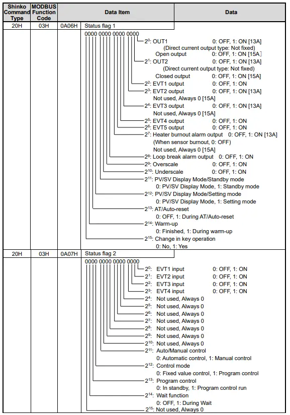
| 20H | 03H | 0A00H | PV (process variable) | Decimal point ignored |
| 20H | 03H | 0A01H | OUT1 MV [13A] Output MV [15A] | Decimal point ignored |
| 20H | 03H | 0A02H | OUT2 MV [13A] | Decimal point ignored |
| 20H | 03H | 0A03H | Current SV | Decimal point ignored |
| 20H | 03H | 0A04H | Remaining time when program runs | Remaining time |
| 20H | 03H | 0A05H | Program running step | Running step (SM) number |
| Shinko Command Type | MODBUSFunction Code | Data Item | Data | ||
| 20H | 03H | 0A08H | CT1 current value [13A] | Decimal point ignored | |
| 20H | 03H | 0A09H | CT2 current value [13A] | Decimal point ignored | |
| 20H | 03H | 0A0AH | Degree of valve opening [15A] | Returns “0.0 to 100.0%” as a Fully Closed/Fully Open position of FBP. (FBP No: Not fixed) | |
Program control command
| Shinko Command Type | MODBUS Function Code | Data Item | Data | |
| 20H/50H | 03H/06H | 1110H | Step 1 SV | Set value (Decimal point ignored.) |
| 20H/50H | 03H/06H | 1111H | Step 1 time | Set value |
| Note: For Step time setting, the smaller unit value of Step time unit (0091H) is calculated, and is converted to hexadecimal numbers. 00:00 to 99:59 (0 to 5999) (e.g) When time unit is set to “Hours:Minutes”: 1 hour 30 minutes→ 90 minutes→ 005AH 15 hours 50 minutes→ 950 minutes→ 03B6H | ||||
| 20H/50H | 03H/06H | 1112H | Step 1 wait value | Set value (Decimal point ignored.) |
| 20H/50H | 03H/06H | 1113H | Step 1 EVT1 alarm value | Set value (Decimal point ignored.) |
| 20H/50H | 03H/06H | 1114H | Step 1 EVT1 high limit alarm value | Set value (Decimal point ignored.) |
| 20H/50H | 03H/06H | 1115H | Step 1 EVT2 alarm value [13A] | Set value (Decimal point ignored.) |
| 20H/50H | 03H/06H | 1116H | Step 1 EVT2 high limit alarm value [13A] | Set value (Decimal point ignored.) |
| 20H/50H | 03H/06H | 1117H | Step 1 EVT3 alarm value [13A] | Set value (Decimal point ignored.) |
| 20H/50H | 03H/06H | 1118H | Step 1 EVT3 high limit alarm value [13A] | Set value (Decimal point ignored.) |
| 20H/50H | 03H/06H | 1119H | Step 1 EVT4 alarm value | Set value (Decimal point ignored.) |
| 20H/50H | 03H/06H | 111AH | Step 1 EVT4 high limit alarm value | Set value (Decimal point ignored.) |
| 20H/50H | 03H/06H | 111BH | Step 1 EVT5 alarm value | Set value (Decimal point ignored.) |
| 20H/50H | 03H/06H | 111CH | Step 1 EVT5 high limit alarm value | Set value (Decimal point ignored.) |
| Note: If independent alarms (such as High/Low limits independent, High/Low limit range independent and High/Low limits with standby independent) are selected in [EVT1 to EVT5 allocation (0060H to 0064H)], Step 1 EVT1 to EVT5 alarm value matches the low limit side, and Step 1 EVT1 to EVT5 high limit alarm value matches the high limit side. | ||||
| One step data comprises values from Step 1 SV to Step 1 EVT5 high limit alarm value. It is possible to set up to Step 15. | ||||
| 20H/50H | 03H/06H | 11F0H | Step 15 SV | Set value (Decimal point ignored.) |
| 20H/50H | 03H/06H | 11F1H | Step 15 time | Set value |
| 20H/50H | 03H/06H | 11F2H | Step 15 wait value | Set value (Decimal point ignored.) |
| 20H/50H | 03H/06H | 11F3H | Step 15 EVT1 alarm value | Set value (Decimal point ignored.) |
| 20H/50H | 03H/06H | 11F4H | Step 15 EVT1 high limit alarm value | Set value (Decimal point ignored.) |
| 20H/50H | 03H/06H | 11F5H | Step 15 EVT2 alarm value [13A] | Set value (Decimal point ignored.) |
| 20H/50H | 03H/06H | 11F6H | Step 15 EVT2 high limit alarm value [13A] | Set value (Decimal point ignored.) |
| 20H/50H | 03H/06H | 11F7H | Step 15 EVT3 alarm value [13A] | Set value (Decimal point ignored.) |
| 20H/50H | 03H/06H | 11F8H | Step 15 EVT3 high limit alarm value [13A] | Set value (Decimal point ignored.) |
| 20H/50H | 03H/06H | 11F9H | Step 15 EVT4 alarm value | Set value (Decimal point ignored.) |
| 20H/50H | 03H/06H | 11FAH | Step 15 EVT4 high limit alarm value | Set value (Decimal point ignored.) |
| 20H/50H | 03H/06H | 11FBH | Step 15 EVT5 alarm value | Set value (Decimal point ignored.) |
| 20H/50H | 03H/06H | 11FCH | Step 15 EVT5 high limit alarm value | Set value (Decimal point ignored.) |
Data Item:
163 digit: 0: Fixed value control, 1: Program control
162 digit: Pattern number (1, fixed) for Program control
161 digit: Step numbers [1 to 15(FH)] for Program control
160 digit: One step data item code for Program control
The set values (from Steps 2 to 15) of the Program control command are common to those of the Set value memory number (from SM2 to SM15). (p.12)
PID zone command
| Shinko Command Type | MODBUS Function Code | Data Item | Data | |
| 20H/50H | 03H/06H | 2010H | PID zone value 1 (Zone 1) | Set value (Decimal point ignored.) |
| 20H/50H | 03H/06H | 2011H | OUT1 proportional band (Zone 1) [13A] Proportional band (Zone 1) [15A] | Set value (Decimal point ignored.) |
| 20H/50H | 03H/06H | 2012H | OUT2 proportional band (Zone 1) [13A] | Set value (Decimal point ignored.) |
| 20H/50H | 03H/06H | 2013H | Integral time (Zone 1) | Set value |
| 20H/50H | 03H/06H | 2014H | Derivative time (Zone 1) | Set value |
| 20H/50H | 03H/06H | 2015H | ARW (Zone 1) | Set value |
| 20H/50H | 03H/06H | 2016H | Manual reset (Zone 1) | Set value (Decimal point ignored.) |
| 20H/50H | 03H/06H | 2017H | OUT1 rate-of-change (Zone 1) [13A] MV rate-of change (Zone 1) [15A] | Set value |
| If “0001H: Used” is selected at [PID zone function (00C1H)], it is possible to set up to 5 zones. [13A]: One zone data comprises from “PID zone value 1” (Zone 1) to “OUT1 rate-of-change” (Zone 1). [15A]: One zone data consists of from “PID zone value 1” (Zone 1) to “MV rate-of-change” (Zone 1). | ||||
| 20H/50H | 03H/06H | 2050H | PID zone value 5 (Zone 5) | Set value (Decimal point ignored.) |
| 20H/50H | 03H/06H | 2051H | OUT1 proportional band (Zone 5) [13A] Proportional band (Zone 5) [15A] | Set value (Decimal point ignored.) |
| 20H/50H | 03H/06H | 2052H | OUT2 proportional band (Zone 5) [13A] | Set value (Decimal point ignored.) |
| 20H/50H | 03H/06H | 2053H | Integral time (Zone 5) | Set value |
| 20H/50H | 03H/06H | 2054H | Derivative time (Zone 5) | Set value |
| 20H/50H | 03H/06H | 2055H | ARW (Zone 5) | Set value |
| 20H/50H | 03H/06H | 2056H | Manual reset (Zone 5) | Set value (Decimal point ignored.) |
| 20H/50H | 03H/06H | 2057H | OUT1 rate-of-change (Zone 5) [13A] MV rate-of-change (Zone 5) [15A] | Set value |
Data item:
163 digit: 0: Fixed value control, 2: PID zone
162 digit: Not used (0, fixed)
161 digit: PID zone number (1 to 5) 160 digit: One zone data item code
The set values (from Zones 1 to 5) of the PID zone command are common to the set values from Zones 1 to 5. (p.12)
Notes on programming monitoring software
How to speed up the scan time
When monitoring multiple units of the controller, set the program so that the requisite minimum pieces of data such as Data item 0A00H (PV), Data item 0A01H {OUT1 MV [13A]/Output MV [15A]}, Data item 0A06H (Status flag 1), can be read.
For other data, set the program so that they can be read only when their set value has changed.
This will speed up the scan time.
How to read the set value changes made by front keypad operation
If any set value is changed by the keypad operation, the controller sets the [0A06H (Status flag 1) 2 15 : Change in key operation] to [1: Yes].
There are 2 methods of reading the set value changes made by front keypad.
(1) Reading method 1
- On the monitoring software side, check that [0A06H (Status flag 1) 2 15: Change in key operation] has been set to 1 (Yes), then read all set values.
- Clear the [0A06H (Status flag 1) 2 15 : Change in key operation], by setting Data item 00F0H (Key operation change flag clearing) to 0001H (Clear all).
If 00F0H (Key operation change flag clearing) is set to 0001H (Clear all) during the setting mode of the controller, Error code 5 (35H, Shinko protocol) or Exception Code 18 (12H, MODBUS protocol) will be returned as a negative acknowledgement. And [Status flag 1 (0A06H) 215 : Change in key operation] cannot be cleared. Set a program so that all set values can be read when a negative acknowledgement is returned. - Read all set values again after acknowledgement is returned.
(2) Reading method 2
- On the monitoring software side, check that [0A06H (Status flag 1) 2 15: Change in key operation] has been set to [1: Yes], then set the [Key operation change flag clearing (00F0H)] to 0001H (Clear all).
- Set the program depending on the acknowledgement or negative acknowledgement as follows.
When acknowledgement is returned:
Consider it as settings completed, and read all set values.
When Error code 5 (35H, Shinko protocol) or Exception code 18 (12H, MODBUS protocol) is returned as a negative acknowledgement:
Consider it as still in setting mode, and read the requisite minimum pieces of data such as PV (0A00H), OUT1 MV [13A] / Output MV [15A] (0A01H), Status flag 1 (0A06H), then return to step 1.
Thus, programs which do not affect the scan time can be created using the methods described above, even if set values on the monitoring software will not be updated until settings are complete.
How to read PID parameters after AT finishes
The controller sets [0A06H (Status flag 1) 2 13 : AT/Auto-reset] to [1: During AT/Auto-reset] while AT is performing.
After AT is finished, PID parameters are updated.
On the monitoring software side, read the parameters such as P, I, D, ARW after checking that [0A06H (Status flag 1) 213 : AT/Auto-reset] has been set to [0: OFF].
Note when sending all set values simultaneously
• When changing alarm types in [Event output EVT1 allocation (0060H)] to [Event output EVT5 allocation (0064H)], alarm value will revert to 0 (zero). First, send the selected alarm type, then send the alarm value.
• When changing input types at [Input type (0030H)], the set values such as SV, OUT1 proportional band [13A] /
Proportional band [15A], Alarm 1 value, etc. will return to the factory default.
First, send the selected input type (0030H), then send other set values.
When responding to the command of Input type selection, it takes approx. 2 seconds due to internal processing.
Therefore, set the Time-out time for communication to 2 seconds or more when executing this command.
When communicating with a PLC
To communicate with a PLC, use a Shinko PLC Interface Unit SIF-600.
No programming is needed for connection.
PLCs corresponding to the SIF-600:
| PLC manufacturer | PLC model | Host link unit model |
| Mitsubishi Electric Corp. | MELSEC Q, QnA series (*) | AJ71UC24, A1SJ71UC24-R2/R4/PRF A1SJ71C24-R2/R4/PRF, QJ71C24 |
| MELSEC FX series (*) | ———– | |
| Omron Corp. | SYSMAC CJ series | CS1W-SCU21-V1 CJ1W-SCU21, CJ1W-SCU41 |
| Keyence Corp. | KV | KV-L20V |
| Yokogawa Electric Corp. | FA-M3 | F3LC11-2N, F3LC11-1F, F3LC12-1F |
| Fuji Electric Co., Ltd. | MICREX-SX series | NP1L-RS1, NP1L-RS2, NP1L-RS3, NP1L-RS4 |
(*) Models with compatible QR/QW communication commands (MC protocol 1C Format 4).
SV Digital Transmission
By connecting to Shinko programmable controllers PCA1 or PCB1 (select ‘SV digital transmission’ in [Communication protocol]), the Step SV can be received from programmable controllers.
8.1 Wiring
RS-232C (only for PCA1):
Connect TX (PCA1) to RX (ACD/R-13A,
ACD/R-15A), RX (PCA1) to TX (ACD/R-13A,
ACD/R-15A) and COM (PCA1) to SG (ACD/R-13A,
ACD/R-15A) terminal.
The following shows connection example between the PCA1 and ACD/R-13A, ACD/R-15A. (Fig. 8.1-1)
RS-485:
For the PCA1, connect YA(-) to YA(-), YB(+) to YB(+),COM to SG terminal respectively.
For the PCB1, connect YA(-) to YA(-), YB(+) to YB(+),SG to SG terminal respectively.
Up to 31 units of the ACD/R-13A or ACD/R-15A can be connected.
The following shows a connection example of PCB1 and ACD/R-13A, ACD/R-15A. (Fig. 8.1-2) 
8.2 Setting Method of Programmable Controllers (PCA1 or PCB1) and ACD/R-13A, ACD/R-15A
(1) Setting the PCA1 or PCB1
Select ‘SV digital transmission’ in [Communication protocol].
(2) Setting the ACD/R-13A, ACD/R-15A
Check the following in the Communication group. Refer to “3. Setting Communication Parameters”. (p.3)
- Shinko protocol has been selected in [Communication protocol].
- Communication speed of the ACD/R-13A or ACD/R-15A is equal to that of the PCA1 or PCB1 (9600 or 19200 bps).
(3) Starting SV digital transmission
Enter the program set values on the PCA1 or PCB1.
If the program is executed by pressing the RUN Key, the step SV of the PCA1 or PCB1 will be sent to the ACD/R-13A, ACD/R-15A.
If SVTC bias value is set, SV adds SVTC bias value to the step SV (received from PCA1 or PCB1 via SVTC command).
During program standby, 0 (zero) will be sent to the ACD/R-13A, ACD/R-15A.
Specifications
| Cable length | RS-232C: 10 m (Max.),RS-485: 1.2 km (Max.) Cable resistance: Within 50 (Terminators are not necessary, but if used, use 120 minimum on both sides.) | |||
| Communication line | EIA RS-232C, EIA RS-485 | |||
| Communication method | Half-duplex communication | |||
| Communication speed | 9600/19200/38400 bps (Selectable by keypad) (Factory default: 9600 bps) | |||
| Synchronization method | Start-stop synchronization | |||
| Code form | ASCII, Binary | |||
| Data bit/Parity | 7, 8/Even, Odd, No parity (Selectable by keypad) (Factory default: 7/Even) | |||
| Stop bit | 1, 2 (Selectable by keypad) (Factory default: 1) | |||
| Communication protocol | Shinko protocol / MODBUS ASCII / MODBUS RTU (Selectable by keypad) (Factory default: Shinko protocol) | |||
| Data format | Communication protocol | Shinko protocol | MODBUS ASCII | MODBUS RTU |
| Start bit | 1 | 1 | 1 | |
| Data bit | 7 | 7 (8) Selectable | 8 | |
| Parity | Even | Even (No parity, Odd) Selectable | No parity (Even, Odd) Selectable | |
| Stop bit | 1 | 1 (2) Selectable | 1 (2) Selectable | |
| Number of connectable units | RS-232C: 1 unit, RS-485: Max 31 units to 1 host computer | |||
| Error correction | Command request repeat system | |||
| Error detection | Parity, checksum (Shinko protocol), LRC (MODBUS ASCII), CRC-16 (MODBUS RTU) | |||
| Digital external setting | By connecting to Shinko programmable controllers PCA1 or PCB1 (select ‘SV digital transmission’ in [Communication protocol]), the step SV can be received from programmable controllers. | |||
Troubleshooting
Check that power is being supplied to the master and slave that customers use. If communication failure still occurs, check the following
| Problem | Possible Cause | Solution |
| Communication failure | Communication cable is not securely connected, or is disconnected/defective. | Check the communication cable and connector. |
| Incorrect wiring of the communication cable and/or connector | Check the communication cable and connector. Refer to Section ‘2. Wiring’ (pp. 1, 2). | |
| Imperfect contact between the communication cable and the connector, or between the communication connector and instrument port | Check the communication cable and connector. | |
| Communication speed of the slave does not match that of the master. | Set the same communication speed on the master and the slave. Refer to Section ‘3. Setting Communication Parameters’ (p. 3). | |
| The data bit, parity and stop bit of the master do not correspond to those of the slave. | Set the same data bit, parity and stop bit on the master and the slave. Refer to Section ‘3. Setting Communication Parameters’ (p. 3). | |
| The instrument number (address) of the slave does not correspond to that of the command. | Check the instrument number (address) of the slave and the command. Refer to Section ‘3. Setting Communication Parameters’ (p. 3). | |
| The instrument numbers (addresses) are duplicated in multiple slaves. | Check that each slave has a different instrument number (address). Refer to Section ‘3. Setting Communication Parameters’ (p. 3). | |
| Make sure that the program is appropriate for the transmission timing. | Check the program. Refer to Section ‘4. Communication Procedure’ (p. 4). | |
| Although communication is occurring, the response is negative acknowledgement. | A non-existent command code has been sent. | Check the command code. |
| The Setting command data exceeds the setting range of the slave. | Check the setting range of the slave. | |
| The controller cannot be set when functions such as AT are performing. | Check the slave status. | |
| The controller is in front keypad operation setting mode. | Return the controller to RUN mode. |
For all other malfunctions, please contact our main office or dealers.
![]() SHINKO TECHNOS CO., LTD.
SHINKO TECHNOS CO., LTD.
OVERSEAS DIVISION
Head Office : 2-5-1, Senbahigashi, Minoo, Osaka, Japan
URL: http://www.shinko-technos.co.jp/e/
E-mail: overseas@shinko-technos.co.jp
Tel :+81-72-727-6100
Fax: +81-72-727-7006
Documents / Resources
 | Shinko ACD/R-13A Three Position Temperature Controllers [pdf] Instruction Manual ACD R-13A Three Position Temperature Controllers, ACD R-13A, Three Position Temperature Controllers, Temperature Controllers |


