![]() MR60FDA1
MR60FDA1
60GHz mmWave Sensor
– Fall Detection Module Pro
User Manual
Overview
The MR60FDA1 radar module is a radar module that uses 60G millimeter wave radar technology for human movement and posture sensing, and thus for fall detection. The module is based on the FMCW radar system and enables the wireless sensing of the status of people in a specific location.
This radar module has the following operating characteristics.
- Implementing the function of detecting the position of people and counting their numbers.
- Limits detection to persons with biological characteristics (moving or stationary) and eliminates interference from other inanimate objects in the environment.
- This module effectively eliminates interference from non-living objects and also enables the detection of non-living moving objects.
- Product support for secondary development, adapting to a wide range of scenario applications.
- Universal UART communication interface, providing a common protocol
- 4 groups of I\O are reserved for user-defined input and output, or simple interface simulation
- The output power is low, with no harm to the human body.
- This module is not affected by temperature, light, dust, and other factors, high sensitivity, and a wide range of applications.
Electrical characteristics and parameters
2.1 Detection angle and distance
| Content | Minimum | Typical | Maximum | Units |
| MR6OFDA1 | ||||
| The radius of movement of people detection [1] | – | 6 | meter | |
| Fall monitoring radius [2] | – | 3. | meter | |
| Radar detection angle (horizontal) | – | 100 | – | degree |
| Radar detection angle (pitch) | – | 100 | – | degree |
Note: [1][2] Radar hang height 2.8 m, the radius of radar projection.
2.2. Electrical characteristics
| Content | Minimum | Typical | Maximum | Units |
| Operating voltage (VCC) | 5. | 5.0 | 6 | V |
| Operating current (ICC) | 90 | 93 | 100 | mA |
| Operating temperature (TOP) | -20 | – | +60 | °C |
| Storage temperature (TST) | -40 | – | +80 | °C |
2. 3. RF performance
| Parameters | ||||
| Operating frequency (X) | 58 | – | 64. | GHz |
| Transmitted power (Pout) | – | – | 6 | dBm |
Module dimensions and pin description
3.1 Module size package

3. 2. Pin description
| Interface | Pins | Description | Typical | Description |
| Interface 1 | 1 | 5V | 5.0V | Power supply input positive |
| 2 | GND | Ground | ||
| 3 | RX | Serial port reception | ||
| 4 | TX | Serial port transfer | ||
| 5 | 51 | 3.3V/OV | ||
| 6 | S2 | 3.3V/OV |
| Interface 2 | 1 | 3V3 | 3.3V | Output power |
| 2 | GND | Ground | ||
| 3 | SL | Reserved | ||
| 4 | SD | Reserved | ||
| 5 | GP1 | Spare expansion pins | ||
| 6 | GP2 | Spare expansion pins | ||
| 7 | GP3 | Spare expansion pins | ||
| 8 | GP4 | Spare expansion pins |
3.2 Using the wiring diagram

Main working properties
4.1 Radar module operating range
The radar module beam coverage is shown. The radar coverage is a threedimensional sector of 100° horizontally and 100° tilted.
Due to the characteristics of the radar beam, the radar acts farther in the direction normal to the antenna face, but the distance away from the antenna normal becomes shorter.
When the radar is mounted on top or at an angle, the radar range will be reduced due to the radar beam range and the effective radiation space, which needs to be taken into account when using the radar.
4.2. main functions and performance
a. Fall detection function
a) Detection distance.
i. ≤ 2 m // radius of radar projection when installed on top
ii. ≤4m // tilt installation, radar projection distance
b) Accuracy rate: ≥90%
b. Presence awareness function
a) Detection distance: ≤3m
//Projection radius
b) Accuracy rate: ≥ 90%
How the radar works and how it is installed
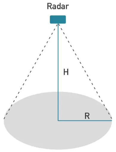
5.1. vertical mounting mode
The radar is mounted on the roof and is directed vertically downwards.
The radar is installed at a height of H = 2.4 m to 3 m; the radius of the radar beam coverage area is R. Within the radar projection area, the projection area is considered to be further divided into a fall detection area, a presence detection area and a motion-triggered detection area, which is shown in the diagram below.

(a) Radar projection schematic
(b) Schematic diagram of beam splitting
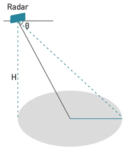
5.2. Tilt mounting mode
Some applications require the radar to be mounted at an angle, e.g. in the corner of a wall.
For this type of installation, a gyroscope sensor is considered to be located at home on the radar for radar tilt measurement, which in turn assists the radar with angle correction.
5.3. Horizontal mounting mode
Given the current number of channels in the radar chip, the fall check function in horizontal mounting mode is not considered for the time being.
Typical applications
A. The product is suitable for small area scenarios such as bathrooms, toilets, and bedrooms.
B. The product is suitable for overhead installation and tilt installation mode.
C. The product is suitable for single/twin situations.
D. The product needs to be combined with the application scenario to eliminate interfering movements.
Documents / Resources
 | seed studio MR60FDA1 Fall Detection Radar Module [pdf] User Manual MR60FDA1, Fall Detection Radar Module, Detection Radar Module, Radar Module, MR60FDA1, Module |


