scs sentinel MVE0116 Channel Remote Control Compatible

SAFETY INSTRUCTIONS
WARNING: Important safety instructions. It is essential to follow these instructions for reasons of personal safety, as incorrect installation may result in serious injury. Keep these instructions in a safe place. If installation is carried out by a third party, this manual must be given to the end user. The end user must also be trained in the safe use of the appliance in accordance with the instructions in this manual.
INFORMATION
SCS SENTINEL certifies that its motorised operators comply with the standards and safety regulations for motorised gate operators (EN 60335-2-103). The use of this product outside the specified conditions or the use of components or accessories not recommended by SCS SENTINEL may compromise the safety of property and persons, and is therefore prohibited. SCS SENTINEL accepts no liability for any damage resulting from failure to comply with the instructions provided in this manual.
BEFORE INSTALLING
- This product is only designed for the automation of a swing gate for “residential” use.
- Installation requires qualified staff with mechanical and electrical skills.
- Before installing the motorised device, check that the driven part is in good mechanical condition, properly balanced and opens and closes correctly.
- Make sure that the temperature range indicated on the motorised system is suitable for the installation’s location.
PLEASE NOTE: The motorised system cannot be used with a driven part incorporating a side gate.
ELECTRICAL INSTALLATION
CAUTION: The power supply installation must comply with current standards in the country where the product is installed (NFC 15-100 for France) and be carried out by qualified staff. The mains supply must be protected against overload by a suitable trip switch and an earth leakage circuit breaker. A means of disconnecting all the poles of the power supply network must be provided. This device must be connected directly to the supply terminals and have a contact separation distance on all poles to ensure complete disconnection in accordance with the installation rules. If the power cable is damaged, it must be replaced by the manufacturer, its after-sales service or similarly qualified persons in order to avoid a hazard.
 INSTALLING THE MOTORISED SYSTEM
CAUTION: The motorised device must be disconnected from its power source during installation.
WARNING: Make sure that in the installation environment (gate and fixed parts), the zones at risk are avoided or at least signposted (see “Potential risks” section after these instructions).
Ensure that crushing caused by the opening movement of the driven part is avoided between the driven part and the surrounding fixed parts.
WARNING: Activation of the manual disconnection device may cause uncontrolled movement of the driven part due to mechanical failure or loss of balance. If a fixed control device is installed (keypad, key selector, etc.), it must be installed 1.5 m above the ground, away from moving parts but always within sight of the gate.
In accordance with European standards EN 12453 and EN 13241-1 applicable to industrial, commercial and residential motorised door and gate installations, and depending on the installation environment, accessories not included in this kit (photocells and flashing light) may be required.
- If the gate is to operate in automatic closing mode, or if it is to be opened remotely without a direct view of the gate, photocells must be installed without fail.
- If your gate closes automatically, or if it opens onto the public highway, it may be compulsory to install a flashing light, depending on the regulations in the country where the motorised device is installed.
- It is the installer’s responsibility to ensure that the installation is compliant.
- After installation, make sure that the mechanism is properly adjusted and that the protection system and any manual disconnection devices function properly. Permanently attach the label concerning the manual disconnection device to the operating element of this device.
![]() USING THE MOTORISED SYSTEM
USING THE MOTORISED SYSTEM
PLEASE NOTE: This appliance may be used by children at least 8 years old and by people with reduced physical, sensory or mental capabilities or without experience or knowledge, if they are properly supervised or instructed in the safe use of the appliance, and if the risks involved have been understood.
- Children should not play with the appliance.
- The user’s cleaning and maintenance must not be carried out by unsupervised children.
- Do not allow children to play with the unit or its controls. Keep remote control units out of the reach of children.
WARNING: The user must supervise the gate during operation and keep people away until the gate is fully opened or closed. Do not deliberately hinder gate movement.
MAINTENANCE AND UPKEEP OF THE MOTORISED DEVICE
CAUTION:The motorised device must be disconnected from its power source during cleaning, maintenance and parts replacement.
Check the installation frequently for poor balancing or signs of wear or damage to cables, springs and mounting. Do not use the appliance if any repairs or adjustments are required. Only original parts should be used to replace or repair the motorised system. For further information, see section
Maintenance
REMOTE CONTROLS
CAUTION: Do not swallow the battery (risk of chemical burns).
® This product contains a button cell battery. If swallowed, the button cell battery can cause severe internal burns in only 2 hours and may cause death. Keep new and used batteries out of the reach of children. If the battery compartment does not close securely, stop using the product and keep it out of the reach of children. If you suspect a battery or other part has been swallowed or inserted into any part of the body, seek medical advice immediately. Do not clean the remote control with abrasive or corrosive substances.
Just use a soft cloth. Do not allow children to play with the product or its packaging. When replacing batteries, ensure they have the same characteristics as the ones supplied with the product. If the device is not being used for a prolonged period, remove the batteries unless the system is intended for emergency situations. Do not expose the batteries to excessive heat or throw them in a fire.
Potential risks 
Risk 1 : Shock and crushing Prevention :
- Obstacle detection by motor.
- Use of photocells.

Risk 2 : Hand crushing
Prevention :
- Leave a minimum distance of 10 cm between the leaf and the pillar/wall.
- Notch the corner of the pillar without weakening it.

Risk 3 : Imprisonment and crushing
Prevention :
- Obstacle detection by the motor.
- Leave a minimum distance of 50 cm between the motor arm and the wall (or other fixed part).

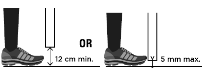
Risk 4 : Crushing of the feet
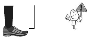
Prevention :
- To avoid a danger zone for feet, leave a minimum distance of 12 cm or a maximum of 5 mm between the bottom of the leaves and the floor.
DESCRIPTION
Content 
Dimensions 
WIRING/ INSTALLING
Standard installation 
Dimension chart
Comply with the measures shown on the chart for proper installation_ Adjust the gate structure to fit it for best automation, if necessary.
Before proceeding with the installation, be sure that gate moves freely and that
- Hinges are properly positioned and greased.
- No obstacles in the moving area.
- No frictions between two gate leafs or with the ground while moving
inside opening – installation with closed gate
Outside opening – installing with open gate (max 90°)
Warning ! With outside opening. it is imperative to install a blinker on pillar for security reasons.
For an external opening, it will be necessary to manufacture a metal part in order to offset the motors. it is then IMPERATIVE to respect the dimensions of installation indicated in the table.

Emergency release
- In case of power failure or to program your automatic gate, you can manually unlock the engines:
- Under the gate. Insert the hex wrench for unlocking and then turn anti-clockwise 180 degrees. You can now open the gate by hand.
- To lock again the engine, insert the hex wrench for locking and then turn clockwise 180 degrees.

- Permanently attach the label for the manual disconnection device to the operating element of this device.
Motor fixing
Before placing the arm on the gate, unlock the arm (C3) and take out the tub from the cylinder. Then, retract the tube by 3 cm (this ensures that the gate is locked when closed)
TIP
If you have problems unlocking your motor, you can use a battery. Simply connect the white and yellow motor wires, one way or the other following the polarity to operate the motors.


- Fix the first bracket to the pillar. Position the automation in the bracket, then place the screw and nut.
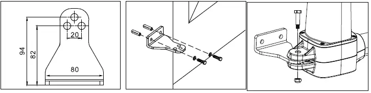
- Assemble the second bracket with the other side of the automation and screw the bracket to the closed gate.

Make sure arms are fixed in horizontal position especially in those positions:
- Gate in« CLOSE» position
- Gate in« OPEN» position
- Gate at« 45° angle» position
Prior to weld the bracket on the gate leaf (if necessary), cover the gate opener to prevent damages from sparks.
Wiring diagram


Installing
Prepare all the wires of the accessories beforehand and connect the wires to the gear motors and accessories on the PCB as shown in Figure 1. All of the wiring connections of the accessories are not requested to distinguish the positive(+) and the negative(-) polarity.
Control box
BEFORE INSTALLATION
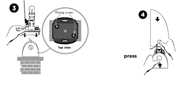
Decide the installation position of control box first, it is suggested to be installed near the gate and should be protected from possible damage.
Be aware of the motor cable length before deciding the installation position of the control box.
PRE-INSTALLATION
- Remove the cover by unscrewing the four screws on the cover. See Figure 1(1).
- Use a screwdriver to puncture the holes beneath the bottom of the control box. See Figure 1 (2).
- Fix and secure your electronic box on the wall.
- Connect the wires of the various devices to be connected to the PCB board (devices described on the following pages)
- Cables should only pass through the bottom of the enclosure through the pre-drilled holes. Seal the holes of your cable passages (cable glands, silicone).
- Close the box by tightening the 4 screws. (See Figure 1 (3))

Motor
MOTOR – WIRE CONNECTION 
Note: Ensure that the white and yellow wires are stripped by 5 mm.
Avoid tension in the cable during open and close phase.
NOTE, FOR GATES OPENED OUTWARD: M1 Motor: Connect the motor wire (Yellow -) to the terminals Mol +, and (White +) to the terminals Mol-. (motor opening in first)
M2 Motor: Connect the motor wire (Yellow -) to the terminals Mo2 +, and (White +) to the terminals Mo2 -.
M1 MOTOR CONNECTION (first opening motor)

MZ MOTOR CONNECTION (second opening motor)

Electric Lock (option)
Connect the two wires from the electric lock (24V) to the terminal Lo + and Lo- on the PCB.
Wiring to 230V power supply 
Photocells (option – AAM0036)
The photocells are safety devices for control automatic gates. Consist of one transmitter and one receiver based in waterproof covers; it is triggered while breaking the path of the beams. If an obstacle is detected, the gate stops and opens again slightly allowing the obstacle to be released safely. 
Blinker (option – AAM0111)
Remove any packaging before connecting. 
SETTING/USING
D1- Single/double gate setting (dip switch 1) 
Switch settings: «on» right position, «off» left position.
- DIP SWITCH 1 D/S set :
- ON = double gate operation
- OFF= single gate operation (connection on MOT 1)
- D2- Dip switch 2 et 3
- Switch 2 and 3 are not used.
- D3- Gate auto-close adjustment (dip switch 4)
DIP SWITCH 
- «ON»: Active automatic closing in 30 seconds. Simultaneously pressing the two remotes keys (opened or closed gate) will turn OFF the automatic mode (the blinker will flash 3 times as confirmation).
- Repeat the operation to turn ON the automatic mode (the blinker will flash 3 times as confirmation).
Note: in case of automatic closing, photocells are required.
- «OFF»: Automatic closing OFF (caution it will still be possible to turn ON with the remote)
Photocell adjustment (dip switch 5)
DIP SWITCH 5 :
- ON : Photocells ON. When the photocells detect an obstacle while the gate is closing, the gate stops and opens during 2 seconds.
- If the gate auto-close is adjusted, and the photocells detect an obstacle when the gate is totally opened, then
- the closing time will be reseted.
- OFF: Photocells OFF. The photocells will no longer have any influence on gate operation.
- D5- Dephasing of the leaves (dip switch 6)
DIP SWITCH 6 :
- ON : Dephasing in closing/ opening of 8 seconds.
- OFF: Dephasing in closing/ opening of 5 seconds.
Slowing down
- Operating speeds are not adjustable.
LED indication

LED 1 indicator: radio frequency:
- LED1 will be on when remote controls are activated.
LED 2 System learning:
- LED 2 blinks twice per second during normal operation and once per second during learning. Static LED2 means the learning process can be done over and over again
LED 3 Photocells:
- LED 3 will be on when photocells are not aligned or when there’s an obstacle in between.
LED4 start:
- LED 4 will be on if the switch of the transmitter, key selector, or the push button is activated.
Remote controls learning process
Add the remote controls to the motorisation :
- Press the ‘RF-Learn’ button until LED1 lights up.
- Then press the button at the left of the remote control. LED1 flashes twice and remains lit for 10 seconds, then goes out. The remote control has been memorised.
- Deleting remote controls from the motorisation :
- Hold down the RF button until LED1 goes out.
System learning process for double leaf gate
- Switch n°1 must be in the ON position.
- Unlock the motors, position the 2 leaves at mid-travel, then re-lock the motors.
- On the electronic board, hold down the SYS-learn button until LED2 flashes once a second (instead of twice a second or steady), then release.
- Press the button on the left of the remote control.
- The learning process should be as follows:
- The leaf connected to the MOTZ output closes completely. (If it opens, press the left-hand button on the remote control again to interrupt the learning procedure. LED2 remains permanently lit. Reverse the motor polarity and start again from step 1).
- The leaf connected to the MOT1 output closes completely. (If it opens, press left again on the remote control to interrupt the learning procedure. LED2 remains permanently lit. Reverse the motor polarity and start again from step 1 ).
- The leaf connected to output MOT1 reopens completely.
- The leaf connected to output MOTZ reopens fully.
- The leaf connected to the MOTZ output closes completely.
- The leaf connected to output MOT1 closes completely.
After step 5, the learning process for your gate is complete. You can use it with the remote control:
total opening of the 2 leaves pedestrian opening (1 single leaf)
If the learning process is not complete, LED2 will remain lit. Check the connections and repeat the operation.
D10- System learning process for single leaf gate
- Switch No. 1 must be in the OFF position.
- The motor must be connected to the MOTi output.
- Unlock the motor, position the leaf at mid-travel, then relock the motor.
- On the electronic board, hold down the SYS-learn button until LED2 flashes once a second (instead of twice a second or steady), then release.
- Press the button on the right of the remote control.
- The learning process should be as follows:
- The leaf closes completely. (If it opens, press the right-hand button on the remote control again to interrupt the learning procedure. LED2 remains permanently lit. Reverse the polarity of the motor and start again from step 3).
- The leaf closes fully. leaf fully opens
Obstacle detection
- If an obstacle is detected while the gate is opening: the gate stops.
- If an obstacle is detected while the gate is closing: the gate stops, reopens and closes again.
When the gate reaches the closing stop, it reopens to clear any obstacle.
TECHNICAL FEATURE


MAINTENANCE
Motor
Conduct the following operations at least every 6 months. If in high intensity of use, shorten the period in between.
Disconnect the power supply:
- Clean and lubricate the screws, the pins, and the hinge with grease.
- Check the fastening points are properly tightened.
- Make the wire connection are in good condition.
Connect the power supply:
- Check the power adjustments.
- Check the function of the manual release.
- Check the function of photocells or other safety device.
Remote control

TECHNICAL ASSISTANCE
Troubleshooting

| The leaves suddenly stop during moving The leaves does not move or only move toward one direction |
|
| The master gate closes to the end first and the slave gate stops, which the opening or closing sequence is not being operated properly |
|
| The gear motors does not run and the relay is noisy when operating the gate opening and closing | Check the condition fuse. |
| No remote control connection |
|
| Remove remote controls from the operator | Hold down the RF button until LE01 flashes. |
Online assistance
 Any question?
For an individual answer, use our on line chat on our website www.scs-sentinel.com
WARRANTY
 SCS Sentinel grants to this product a warranty period, beyond the legal time, as a sign of quality and reliability.
The invoice will be required as proof of purchase date. Please keep it during the warranty period. Carefully keep the barcode and the proof of purchase, that will be necessary to claim warranty..
Are never covered by our warranty:
- Damage resulting from the consequences of a bad installation (bad wiring, reverse polarity .
- Damage resulting from improper use of the device (use in contradiction with the manual) or its modification.
- Damage resulting from the consequences of the use of components not from SGS SENTINEL.
- Damage due to lack of maintenance, physical shock.
- Damage due to weather: hail, lightning, strong wind etc ..
- Returns made without a copy of the invoice or receipt.
WARNINGS
 Don’t throw batteries or out of order products with the household waste (garbage). The dangerous A substances that they are likely to include may harm health or the environment. Make your retailer take back these products or use the selective collect of garbage proposed by your city.
DECLARATION OF CONFORMITY
SGS Sentinel hereby declares that this product is in compliance with the essential requirements and other relevant provisions of Directive 2014/53/EU and Directive 2006/42/EC. The Declaration of Conformity can be found at: www.scs-sentinel.com/downloads
Toutes les infos sur :
www.scs-sentinel.com 
110, rue Pierre-Gilles de Gennes 49300 Chalet – France
Documents / Resources
 | scs sentinel MVE0116 Channel Remote Control Compatible [pdf] Instructions 7503, 17289841040148, MVE0116 Channel Remote Control Compatible, MVE0116, Channel Remote Control Compatible, Remote Control Compatible, Control Compatible, Compatible |


