SAMSUNG MIM-B14 External Controller
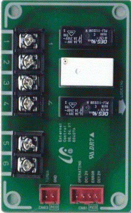
Specifications
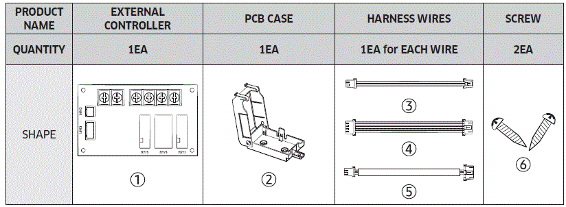
- Product Name: External Controller
- Quantity: 1EA
- Parts Included:
- PCB Case: 1EA
- Harness Wires: 1EA for EACH WIRE
- Screw: 2EA
Parts
Installation
- Fix PCB case(2) inside the indoor unit control box or at an appropriate position with screws (6).
- After fixing PCB cases, attach the external controller PCB. (See the following figure, Assembly Drawing)
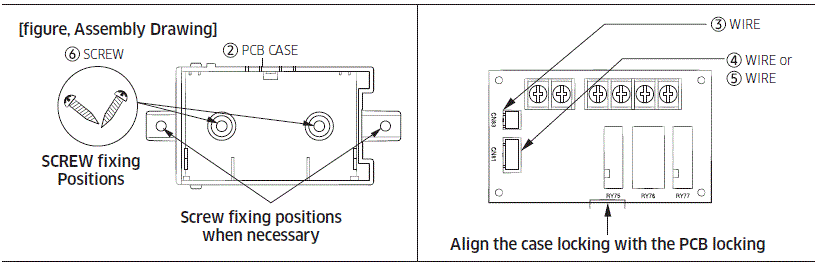
- Connect 2 pin wire (3) between the external controller PCB CN83 and indoor unit PCB EXT_CTRL connector(CN83).
- Connect 4 pin wire (4) between the external controller PCB CN81 and indoor unit PCB COMP/ERROR connector(CN81).
- Connect 4 pin wire (5) between the external controller PCB CN81 and indoor unit PCB R32 CHECK LAMP/EXTERNAL ALARM connector(YELLOW). ※ Refer to Indoor Unit manual.
Installation option setting of indoor unit
Indoor unit with DIP S/W
Operation Specification according to Indoor Unit PCB installation option Set up
| WIRE NO. | OUTPUT STATE | |
| K11 OFF | K11 & K12 OFF | |
| 1,2 | Error Check | |
| 3,4 | COMP. Check | Operating Check |
| 5,6 | Signal Input (TIMER) | |
Indoor unit without DIP S/W
| Purpose | 5, 6 INPUT | 3, 4 OUTPUT | 1, 2 OUTPUT |
| Turn on/off the indoor unit via external contact control | DRY CONTACT | THERMO ON/OFF or OPERATION ON/OFF | ERROR STATUS (Normal Close) |
| Control external heater | External heater’s Switch | ||
| Turn on/off the indoor unit via external contact control and control external heater (1*) | DRY CONTACT | External heater’s Switch |
(*1) When the purpose is to use as external heater’s on/off signal, monitoring signal for external contact control will not be outputted.
Circuit diagram
Circuit diagram of external controller’s output
For turning on/off the indoor unit via external contact control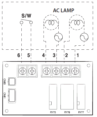
For controlling external heater (On/Off)
Circuit diagram for using external heater for the indoor units without hot water coil terminal 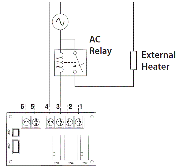
- Detailed method about Installation option establishment refers to Indoor Unit manual. (External contact control setting: Refer to SGE14, SGE15 of 02 Series installation option External heater control setting: Refer to SEG15 of 02 Series Installation Option and SEG18 of 05 Series installation option).
- Dry contact(no power source contact) must be be connected to the input terminal 5,6.
- When MIM-B14 is used for controlling external heater, its contact should not be connected directly to the load.(Only use as switch as shown in above diagram.)
 This marking on the product, accessories or literature indicates that the product and its electronic accessories (e.g. charger, headset, USB cable) should not be disposed of with other household waste.
For correct disposal of this product, please visit http://www.samsung.com/weee.pdf
This product is India RoHS compliant
Frequently Asked Questions
- Q: How do I dispose of the product and its electronic accessories?
- A: This product and its electronic accessories should not be disposed of with other household waste. For correct disposal,please visit www.samsung.com/weee.pdf.
- Q: What does the India RoHS compliance mean for this product?
- A: The product is India RoHS compliant, indicating that it meets the Restriction of Hazardous Substances regulations in India.
- Q: Can I recycle this product and its accessories?
- A: Yes, this product, its accessories, batteries, and cords are recyclable. Find collection points at www.quefairedemesdechets.fr.
Documents / Resources
 | SAMSUNG MIM-B14 External Controller [pdf] Installation Guide MIM-B14, MIM-B14, MIM-B14 External Controller, External Controller, Controller |