1. Введение
The FNIRSI DST-210 is a compact and versatile 3-in-1 handheld device designed for electronic testing and measurement. It integrates the functions of a digital oscilloscope, a true RMS multimeter, and a signal generator into a single portable unit. This manual provides detailed instructions to help you effectively use and maintain your device.
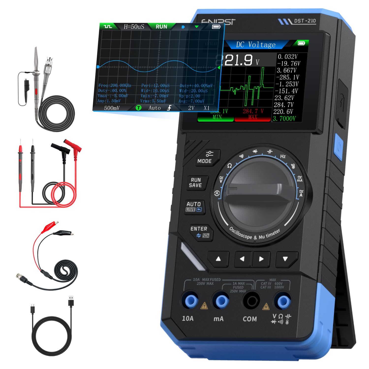
Figure 1: FNIRSI DST-210 3-in-1 Handheld Device
2. Продукт закончилсяview
2.1 Основные характеристики
- 3-в-1 Функциональность: Combines a digital oscilloscope, a true RMS multimeter, and a signal generator.
- Отображать: 2.8-inch TFT color LCD for clear data visualization.
- Осциллограф: 10MHz analog bandwidth, 48MSa/s real-time sampling rate, supports Auto/Normal/Single trigger modes, waveform image saving and display.
- Мультиметр: 19999-count true RMS measurement for DC/AC voltage, DC/AC current, resistance, capacitance, frequency, temperature, diode, and continuity. Features data hold, record mode with graphical display, and LIVE function for voltagобнаружение присутствия.
- Генератор сигналов: Outputs 13 types of waveforms (Sine, Square, Sawtooth, Half-wave, Full-wave, Step, Reverse Step, Index Up/Down, DC, Multi-audio, Sink Pulse, Lorentz Wave) with adjustable frequency (0-50KHz), amplitude (0.1-3.0V), and duty cycle (0-100%).
- Портативность: Compact design with an integrated stand, powered by a 3000mAh rechargeable lithium battery providing up to 10 hours of continuous use. Type-C charging supported.
2.2 Содержимое упаковки
Проверьте наличие всех предметов в упаковке:
- FNIRSI DST-210 Main Unit
- P6100 Высокая громкостьtage Зонд
- Тестовые провода (красные и черные)
- Аллигаторные зажимы
- Зарядный кабель типа C
- Инструкция по эксплуатации (PDF-версия доступна онлайн)
- Упаковочная коробка

Рисунок 2: Входящие в комплект аксессуары
3. Настройка
3.1 Зарядка устройства
Before initial use, fully charge the DST-210. Connect the provided Type-C charging cable to the device's Type-C port and a compatible USB power adapter (5V/1A). The battery indicator on the display will show charging status.
3.2 Подключение зондов
For accurate measurements, ensure probes are correctly connected:
- Multimeter Measurements: Insert the red test lead into the VΩHzmA or 10A jack (depending on the measurement) and the black test lead into the COM jack.
- Oscilloscope Measurements: Подключите P6100 с высокой громкостьюtage probe to the oscilloscope input jack. Ensure the probe's attenuation setting (e.g., X1 or X10) matches the device's setting for accurate readings.
- Выход генератора сигналов: Connect the output cable to the signal generator output port.

Figure 3: Input Jacks and Controls
4. Инструкция по эксплуатации
4.1 Включение/выключение питания
Чтобы включить или выключить устройство, нажмите и удерживайте кнопку питания (расположенную сбоку).
4.2 Выбор режима
Rotate the central knob to switch between Multimeter, Oscilloscope, and Signal Generator modes. Within each mode, further sub-functions can be selected using the knob or dedicated buttons.

Figure 4: Using the Oscilloscope Function
4.3 Работа мультиметра
In Multimeter mode, the device offers various measurement functions:
- Томtage/Current (DC/AC): Select the appropriate DC V, AC V, DC A, or AC A setting. Connect test leads to the circuit. The device supports a record mode that displays measurement trends graphically, and can store up to 10 sets of data.
- Сопротивление (Ом): Select the resistance function. Connect test leads across the component.
- Емкость (Ф): Select the capacitance function. Connect test leads across the capacitor.
- Частота (Гц): Select the frequency function. Connect test leads to the signal source.
- Диодный Тест: Select the diode function. Connect test leads across the diode to check its forward voltagе падение.
- Тест на непрерывность: Select the continuity function. Connect test leads across a conductor; a beep indicates continuity.
- Температура: Use a K-type thermocouple (not included) connected to the appropriate jacks for temperature measurement.
- LIVE Function: For single-probe voltagобнаружение присутствия.

Рисунок 5: Пример измерения мультиметром.ampле
4.4 Работа осциллографа
In Oscilloscope mode, the device displays waveforms:
- Отображение формы волны: Connect the oscilloscope probe to the circuit. The device automatically adjusts settings for stable waveform display.
- Режимы запуска: Select between Auto, Normal, and Single trigger modes to capture different types of signals.
- Сохранение осциллограммы: Press the 'RUN/SAVE' button to save the current waveform image. Saved images can be reviewредактируется и экспортируется.

Figure 6: Oscilloscope Waveform Display
4.5 Работа генератора сигналов
In Signal Generator mode, the device outputs various waveforms:
- Выбор формы сигнала: Choose from 13 different waveform types using the menu options.
- Регулировка параметров: Отрегулируйте частоту (0-50 кГц). amplitude (0.1-3.0V), and duty cycle (0-100%) as required for your application.

Figure 7: Signal Generator Waveform Selection
4.6 PC Connection and Data Export
The DST-210 can connect to a PC via its Type-C USB port for data management and firmware updates.
- Waveform Screenshots: Long-press the 'RUN/SAVE' button to save waveform screenshots.
- Экспорт данных: Connect the device to a computer to view, save, and export recorded waveform images and data.
- Обновления прошивки: Периодически проверяйте официальный сайт FNIRSI. webДля обновления прошивки и обеспечения оптимальной производительности и доступа к новым функциям посетите соответствующий сайт. Следуйте инструкциям, прилагаемым к пакету обновления прошивки.

Figure 8: PC Connection for Data Management
5. Техническое обслуживание
- Уборка: Для чистки устройства используйте мягкую сухую ткань. Не используйте абразивные чистящие средства или растворители.
- Хранилище: Храните устройство в прохладном, сухом месте, вдали от прямых солнечных лучей и экстремальных температур.
- Уход батареи: Чтобы продлить срок службы аккумулятора, избегайте его частой полной разрядки. Регулярно заряжайте устройство, даже если оно не используется в течение длительного времени.
- Уход за зондом: Inspect test leads and probes for damage before each use. Replace any damaged accessories immediately.
6. Поиск Неисправностей
| Проблема | Возможная причина | Решение |
|---|---|---|
| Устройство не включается. | Разряжена батарея или неисправна кнопка питания. | Charge the device fully. If the issue persists, contact support. |
| Unstable or inaccurate readings in Multimeter mode. | Poor probe connection, incorrect mode selection, or external interference. | Ensure probes are securely connected. Verify the correct measurement mode is selected. Minimize external electrical interference. |
| Oscilloscope waveform is not stable. | Incorrect trigger settings or probe attenuation. | Adjust trigger level and mode. Ensure probe attenuation (X1/X10) matches the device setting. |
| Выходные данные генератора сигналов неверны. | Incorrect waveform type, frequency, amplitude, or duty cycle settings. | Verify all signal generator parameters are set as desired. |
| Не удаётся подключиться к компьютеру или экспортировать данные. | Faulty USB cable, incorrect PC driver, or software issue. | Try a different Type-C cable. Ensure necessary drivers are installed on your PC. Refer to the official webСайт для загрузки программного обеспечения и драйверов. |
7. Технические характеристики
7.1 Параметры осциллографа
| Категория | Спецификация |
|---|---|
| В реальном времени Sampскорость | 48MSa / с |
| Аналоговая полоса пропускания | 10МГц |
| Входное сопротивление | 1МОм |
| Метод соединения | Переменный/постоянный ток |
| Объем измеренияtage Диапазон | 1:1 Probe: ±80Vpp (±40V), 10:1 Probe: ±800Vpp (±400V) |
| Вертикальная чувствительность | 10mV/div ~ 10V/div (at X1) |
| Вертикальное смещение | Adjustable (with indicator) |
| Горизонтальный диапазон временной базы | 50нс ~ 20с |
| Режим триггера | Авто, Нормальный, Одиночный |
| Триггер края | Восходящий/нисходящий край |
| Уровень запуска | Adjustable (with indicator) |
| Заморозка формы волны | Supported (HOLD function) |
| Автоматическое измерение | Max, Min, Average, RMS, Peak-to-Peak, Frequency, Duty Cycle, etc. |
7.2 Параметры мультиметра
| Функция измерения | Диапазон | Точность |
|---|---|---|
| DC Томtage | 1.9999В/19.999В/199.99В/1000В | ±(0.5%+3) |
| том переменного токаtage | 1.9999В/19.999В/199.99В/750В | ±(1.0%+3) |
| Постоянный ток | 19.999 мА/199.99 мА/1.9999 А/9.999 А | ±(1.2%+3) |
| Переменный ток | 19.999 мА/199.99 мА/1.9999 А/9.999 А | ±(1.5%+3) |
| Сопротивление | 19.999MΩ/199.99kΩ/19.999kΩ | ±(2.0%+5) |
| Емкость | 999.9uF/99.99uF/9.999uF/999.9nF/99.99nF, 9.999mF/99.99mF | ±(2.0%+5) |
| Частота | 9.999MHz/999.9kHz/99.99kHz/9.999kHz/999.9Hz/99.99Hz | ±(0.1%+2) |
| Температура | [-55~1300°C] / [-67~2372°F] | ±(2.5%+5) |
| Диод/Прозвонка | Поддерживается | Н/Д |
| Функция прямой трансляции | Поддерживается | Н/Д |
7.3 Параметры генератора сигналов
| Категория | Спецификация |
|---|---|
| Выходные сигналы | 13 видов |
| Частота формы волны | 0 ~ 50KHz |
| Рабочий цикл | 0 ~ 100% (adjustable) |
| Форма волны Ampдолгота | 0.1 ~ 3.0 В |
7.4 Общие характеристики
| Категория | Спецификация |
|---|---|
| Модель продукта | ДСТ-210 |
| Отображать | 2.8-дюймовый цветной TFT-дисплей |
| Подсветка | Яркость регулируется |
| Источник питания | Тип-C (5 В/1 А) |
| Аккумулятор | 3000мАч |
| Поддержка языков | Китайский, английский |
| Размер продукта | Прибл. 177.43 мм x 87 мм x 35 мм |
| Вес продукта | Приблизительно 300 г |
8. Гарантия и поддержка
For any questions, issues, or support needs regarding your FNIRSI DST-210, please contact us through the following methods:
- Сообщение Амазонки: If you purchased the product on Amazon, you can contact us via the Amazon messaging system. Go to your 'Order History', select the relevant order, and click 'Problem with order' or 'Contact Seller'.
- Поддержка по электронной почте: You can also reach our after-sales service center directly via email at support@fnirsi.com. Please include your order number and a detailed description of your issue for faster assistance.
When attaching large photos or videos, email support is recommended due to potential attachment size limits on Amazon's messaging system.
Video 1: Demonstration of FNIRSI DST-210's Multimeter, Oscilloscope, and Signal Generator Functions.