 User Manual Q&A
Answer

Sep 16, 2025 - 01:50 PM
To connect the Digilent PmodAD1 Digital Converter Expansion Module to your host board, follow these steps:
1. **Identify the Pinout:**
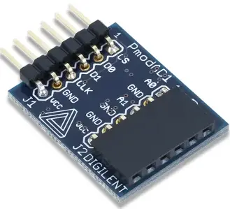
- The PmodAD1 has two headers, J1 and J2, each with different pin configurations.
- Header J1 includes pins for Chip Select (CS), Input Data 1 (D0), Input Data 2 (D1), Serial Clock (SCK), Ground (GND), and Power Supply (VCC).
- Header J2 includes pins for Input Data 1 (A0), Ground (GND), Input Data 2 (A1), Ground (GND), Ground (GND), and Positive Power Supply (VCC).
2. **Power Supply Voltage:**
- Ensure that any external power applied to the PmodAD1 is within the range of 2.35 to 5.25 volts to guarantee proper functionality of all components.
3. **Communication Protocol:**
- The PmodAD1 communicates with the host board using an SPI-like communication protocol.
- The data lines (MOSI and MISO) are designed as Master-In-Slave-Out lines due to the two ADCs on the chip.
- The module provides 12 bits of information to the system board over 16 clock cycles, with the first four bits being leading zeroes and the remaining 12 bits representing the data with the MSB first.
- The first leading zero is clocked out on the falling edge of the Chip Select (CS) signal, and the subsequent bits are clocked out on the falling edge of the Serial Clock (SCK) signal.
4. **Physical Dimensions:**
- The pins on the pin header are spaced 100 mil apart.
- The PCB dimensions are 0.95 inches long parallel to the pins and 0.80 inches long perpendicular to the pin header.
By following these steps and referring to the pinout table provided in the manual, users can successfully connect and interface the Digilent PmodAD1 Digital Converter Expansion Module with their host board for accurate analog-to-digital conversion.


Add New Comment