Hantek DSO2D15

Hantek DSO2D15 Digital Oscilloscope User Manual

Model: DSO2D15 | Brand: Hantek

1. Introdução

This manual provides detailed instructions for the operation, maintenance, and troubleshooting of the Hantek DSO2D15 Digital Oscilloscope. The DSO2D15 is a high-performance, portable 2-channel digital oscilloscope featuring a 150MHz bandwidth, 1GSa/s real-time sampling rate, and an 8Mpts memory depth. It also integrates a 1-channel 25MHz arbitrary waveform generator, making it a versatile tool for various electronic testing and measurement applications.

Hantek DSO2D15 Digital Oscilloscope front view

Figura 1.1: Frente view of the Hantek DSO2D15 Digital Oscilloscope, showing the display, control panel, and input ports.

2. Principais características

The Hantek DSO2D15 is equipped with a range of features designed for precision and versatility in signal analysis:

  • Alto desempenho: 2 channels with 150MHz bandwidth, 1GSa/s real-time sampling rate, and 8Mpts memory depth.
  • Integrated Waveform Generator: Built-in 1-channel 25MHz arbitrary waveform generator supporting various standard and arbitrary waveforms.
  • Multiple Trigger Modes: Features 14 trigger modes, including Edge, Pulse, Video, Slope, Timeout, Window, Pattern, Interval, Undervoltage, UART, LIN, CAN, SPI, and IIC for comprehensive signal capture.
  • Extensive Measurement Capabilities: 32 automatic measurements with statistical analysis (min/max/standard deviation).
  • Análise Avançada: Includes PASS/FAIL functionality, Math operations (Addition, Subtraction, Multiplication, Division, FFT), and serial bus decoding (RS232/UART, I2C, SPI, CAN, LIN).
  • Armazenamento de dados: Supports saving settings, waveforms, reference waveforms, CSV data, and images. USB one-click screenshot function.
  • Exibição amigável: 7-inch TFT LCD display with 800x480 pixel resolution.
  • Conectividade: USB Host and USB Device interfaces for data transfer and remote control.
Key parameters and features of Hantek DSO2D15 oscilloscope

Figure 2.1: Visual summary of the Hantek DSO2D15's key parameters and features, including 2 channels, 150 MHz bandwidth, signal generator, 14 triggering modes, 1GSa/s sampling rate, 8M storage depth, and 32 types of automatic measurement.

3. Configuração

3.1 Desembalagem e Inspeção

Carefully unpack the oscilloscope and all accessories. Inspect all items for any signs of damage during transit. If any damage is found, contact your dealer immediately.

3.2 Conexão de Energia

  1. Ensure the power switch on the oscilloscope is in the OFF position.
  2. Connect the provided power cable to the power input port on the rear of the oscilloscope.
  3. Plug the other end of the power cable into a grounded AC power outlet. The oscilloscope supports 100-240VAC RMS, 45-440Hz.

3.3 Conexão e Compensação da Sonda

  1. Connect the BNC end of the oscilloscope probe to one of the input channels (CH1 or CH2) on the front panel.
  2. Attach the probe tip to the probe compensator output terminal (typically a square wave output) on the front panel.
  3. Turn on the oscilloscope.
  4. Adjust the probe compensation until a flat-top square wave is displayed on the screen. This ensures accurate measurements.

4. Instruções de operação

4.1 Painel de controle sobreview

The front panel of the DSO2D15 is intuitively designed for ease of use. It consists of the display, function buttons (F0-F6), menu buttons, vertical controls (VOLTS/DIV, POSITION), horizontal controls (SEC/DIV, POSITION), trigger controls, and input channels.

Control buttons and ports on the Hantek DSO2D15 oscilloscope

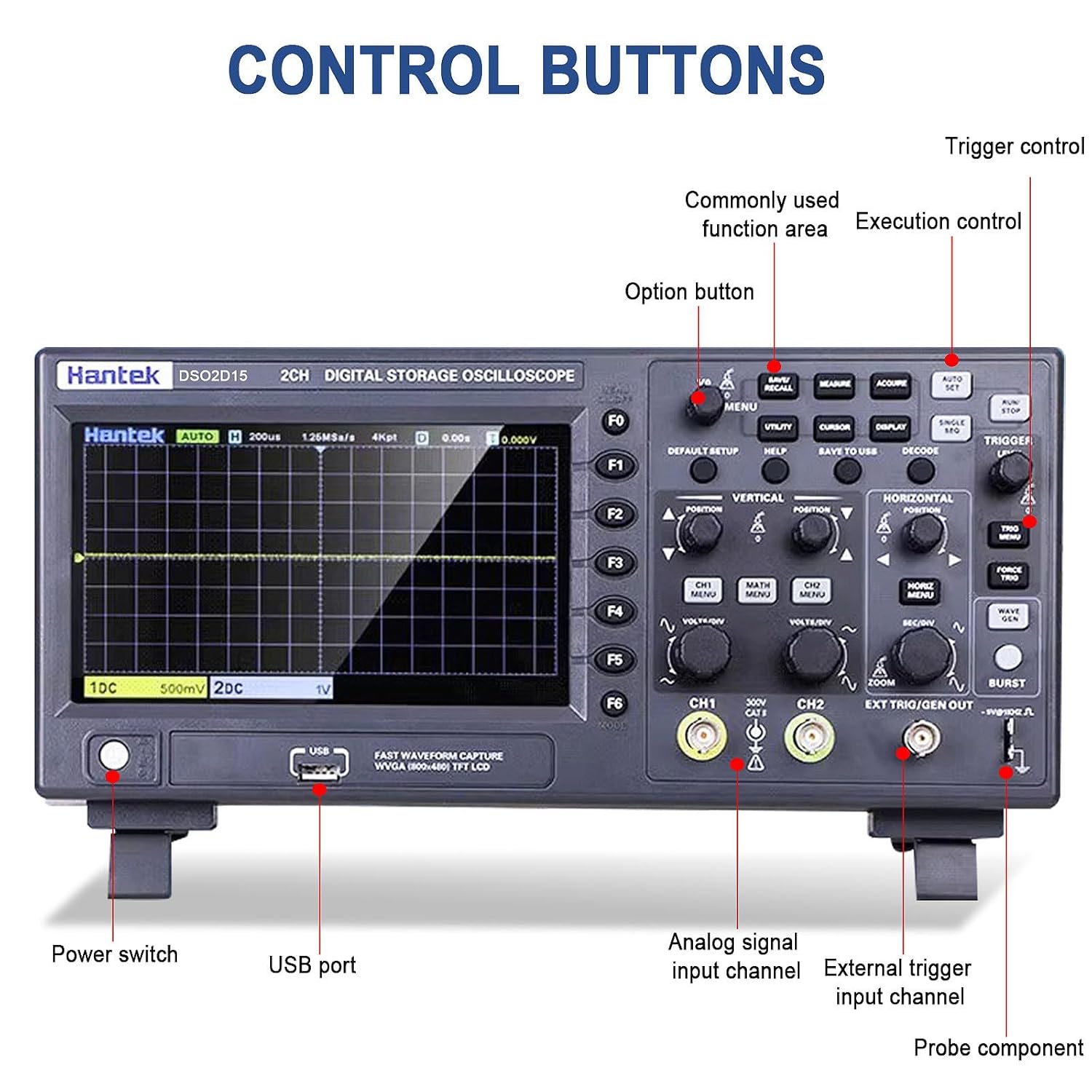
Figure 4.1: Labeled diagram of the Hantek DSO2D15 control panel, highlighting the power switch, USB port, analog signal input channels (CH1, CH2), external trigger input channel, and probe compensator output.

4.2 Funções do Osciloscópio

4.2.1 Operação em Canal Duplo

The DSO2D15 features two independent input channels (CH1 and CH2), each with its own vertical scale (VOLTS/DIV) and position control. This allows for simultaneous observation and comparison of two different signals.

Hantek DSO2D15 showing dual channel input

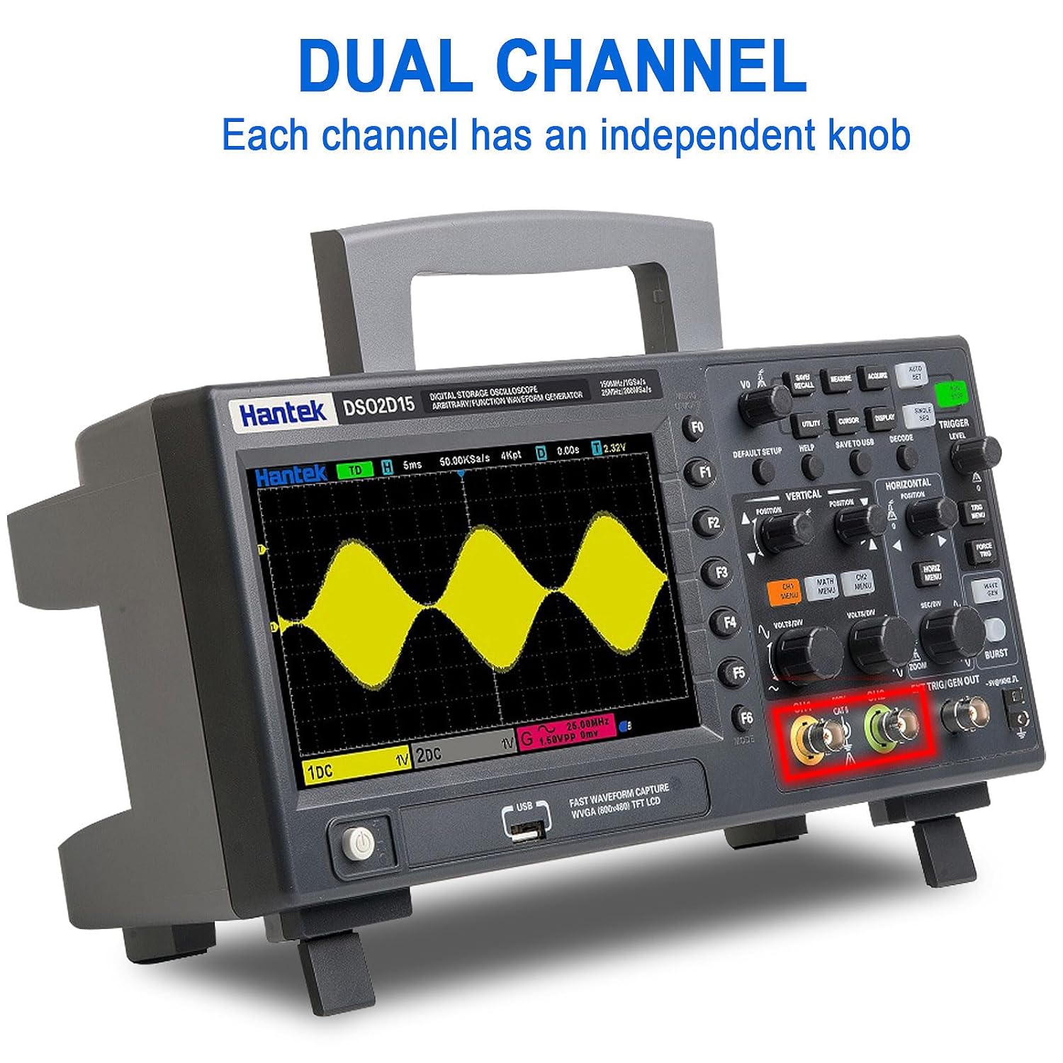
Figure 4.2: Display illustrating the dual-channel capability of the Hantek DSO2D15, with independent knob control for each channel.

4.2.2 Triggering System

The trigger system stabilizes repetitive waveforms and captures single-shot events. The DSO2D15 offers a wide range of trigger types:

  • Standard Triggers: Edge, Pulse, Video, Slope, Timeout, Window, Pattern, Interval, Undervoltage.
  • Serial Protocol Triggers: UART, LIN, CAN, SPI, IIC.

Use the "TRIGGER" section controls to select trigger type, level, and mode (Auto, Normal, Single).

Hantek DSO2D15 with multiple trigger functions highlighted

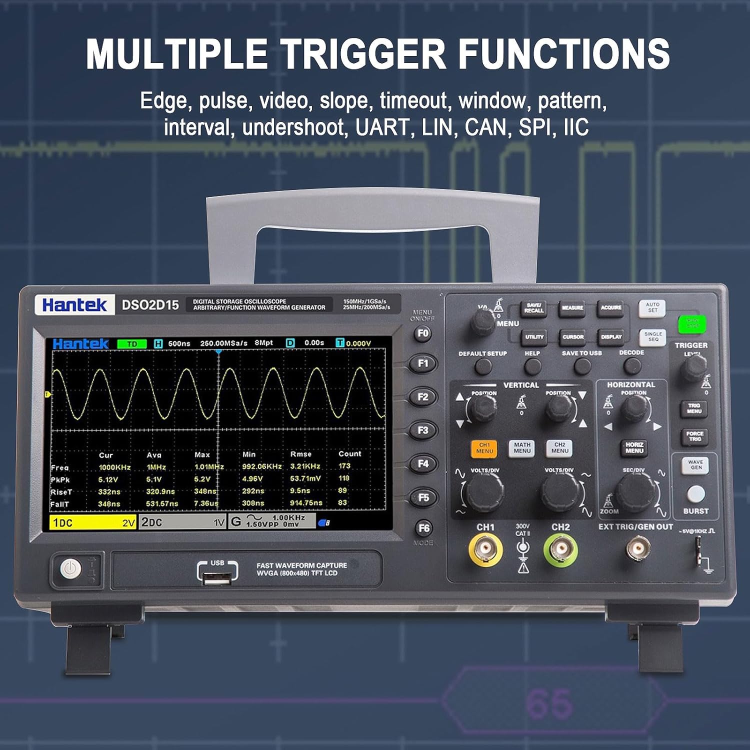
Figure 4.3: Screenshot of the Hantek DSO2D15 display demonstrating various trigger functions, including Edge, Pulse, Video, Slope, Timeout, Window, Pattern, Interval, Undershoot, UART, LIN, CAN, SPI, and IIC.

4.2.3 Measurement and Statistical Functions

The oscilloscope provides 32 automatic measurement parameters, including Frequency, Period, Average, Peak-to-Peak, RMS, Min, Max, Rise Time, Fall Time, and various duty cycles. Statistical analysis provides real-time calculations of minimum, maximum, and standard deviation for measurements.

Hantek DSO2D15 displaying measurement and statistical functions

Figure 4.4: The Hantek DSO2D15 screen showing the results of 32 automatic measurement and statistical functions, providing real-time statistics such as maximum, minimum, and standard deviation.

4.2.4 Saving and Recalling Data

The DSO2D15 allows users to save various data types, including instrument settings, captured waveforms, reference waveforms, CSV data, and screenshots (images). Use the "SAVE/RECALL" and "SAVE TO USB" buttons for these operations.

Hantek DSO2D15 control panel with save settings options

Figure 4.5: Close-up of the Hantek DSO2D15 control panel, highlighting the "SAVE/RECALL" and "SAVE TO USB" buttons for saving settings, waveforms, reference waveforms, CSV images, and other data formats.

4.3 Waveform Generator Function

The built-in 1-channel 25MHz arbitrary waveform generator can produce various standard waveforms (Sine, Square, Pulse, Triangle, Sample Wave, Exponential Wave, Noise) and user-defined arbitrary waveforms (Arb1-Arb4). This function is useful for testing circuits and systems.

  • Onda senoidal: Frequency Range 0.1Hz~25MHz
  • Square/Pulse Wave: Frequency Range 0.1Hz~10MHz
  • Onda triangular: Frequency Range 0.1Hz~1MHz
  • Arbitrary Wave: Frequency Range 0.1Hz~10MHz

Access the waveform generator settings via the dedicated "WAVE GEN" button or menu option.

5. Especificações

5.1 Parâmetros Gerais

ParâmetroValue (DSO2D15)
ModeloDSO2D15
Largura de banda150MHz
Oscilloscope Channel Count2 canais
Fonte de sinal integrada1 canais
Sampling Rate (Single Channel)1GSa/s
Sampling Rate (Dual Channel)500MSa / s
Maximum Record Length (Single Channel)8M
Maximum Record Length (Dual Channel)4M
Tipo de exibiçãoTela LCD TFT de 7"
Resolução de exibição800 (A) x 480 (V) pixels
Impedância de entrada1 MΩ ±2%, 13 pF ±3 pF
Vol. Máximo de Entradatage300 V RMS (10X)
Vol da fonte de alimentaçãotage100-240VAC RMS (±10%), 45-440Hz
Consumo de energiaMenos de 30W
Temperatura de operação0~50 °C (32~122 °F)
Dimensões do produto12.6 x 4.3 x 5.9 polegadas
Peso4.2 libras

5.2 Vertical System

  • Rise time at BNC (typical): 2.4 ns
  • Resolução vertical: 8-bit resolution, simultaneous sampling on each channel
  • Sensibilidade vertical: 2 mV/div a 10 V/div
  • Intervalo de compensação: ≤200 mV/div, ±1 V; >200 mV/div, ±50 V
  • Mathematical operations: Addition, subtraction, multiplication, division, FFT
  • FFT window: Rectangular, Hanning, Hamming, Blackman, Bartlett, Flat-top window
  • Bandwidth limit: 20 MHz
  • Low-frequency response (-3 dB): ≤10 Hz at BNC
  • Note: When using the X1 probe, the bandwidth is reduced to 6MHz.

5.3 Horizontal System

  • Waveform interpolation: (pecado x)/x
  • Horizontal scale range: 2ns/div to 100s/div, 1, 2, 5 steps
  • Time base mode: YT, XY, Roll
  • Incremental time measurement accuracy: Single, “Sample” mode
  • Sampling rate and delay time accuracy: ±50 ppm (for any time interval greater than 1 ms)

5.4 Trigger System

  • Tipos de gatilho: Edge, Pulse, Video, Slope, Timeout, Window, Pattern, Interval, Undervoltage, UART, LIN, CAN, SPI, IIC
  • Trigger Level Range: ±5 divisions from the screen center
  • Modo de gatilho: Automático, Normal, Único
  • Release range: 16 ns ~ 10 s

5.5 Waveform Generator (AWG)

  • Channel count: 1 canal
  • Samptaxa de ling: 200MSa / s
  • Resolução vertical: 12 bits
  • Frequência máxima: 25 MHz
  • Standard Waveforms: Sine, Square, Pulse, Triangle, Sample Wave, Exponential Wave, Noise
  • Formas de onda arbitrárias: Arb1, Arb2, Arb3, Arb4
  • Ampsolidão: Output Range 10 mV to 7 Vp-p (high impedance), 5 mV to 3.5 Vp-p (50 Ω)
  • DC Offset Range: ±3.5 V (high impedance); ±1.75 V (50 Ω)
  • Impedância de saída: 50 Ω
Model comparison table for Hantek oscilloscopes

Figure 5.1: A comparison table showing specifications across different Hantek oscilloscope models, including DSO2D15, highlighting channels, bandwidth, sampling rate, storage depth, signal source, and screen size.

6. Manutenção

6.1 Limpeza

To clean the exterior of the oscilloscope, use a soft cloth dampened with mild detergent and water. Do not use abrasive cleaners or solvents that could damage the plastic casing or display. Ensure the device is powered off and unplugged before cleaning.

6.2 Armazenamento

When not in use for extended periods, store the oscilloscope in a dry, dust-free environment, away from direct sunlight and extreme temperatures. The recommended storage temperature is -40~+71 °C (-40~159.8 °F).

6.3 Calibração

For optimal performance, periodic calibration by qualified personnel is recommended. Refer to the Hantek official website or contact support for calibration services.

7. Solução De Problemas

This section provides solutions to common issues you might encounter. For problems not listed here, please contact Hantek customer support.

ProblemaPossível causaSolução
Sem energiaPower cable not connected; Power outlet faulty; Fuse blown.Check power cable connection; Test power outlet; Replace fuse (T, 3.15A, 250V, 5x20mm) if necessary.
Nenhuma forma de onda exibidaProbe not connected or faulty; Input coupling incorrect; Vertical scale too high/low; Trigger not set correctly.Ensure probe is securely connected and functional; Set input coupling to DC or AC; Adjust VOLTS/DIV; Adjust trigger level or mode (try Auto).

Ask a question about this manual

Ask about setup, troubleshooting, compatibility, parts, safety, or missing instructions. Manuals+ will review the question and use this page’s manual context to help answer it.