ProTech SORADIO Connect Radio Module

529 VISTA BLVD 89434 SPARKS, NV – USA
Toll Free: 1-800-498-9662 / Phone: 775-856-7333 / Fax: 775-856-7658
Website: www.protechusa.com
E-mail: sales@protechusa.com
WIRING
| N° Terminals | Description |
| 1 | Input 1 |
| 2 | Common |
| 3 | Input 2 |
| 4 | Common |
| 5 | Input 3 |
| 6 | Common |
| 7 | Input 4 |
| 8 | Common |
| 9 | Input 5 |
| 10 | Common |
| 11 | Input 6 |
| 12 | Common |
| 13 | Input 7 |
| 14 | Common |
| 15 | Input 8 |
| 16 | Common |
| 17 | X |
| 18 | X |
| 19 | X |
| 20 | X |
| 21 | 0V Power supply |
| 22 | +12V DC Power supply |
Note: All common inputs are connected together.
Example of input wiring: 
The inputs are seen out of alarm when they are closed. They are seen in alarm when they are open (Positive security).
* LEDs status L1, L2 et L3:
| L1: green | Operating mode | OFF: Radio Mode ON: RS485 Mode (unused in SORADIO) | LEDs active only if BLE is activated after a short press on the tamper |
| L2: orange | Radio configuration status | Blinking: Radio mode not configured ON: Radio mode configured | |
| L3: red | BLE status | OFF: BLE deactivated Blinking: BLE active waiting for connection ON: BLE active connected to the application | |
Maximum length of 12V DC power supply cables: (cable type SYT1 shielded)
| Wire | Wire section | Maximum length of cables | |||
| 0.6 mm | 0.02 in | 0.3 mm² | 23 AWG | 500 m | 0.31 mi |
| 0.9 mm | 0.04 in | 0.6 mm² | 20 AWG | 1124 m | 0.7 mi |
| 1.4 mm | 0.06 in | 1.5 mm² | 16 AWG | 2506 m | 1.56 mi |
Note: When using the same cable to supply power to several components, the indicated distances should be divided by the number of connected components. When using several wires with the same section in parallel by polarity, the indicated distances should be multiplied by the number of connected wires.
SMARTPHONE APPLICATION
Note: The smartphone application is compatible from Android 4.1 or higher.
- Download the smartphone application “Sorhea Connect”.

- Launch application “Sorhea Connect”. Authorize activation of Bluetooth if requested to do so by the application.

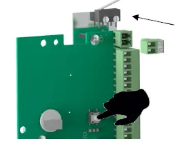
- Press the tamper switch very briefly (1s) to activate the BLE connection of the SORADIO.
Note: the connection remains active as long as the SORADIO is connected to the smartphone application. It is deactivated when the cover is closed (tamper closed) or after 1 minute of inactivity (application closed).
- Launch the search.
 Click on the product found.
Settings

Input status
 Note: It is possible to customize the name of an input. Click on the name to change and Save.
Input settings
Each input can be:
- Enable / disable input.
- Eject input.
To apply the changes, click Save.


Note: It is only possible to eject an input if it is enable.
- Input disable = Relay associated forced in alarm
- Input ejected = Relay associated forced out alarm.
User settings
Managing user settings allows saving settings or applying settings to inputs: name and status of inputs (activated, ejected).
Saving user configuration

Applying an existing user setting
 By default, the application offers the following setting options:


Event log
- Click on Menu

- Click on Event log

View event log
| List of events: |
| – Alarm |
| – End Alarm |
| – Eject |
| – End eject |
| – BLE Connection |
| – Configuration |
| – Time setting |
| – Reset log event |
| – Power on |
Network settings
- Click on Menu
- Click Network settings


RADIO CONFIGURATION
Configuration using the CONNECT RADIO COORDINATOR
- Enable radio, see §3.2.Activate the radio on the SORADIO.
Note: By default, the radio is disabled. - Refer to manual CONNECT RADIO COORDINATOR NT400 to start radio search.
- SORADIO settings and status from UNIVERSAL MAXIBUS
- Enable radio, see §3.2.Activate the radio on the SORADIO.

A. Product Name: Possibility to customize the name of the connected product. Change the name and click SAVE.
B. Reading network address RS485 (unused in SORADIO).
C. Input management:
For each input, it is possible to:
- Customize the name of the input.
- Enable / disable input.
- Input ejection.
To apply changes, click on SAVE.

D. Note: It is only possible to eject an input if it is enable.
Input disable = Relay associated forced in alarm
Input ejected = Relay associated forced out alarm.
E. Input State
(Note: status not available in radio mode)
![]() SORADIO Event log
SORADIO Event log
 List of “Events” available in event log:
- Start alarm
- Power on
- End alarm
- time setting
- Eject
- Change configuration
- End eject
- Reset event log
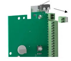
Activate the radio on the SORADIO
Note: radio activation allows resetting the radio configuration on the SORADIO and switching to radio search (wait for pairing with the CONNECT RADIO COORDINATOR)
|
1. Disconnect the power supply on the SORADIO |
|
|
2. Press the button and switch on the SORADIO |
|
|
3. Hold the button until the orange LED L2 lights. (≈ 5s, The green led L1 lights up during the procedure). |
|


MAINTENANCE
| Failure | Probable causes | Solutions |
| Permanent alarm | – Input disabled – Non-wired entry | – Activate input. – Check wiring. |
| Never alarm | – Input ejected | – Remove ejection from input |
| The smartphone application does not detect the SORADIO | – The BLE connection of the 8 INPUTS REMOTE MODULE is not activated. | – Press the tamper for at least 1 second. (see §3) |
TECHNICAL SPECIFICATIONS
| Power supply | 4.5V to 30V DC |
| Consumption | 10mA |
| Operating temperature | -35°C to +70°C / -31°F to 158°F |
| Relative humidity | 95% max. non-condensing |
| Protection index | IP65 |
| Weight | 0.3Kg / 0.66 lb |
| Electromagnetic compatibility | Compliance with European standards (label CE) |
| Range | Mesh network allowing messages to be relayed from MI8 to MI8: 400m / 0.25 mile point to point and in free field |
PRODUCT REFERENCES
- SORADIO
Option: - Pole mount bracket set Ø76
- Pole mount bracket set Ø101
- Bracket set for mounting on 100×50 pole or frame 3100 SF
- Bracket set for mounting on frame 3100 DF
ref: 30790001
ref: 30793001
ref: 30793002
ref: 30793003
ref: 30793004
Changes or modifications not expressly approved by PROTECH / SORHEA could void the user’s authority to operate the equipment.
FCC Part 15 compliance statement
This device complies with part 15 of the FCC Rules. Operation is subject to the following two conditions:
(1) This device may not cause harmful interference, and (2) this device must accept any interference received, including interference that may cause undesired operation.
This module has been approved under FCC part 15C 15.247. This modular transmitter is only FCC authorized for this specific rule part. – The module is limited to PROTECH / SORHEA installation only.
The host product should be check for compliance to any other FCC rules that apply to the host not covered by the modular transmitter grant of certification. (For example, Part 15 Subpart B).
If testing of the host product with this transmitter installed and operating is necessary (to verify that the host product meets all the applicable FCC rules), a test mode for this specific module is available upon request to SORHEA.
Trace antenna design, list of antenna type approved and professional installation is not applicable to this modular certification.
ISED (Canada) License-Exempt Radio Apparatus
This device contains license-exempt transmitter(s)/receiver(s) that comply with Innovation, Science and Economic Development Canada’s license-exempt RSS(s). Operation is subject to the following two conditions:
- This device may not cause interference.
- This device must accept any interference, including interference that may cause undesired operation of the device.
Radio Frequency (RF) Exposure Compliance of Radiocommunication for mobile Apparatus
To satisfy FCC and IC RF Exposure requirements for mobile devices, a separation distance of 20 cm or more should be maintained between the antenna of this device and persons during operation. To ensure compliance, operation at closer than this distance is not recommended. This transmitter must not be co-located or operating in conjunction with any other antenna or transmitter.
Host Product Labeling:
FCC Certification:
The final end product must be labeled in visible area with the following:
“Contains Transmitter Module FCC ID: QVA-SORADIO”
ISED Certification:
The final end product must be labeled in visible area with the following:
“Contains IC: 11664A-SORADIO”
Host Product User’s Manual:
The user manual for end users must include the following information in a prominent location
“IMPORTANT NOTE: To comply with FCC and ISED RF exposure compliance requirements, the antenna used for this transmitter must not be colocated or operating in conjunction with any other antenna or transmitter. The equipment should be installed and operated with a minimum distance of 20cm between the radiator and the body.”
Documents / Resources
 | ProTech SORADIO Connect Radio Module [pdf] Instruction Manual SORADIO, QVA-SORADIO, QVASORADIO, SORADIO Connect Radio Module, Connect Radio Module, Radio Module |


