1. Wprowadzenie
The Walfront MPPT Solar Charge Controller is designed to efficiently manage power flow from your solar panels to your battery bank, optimizing charging performance for off-grid solar systems. This manual provides essential information for the safe and effective installation, operation, and maintenance of your 50A MPPT solar charge controller.

Image 1.1: Walfront MPPT Solar Charge Controller 50A. This image shows the front view of the orange and black controller, featuring an LCD screen displaying PV, Battery, and Load information, along with 'ESC' and 'SET' buttons.
2. Główne cechy
- High Efficiency MPPT Tracking: Features MPPT tracking efficiency greater than 99% and a maximum conversion efficiency of up to 98%, maximizing energy harvest from solar panels.
- Wide 180V PV Input and Auto Voltage Rozpoznawanie: Supports a maximum solar input voltage of 180V (at 25℃) and automatically recognizes 12V, 24V, 36V, and 48V battery systems. Compatible with battery voltagod 9 V do 64 V.
- Clear LCD Display and Smart Protection: Built-in LCD provides real-time system data (voltage, current, operating status). Includes temperature compensation and multiple protection features for safe operation.
- Low No-Load Loss and Reliable Performance: No-load loss of ≤0.4W conserves energy. Designed for reliable operation in temperatures from -10℃ to 65℃ and altitudes up to 3000 meters.
- Łatwy w instalacji i obsłudze: Auto-recognition feature simplifies setup. Compact design allows for straightforward mounting.

Image 2.1: Automatic Voltage Identification. This image highlights the controller's ability to automatically identify 12V, 24V, 36V, and 48V systems, shown with various solar panel application examples.
3. Informacje dotyczące bezpieczeństwa
Please read all instructions carefully before installation and operation. Failure to follow these safety guidelines may result in personal injury, damage to the controller, or other equipment.
- Ensure all wiring is correctly polarized and securely connected. Loose connections can cause overheating and damage.
- Zawsze podłączaj najpierw akumulator, potem panel słoneczny, a na końcu obciążenie. Odłączaj w odwrotnej kolejności.
- Do not connect the solar panel array to the controller without a battery connected.
- Upewnij się, że system ma objętośćtage of the solar panel and battery are compatible with the controller's specifications.
- Zainstaluj kontroler w dobrze wentylowanym pomieszczeniu, z dala od materiałów łatwopalnych i bezpośredniego światła słonecznego.
- Avoid touching live terminals. Use insulated tools during installation.
- This device is not waterproof. Protect it from moisture and water exposure.
4. Zawartość opakowania
Sprawdź, czy w przesyłce znajdują się wszystkie elementy wymienione poniżej:
- 1 x Walfront MPPT Solar Charge Controller (50A)
- 4 x Śruby
- 4 śrub rozporowych
- 1 x Instrukcja obsługi (ten dokument)
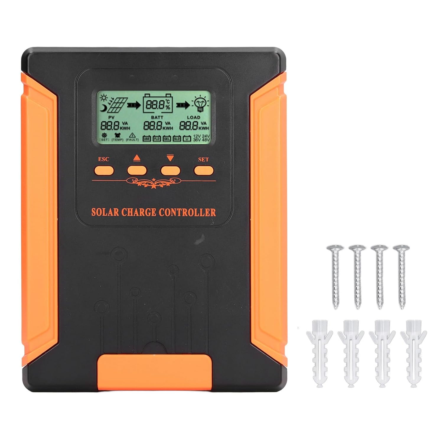
Image 4.1: Package Contents. This image displays the solar charge controller alongside the mounting screws and expansion screws provided in the package.
5. Konfiguracja i instalacja
Follow these steps for proper installation of your solar charge controller.
5.1 Montaż kontrolera
- Wybierz miejsce suche i dobrze wentylowane, chronione przed bezpośrednim działaniem promieni słonecznych, wysokimi temperaturami i wilgocią.
- Ensure there is sufficient space around the controller for heat dissipation, especially around the cooling fins.
- Mount the controller vertically on a solid surface using the provided screws.
5.2 połączeń przewodów
Refer to the wiring diagrams below for correct connection sequence. Always connect in the following order:
- Podłącz akumulator: Connect the battery to the controller's battery terminals. Ensure correct polarity (+ to + and - to -). The controller will automatically detect the battery voltage.
- Podłącz panel słoneczny: Connect the solar panel array to the controller's PV terminals. Ensure correct polarity.
- Podłącz obciążenie DC (opcjonalnie): Podłącz obciążenie DC do zacisków obciążenia kontrolera. Upewnij się, że polaryzacja jest prawidłowa.
To disconnect the system, follow the reverse order: disconnect load, then solar panel, then battery.

Image 5.1: Basic System Connection Diagram. This diagram illustrates the connection order: 1. Battery Assembly, 2. Solar Panel Assembly, 3. DC Load. It also shows an AC Load and Inverter connected to the Battery Assembly.

Image 5.2: Detailed System Wiring Diagram. This diagram provides a more comprehensive view of a solar power system, including solar panels, battery, inverter (AC Output/Input), and various AC loads like laptops, lights, air conditioners, televisions, and fans.
6. Instrukcja obsługi
The controller features an LCD display and control buttons for monitoring and configuration.
Wyświetlacz LCD 6.1
The LCD screen provides real-time information about your solar system, including:
- PV (Photovoltaic) Status: Objętość wejściowatage, current, and power from solar panels.
- BATT (Battery) Status: Pojemność bateriitage, charging current, and state of charge.
- LOAD Status: Output current and power to the DC load.
- Objętość systemutage: Automatically detected battery system voltagnp. (12V/24V/36V/48V).
- Wskaźniki błędów: Displays fault codes or warnings if issues occur.
6.2 przyciski sterujące
The controller has three buttons: ESC, Up/Down arrows, and SET.
- Przycisk ESC: Used to exit current menu or cancel an operation.
- Przyciski w górę/w dół: Used to navigate through menu options or adjust parameter values.
- Przycisk SET: Used to enter a menu, confirm a selection, or save changes to parameters.

Image 6.1: Control Buttons. This close-up image shows the 'ESC', 'Up arrow', 'Down arrow', and 'SET' buttons on the controller's front panel.
7. Konserwacja
Regularna konserwacja zapewnia optymalną wydajność i długowieczność regulatora ładowania słonecznego.
- Czyszczenie: Periodically clean the controller's exterior with a dry cloth. Ensure the cooling fins are free from dust and debris to maintain proper heat dissipation.
- Znajomości: Check all wiring connections regularly to ensure they are tight and free from corrosion.
- Kontrola: Inspect the controller for any signs of physical damage, overheating, or unusual odors.
- Środowisko: Ensure the installation environment remains dry and well-ventilated.

Image 7.1: Cooling Fins. This close-up shows the cooling fins on the top of the controller, which are crucial for heat dissipation and require regular cleaning.
8. Rozwiązywanie Problemów
Jeśli napotkasz problemy z kontrolerem, zapoznaj się z poniższymi typowymi problemami i rozwiązaniami:
| Problem | Możliwa przyczyna | Rozwiązanie |
|---|---|---|
| Wyświetlacz kontrolera jest wyłączony | Brak podłączonego akumulatora lub niski poziom naładowania akumulatoratage za niskie. | Ensure battery is connected correctly and has sufficient charge (above 9V). |
| Brak prądu ładowania z PV | Solar panels not connected, insufficient sunlight, or PV polarity reversed. | Sprawdź połączenia i polaryzację PV. Zapewnij odpowiednie nasłonecznienie. Sprawdź pojemność PV.tage jest w zasięgu. |
| Ładowanie nie działa | Load disconnected, load current too high, or load polarity reversed. | Check load connections and polarity. Ensure load current does not exceed controller's rating. |
| Bateria nie jest w pełni naładowana | Insufficient solar input, undersized solar array, or battery issues. | Increase solar panel capacity or check for shading. Inspect battery health. |
9. Specyfikacje techniczne
Below are the technical specifications for the Walfront MPPT Solar Charge Controller 50A.
| Parametr | Specyfikacja |
|---|---|
| Objętość systemutage | 12V / 24V / 36V / 48V Automatyczny |
| Znamionowy prąd ładowania | 50A |
| No Load Loss | ≤0.4W |
| Solar Maximum Input Voltage | 180V (at 25℃), 150V (at -25℃) |
| Pojemność bateriitage Zakres | 9-64 V |
| Maksymalny punkt mocy Voltage Zakres | Pojemność bateriitage +2V do 150V |
| Efektywność konwersji | ≤98% |
| Wydajność śledzenia MPPT | >99% |
| Współczynnik kompensacji temperatury | -2mv/℃/2V (default value) |
| Temperatura pracy | -10℃ do 65℃ |
| Stopień ochrony | IP21 |
| Wysokość | ≤3000 Meter / 9842.5ft |

Image 9.1: Model Comparison Table. This table provides a comparison of rated charging current and solar panel maximum input power for CM-50 (50A) and CM-60 (60A) models across different system voltagt.j.
10. Gwarancja i wsparcie
Aby uzyskać informacje o gwarancji i pomocy technicznej, zapoznaj się z dokumentacją dołączoną do produktu lub skontaktuj się ze sprzedawcą. Zachowaj paragon jako dowód zakupu.