1. Wprowadzenie
This manual provides detailed instructions for the installation, operation, and maintenance of your Bewinner LGA 1155 Motherboard. Please read this manual thoroughly before proceeding with installation to ensure proper setup and optimal performance.

Figure 1.1: Bewinner LGA 1155 Motherboard Overview
Na tym obrazie widać widok z góry na dół view of the Bewinner LGA 1155 Motherboard, showcasing its compact ITX form factor, the LGA 1155 CPU socket, DDR3 memory slots, various expansion slots, and I/O ports.
2. Zawartość opakowania
Sprawdź, czy wszystkie wymienione poniżej elementy znajdują się w Twojej paczce. Jeśli brakuje któregokolwiek z nich lub jest on uszkodzony, skontaktuj się ze sprzedawcą.
- 1 x Płyta główna Bewinner LGA 1155
- 1 x metalowa płytka wejścia/wyjścia
- 1 x Connection Cable (likely SATA data cable)
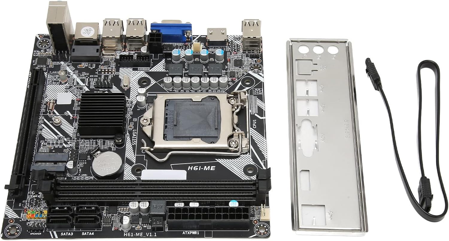
Figure 2.1: Motherboard and Accessories
This image shows the Bewinner LGA 1155 Motherboard alongside its included accessories: a metal I/O shield and a connection cable, typically a SATA data cable.
3. Funkcje produktu
The Bewinner LGA 1155 Motherboard is designed for desktop PCs, offering a range of features for reliable performance:
- Gniazdo procesora LGA 1155: Provides stable performance for compatible Intel processors.
- Multi-phase Power Supply: Ensures stable and precise power delivery to the CPU, enhancing overall system performance.
- Pamięć dwukanałowa DDR3: Supports up to 16GB of DDR3 RAM across two slots, significantly boosting motherboard performance.
- Extensive USB 2.0 Connectivity: Features 10 USB 2.0 interfaces (4 front-panel accessible) for various peripheral connections.
- Wyjście wideo HD: Equipped with VGA and HD Multimedia Interface (HDMI) for high-definition digital video output.
- Storage and Expansion: Includes 4 SATA2.0 connectors, PCIe 16X slot, and M.2 slots for both WiFi and NVME storage.
- Integrated Network Card: A 100M network card for reliable internet connectivity.

Figure 3.1: Motherboard Feature Highlights
This diagram visually highlights several key features of the motherboard, including the 2x DDR3 Dual Channel Memory Slots, PCIe 16X slot, 4* SATA2.0 ports, WIFI M.2 slot, NVME M.2 slot, 100M Network Card, and the Fin Cooling Design for heat dissipation.
4. Koniec komponentuview
Familiarize yourself with the layout of the motherboard's various components and connectors:

Rysunek 4.1: Rozmieszczenie komponentów płyty głównej
This image provides a labeled diagram of the motherboard, indicating the locations of the CPU Slot, 2x DDR3 Slots, 24Pin Motherboard Power Interface, 4*SATA2.0 ports, NVME M.2, WIFI M.2, Front USB2.0 headers, 2*USB2.0 ports, VGA port, 3Pin CPU Fan Pin, 4Pin CPU Power, 100M Network Card, 5.1 Track audio, PCIe 16X slot, and Debug Pin. It also shows the front panel header connections for PWR SW, RESET SW, PWR LED, and HDD LED.
- CPU Slot (LGA 1155): For installing compatible Intel processors.
- Gniazda pamięci DDR3: Two slots for DDR3 RAM modules.
- PCIe 16X Slot: For graphics cards or other expansion cards.
- Porty SATA 2.0: Four ports for connecting storage devices like HDDs and SSDs.
- Gniazda M.2: Dedicated slots for NVME SSDs and WiFi modules.
- 2.0 USB Porty: Rear I/O and front panel headers for USB devices.
- Wyjścia wideo: VGA and HD Multimedia Interface (HDMI) for display connectivity.
- Gniazda audio: Do podłączania głośników, słuchawek i mikrofonów.
- Port Ethernet: Do przewodowego połączenia sieciowego.
- Złącza zasilania: 24-pin ATX power and 4-pin CPU power connectors.
5. Konfiguracja i instalacja
Follow these general steps for installing your motherboard into a PC system. Always ensure your system is powered off and unplugged before handling components.
- Przygotuj sprawę: Zainstaluj osłonę I/O w tylnym otworze obudowy komputera.
- Zainstaluj procesor: Carefully open the CPU socket lever, align the CPU with the socket (matching the triangle indicator), gently place the CPU into the socket, and close the lever to secure it.
- Montaż chłodzenia procesora: Apply thermal paste (if not pre-applied) and install the CPU cooler according to its manufacturer's instructions. Connect the CPU fan cable to the motherboard's CPU_FAN header.
- Zainstaluj pamięć RAM: Open the clips on the DDR3 memory slots, align the RAM modules with the notch, and press firmly until the clips snap into place.
- Montaż płyty głównej: Ostrożnie umieść płytę główną w obudowie komputera, dopasowując ją do kołków dystansowych. Przymocuj ją śrubami.
- Podłącz zasilanie: Podłącz 24-pinowy kabel zasilający ATX i 4-pinowy kabel zasilający procesora do zasilacza i płyty głównej.
- Podłącz pamięć masową: Podłącz kable danych SATA z dysków twardych (HDD/SSD) do portów SATA na płycie głównej. Podłącz kable zasilania z zasilacza do dysków.
- Zainstaluj karty rozszerzeń: If using a dedicated graphics card or other PCIe cards, insert them into the PCIe 16X slot and secure them.
- Podłącz kable panelu przedniego: Connect the power button, reset button, HDD LED, and power LED cables from your case to the corresponding headers on the motherboard (refer to Figure 4.1).
- Connect USB/Audio Headers: Podłącz kable USB i audio na panelu przednim do odpowiednich złączy.

Figure 5.1: CPU Installation
This image illustrates the process of installing a CPU into the motherboard's socket, showing the CPU being lowered into place with heat radiating from it, symbolizing proper contact and function.
6. Instrukcja obsługi
Po zainstalowaniu i podłączeniu wszystkich komponentów można włączyć system.
- Pierwszy rozruch: After assembly, connect your monitor, keyboard, and mouse. Power on the system. The system should display the BIOS/UEFI splash screen.
- Dostęp do BIOS-u/UEFI: Podczas uruchamiania należy wielokrotnie nacisnąć wyznaczony klawisz (zwykle USUNĄĆ, F2, Lub F10) aby wejść do narzędzia konfiguracji BIOS/UEFI.
- Instalacja systemu operacyjnego: Configure boot order in BIOS/UEFI to install your operating system from a USB drive or optical drive.
7. Konserwacja
Proper maintenance ensures the longevity and stable operation of your motherboard and PC system.
- Usuwanie kurzu: Regularly clean dust from inside your PC case, especially from fans and heatsinks, using compressed air. Ensure the system is powered off and unplugged.
- Wentylacja: Ensure your PC case has adequate airflow and is placed in a well-ventilated area to prevent overheating.
- Aktualizacje BIOS-u/sterowników: Okresowo sprawdzaj producenta website for updated BIOS versions and drivers to improve compatibility and performance.
8. Rozwiązywanie Problemów
Jeśli napotkasz problemy, zapoznaj się z poniższymi typowymi krokami rozwiązywania problemów:
- Brak zasilania: Ensure all power cables (24-pin ATX, 4-pin CPU) are securely connected. Check the power supply unit (PSU) and wall outlet.
- Brak wyświetlacza: Verify that the monitor is connected to the correct video output (motherboard or graphics card). Reseat RAM modules and graphics card.
- Niestabilność/awarie systemu: Check CPU and GPU temperatures. Ensure all components are seated correctly. Test RAM modules individually.
- Komponent nie został wykryty: Reseat the component (e.g., RAM, SSD, PCIe card). Check BIOS settings to ensure it's enabled.
- Kody dźwiękowe POST: If the motherboard emits a series of beeps on startup, consult the BIOS manufacturer's documentation for the meaning of the beep code, which indicates specific hardware issues.
9. Specyfikacje
| Funkcja | Specyfikacja |
|---|---|
| Model płyty głównej | H6 ME |
| Typ płyty głównej | ITX |
| Typ gniazda procesora | LGA 1155 |
| Kompatybilne procesory | Intel Core i3/i5/i7/i9 (2nd and 3rd generation), Intel Pentium (2nd and 3rd generation), Intel Celeron (2nd and 3rd generation) |
| Typ chipsetu | Intel H61 Express |
| Gniazda pamięci | 2 x DDR3 |
| Maksymalna pojemność pamięci | 16 GB |
| Prędkość zegara pamięci | Do 2133 MHz |
| Złącza SATA | 4 x SATA2.0 |
| Graphics Adapter Slot | 1 x PCIe 16X |
| Interfejsy USB | 10 x USB2.0 (4 front) |
| Interfejsy rozszerzeń | 1 x VGA, 1 x HD Multimedia Interface (HDMI), 1 x WiFi M.2, 1 x NVME M.2, 1 x DEBUG pin |
| Karta sieciowa | 100 mln |
| Sound Audio Card | For Realtek ALC662 sound chip |
| Wbudowana bateria | 240 mAh CR2032 x 1 |
10. Informacje dotyczące bezpieczeństwa
Please observe the following warnings to ensure safe operation and prevent damage to the product or personal injury:

Rysunek 10.1: Ważne ostrzeżenie dotyczące bezpieczeństwa
This image displays a universal warning symbol alongside text in multiple languages. The core message is: If you find the product damaged, deformed, or exhibiting abnormal performance, please stop using it immediately and contact us.
- Always disconnect power from the PC before installing or removing any components.
- Handle the motherboard by its edges to avoid touching sensitive components and to prevent electrostatic discharge (ESD). Use an anti-static wrist strap if available.
- Aby zapobiec przegrzaniu, zadbaj o odpowiednią wentylację obudowy komputera.
- Nie wystawiaj płyty głównej na działanie wilgoci i ekstremalnych temperatur.
- If the product appears damaged or performs abnormally, discontinue use immediately and contact customer support.
11. Gwarancja i wsparcie
Aby uzyskać informacje o gwarancji i pomocy technicznej, zapoznaj się z dokumentacją dołączoną do zakupu lub skontaktuj się ze sprzedawcą. Zachowaj dowód zakupu na wypadek roszczeń gwarancyjnych.
For further assistance, you may also visit the official Bewinner webodwiedź witrynę lub skontaktuj się bezpośrednio z działem obsługi klienta.