1. Wprowadzenie
This manual provides essential information for the safe and efficient operation of your Cotek SP-3000-112 High Frequency Pure Sine Wave Inverter. This device converts 12V DC power from batteries into 120V AC power, suitable for a wide range of electronic appliances. Please read this manual thoroughly before installation and use, and retain it for future reference.
2. Informacje dotyczące bezpieczeństwa
Failure to follow these safety instructions may result in electric shock, fire, serious injury, or death. Always exercise caution when working with electrical equipment.
- Przeczytaj wszystkie instrukcje: Before operating the inverter, read all instructions and cautionary markings on the inverter, the batteries, and all appropriate sections of this manual.
- Wykwalifikowany personel: Installation and servicing should be performed by qualified personnel familiar with batteries and inverters.
- Wentylacja: Ensure adequate ventilation around the inverter. Do not install in a zero-clearance compartment.
- Unikaj wody: Do not expose the inverter to rain, snow, spray, or bilge water.
- Prawidłowe uziemienie: Falownik musi być prawidłowo uziemiony.
- Bezpieczeństwo baterii: Work near lead-acid batteries is dangerous. Batteries generate explosive gases during normal operation. Ensure proper ventilation and wear appropriate personal protective equipment.
- Odłącz zasilanie: Always disconnect the battery supply before performing any maintenance or troubleshooting.
- Poprawna cztage: Upewnij się, że napięcie wejściowe DCtage matches the inverter's specifications (12VDC for this model).


3. Koniec produktuview
3.1 Główne cechy
- Czysta fala sinusoidalna dla wrażliwej elektroniki.
- Power ON / OFF remote control capability (Green Terminal).
- Input & output fully isolated for enhanced safety.
- Temperature & load controlled cooling fan for optimal performance.
- Przyjazny dla użytkownika interfejs z 3-kolorowymi wskaźnikami stanu LED.
- Multiple protection features: Reverse Polarity (Fuse), Under Voltage / Ponad tomtage, Output Protection (Short Circuit / Overload / Over Temperature).
- E-13 / UL / CE / FCC approved.
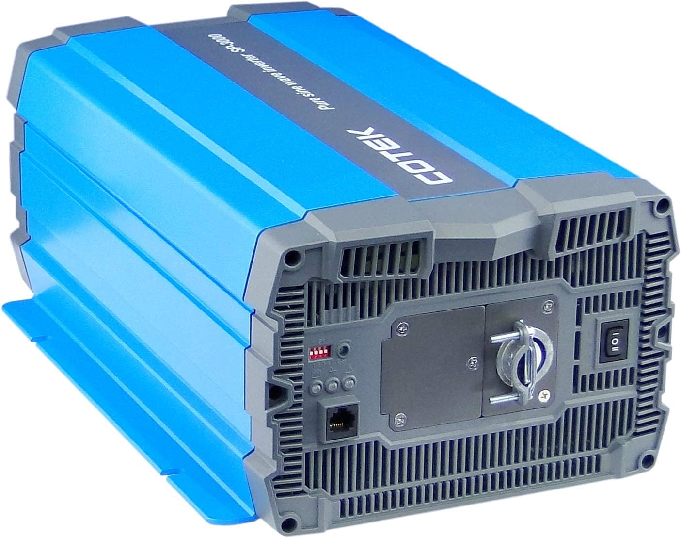
3.2 Elementy falownika

4. Konfiguracja i instalacja
Proper installation is crucial for the safe and efficient operation of your inverter. Refer to local electrical codes and standards.
4.1 Umieszczenie
- Install the inverter in a dry, well-ventilated area, away from direct sunlight, heat sources, and flammable materials.
- Ensure sufficient clearance around the inverter for proper airflow, especially around the cooling fan vents.
- Mount the inverter securely on a stable, non-combustible surface.
- Avoid areas where dust, moisture, or corrosive fumes are present.
4.2 Okablowanie
All wiring must comply with applicable electrical codes and be performed by a qualified electrician.
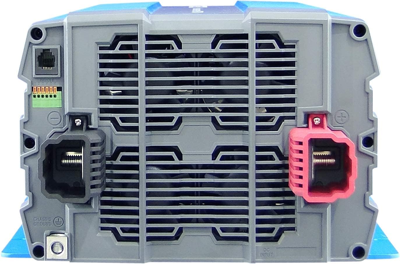
- Grunt: Connect the inverter's chassis ground terminal to a reliable earth ground using appropriate gauge wire.
- Połączenie wejściowe DC:
- Upewnij się, że pojemność akumulatoratage jest 12VDC.
- Use appropriately sized cables for the DC input to minimize voltage drop and ensure safety. Refer to cable sizing charts based on current and distance.
- Connect the positive (+) terminal of the battery bank to the red (+) terminal on the inverter.
- Connect the negative (-) terminal of the battery bank to the black (-) terminal on the inverter.
- Install a DC-rated fuse or circuit breaker between the battery bank and the inverter's positive terminal, as close to the battery as possible.
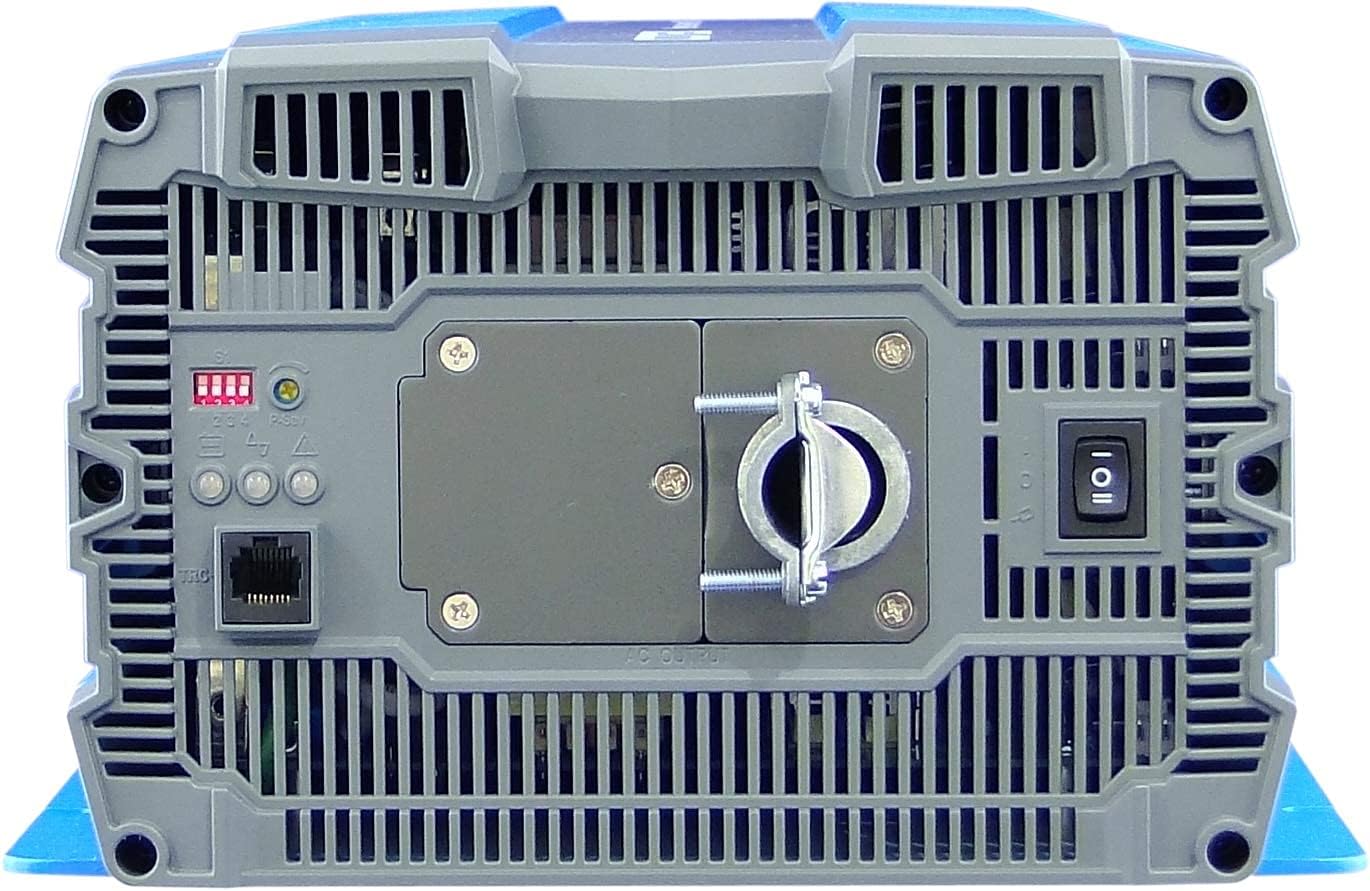
- Podłączenie wyjściowe prądu przemiennego:
- Connect your AC loads to the hardwire AC output terminal block.
- Ensure the total load does not exceed the inverter's continuous power rating (3000W).
- Pilot zdalnego sterowania (opcjonalnie): Connect the remote control unit to the RJ45 port or use the green terminal for external ON/OFF control if desired.
5. Instrukcja obsługi
5.1 Włączanie/wyłączanie
- Włączanie: Ensure all DC and AC connections are secure. Flip the main power switch on the inverter's rear panel to the 'ON' position. The Power LED indicator should illuminate.
- Aby wyłączyć: Disconnect all AC loads from the inverter. Flip the main power switch to the 'OFF' position.
5.2 Wskaźniki LED
The inverter features 3-color LED status indicators on the control panel (refer to Figure 4) to provide operational feedback:
- Zielona dioda LED: Indicates normal operation and power output.
- Żółta dioda LED: Indicates a warning condition, such as low battery voltage or high temperature. The inverter may continue to operate but requires attention.
- Czerwona dioda LED: Indicates a fault condition, such as overload, short circuit, or severe over/under voltage. The inverter will shut down to protect itself and connected devices.
5.3 Ustawienia przełącznika DIP
The DIP switches on the control panel allow for customization of certain inverter parameters, such as output voltage, frequency, and power saving mode. Refer to the detailed specifications table (Figure 5) or the product datasheet for specific configurations. Always adjust DIP switches when the inverter is powered off.
6. Konserwacja
Regularna konserwacja zapewnia długowieczność i niezawodną pracę falownika.
- Czyszczenie: Okresowo czyść zewnętrzną część falownika suchą ściereczką. Upewnij się, że otwory wentylacyjne są wolne od kurzu i zanieczyszczeń. Nie używaj płynnych środków czyszczących.
- Znajomości: Regularly check all electrical connections (DC input, AC output, ground) for tightness and corrosion. Loose connections can cause overheating and poor performance.
- Kontrola baterii: Inspect batteries for signs of damage, corrosion, or electrolyte leakage. Ensure battery terminals are clean and tight.
- Środowisko: Sprawdź, czy środowisko pracy mieści się w określonym zakresie temperatury i wilgotności.
7. Rozwiązywanie Problemów
W tej sekcji znajdziesz rozwiązania typowych problemów, z którymi możesz się spotkać. Jeśli problem będzie się powtarzał, skontaktuj się z obsługą klienta.
| Problem | Możliwa przyczyna | Rozwiązanie |
|---|---|---|
| Falownik się nie włącza. | No DC input power; Loose battery connections; Blown DC fuse/breaker; Inverter switch OFF. | Sprawdź pojemność akumulatoratage; Tighten connections; Replace fuse/reset breaker; Turn inverter switch ON. |
| Brak wyjścia AC. | Overload; Short circuit; Over-temperature shutdown; Low/High DC input voltage. | Reduce AC load; Check for short circuits in wiring/appliances; Allow inverter to cool; Check battery voltage. |
| Yellow LED illuminated. | Niski poziom naładowania akumulatoratage warning; High temperature warning. | Recharge batteries; Ensure adequate ventilation, reduce load. |
| Red LED illuminated / Inverter shut down. | Overload; Short circuit; Over-temperature; Under/Over voltage. | Identify and correct the fault (e.g., reduce load, fix short, allow cooling, check battery voltage), then restart the inverter. |
| Cooling fan runs constantly or loudly. | Wysoka temperatura wewnętrzna z powodu dużego obciążenia lub słabej wentylacji. | Reduce load; Improve ventilation around the inverter. |
8. Specyfikacje
The following table outlines the technical specifications for the Cotek SP-3000 Series Pure Sine Wave Inverter, specifically for the SP-3000-112 model.

| Kategoria | Parametr | SP-3000-112 |
|---|---|---|
| Wyjście | AC Objętośćtage | 100 / 110 / 115 / 120VAC ±5% |
| Moc znamionowa | 3000 W | |
| Surge Power (1 Sec.) | 6000 W | |
| Maksymalna moc wyjściowa (1 min) | 3450 W | |
| Przebieg wyjściowy | Pure Sine Wave (THD<3%) | |
| Częstotliwość | 50 / 60Hz ±0.5% | |
| Wejście | Objętość DCtage | 12 V prądu stałego |
| Tomtage Zakres | 10.5 ~ 16.5VDC | |
| Prąd bez obciążenia | <3.0 A przy 12 V prądu stałego | |
| Tryb oszczędzania energii | <0.4 A przy 12 V prądu stałego | |
| Wydajność (maks.) | 90% | |
| Ochrona | Input Under - Voltage Ochrona | 10.5 ±0.3 V prądu stałego |
| Input Under - Voltage Alarm | 11.0 ±0.3 V prądu stałego | |
| Input Under - Voltage Odzyskiwanie | 12.0 ±0.3 V prądu stałego | |
| Input Over - Voltage Ochrona | 16.5 ±0.3 V prądu stałego | |
| Input Over - Voltage Odzyskiwanie | 14.5 ±0.3 V prądu stałego | |
| Przeciążenie wyjściowe | Obj. wyjścia wyłączeniatage, uruchom ponownie, aby odzyskać | |
| Wyjście krótkie | Obj. wyjścia wyłączeniatage, uruchom ponownie, aby odzyskać | |
| Środowisko | Temperatura pracy | -20°C ~ +40°C |
| Temperatura przechowywania & Wilgotność | -30°C ~ +70°C, 10 ~ 95% RH | |
| Ogólny | Wymiary (szer. x wys. x gł.) | 442 × 214 × 102 mm (17.4 × 8.4 × 4.0 cala) |
| Waga | 8.2 kg (18.1 funtów) | |
| Chłodzenie | Wentylator chłodzący sterowany temperaturą i obciążeniem |

9. Gwarancja i wsparcie
9.1 Informacje o gwarancji
The Cotek SP-3000-112 Pure Sine Wave Inverter comes with a Roczna gwarancja producentaNiniejsza gwarancja obejmuje wady materiałowe i wykonawcze powstałe w wyniku normalnego użytkowania. Prosimy zachować dowód zakupu na potrzeby roszczeń gwarancyjnych.
9.2 Obsługa klienta
For technical assistance, troubleshooting beyond this manual, or warranty inquiries, please contact Cotek customer support through their official website or your point of purchase. Provide your model number (SP-3000-112) and a detailed description of the issue to expedite service.