Parrot Uncle F8001 Large Size Ceiling Fan

Safety Information
- To reduce the risk of an electrical blow, electricity on the protective switch or the safety box went out before starting.
- AII wiring must correspond to the NASI/NFPA 70-1999 National Electric Code and local electrical regulations. The electrical installation must be carried out by a qualified and approved electrician.
- The connection box and support construction must be assembled safely and 35 pounds (15.9 kilos) must be able to transport reliably. Use only output boxes listed with labeling “Accepted for fans with a weight of 35 lbs (15.9 kg) or less.”
- The fan must be installed with a minimum distance of 2.1 m (7 feet) from the posterior edge of the wings to the floor.
- Do not operate the reverse switch if the fan wings are moving. You have to turn off the fan and stop the wings before reverse the direction of the wing.
- Do not place objects on the road to wings.
- To avoid lesions or damage to the fan and other objects, be careful if you work on the fan or clean it.
- ELectrical diagrams only serve as a reference. The lighting rates that are not delivered with the fan must be listed and marked with the valve model that will be installed for use. The switches must be general use switches UL. Take into account the instructions for the appropriate installation included in the lighting rates and the switches.
- After the electrical connections have been made, the size staircase must be turned up and carefully push to the plug box. The cables must be distributed in such a way that the ground connected driver and the device head are next to the socket.
All fixing screws must be verified before installation and, if necessary, followed.
- WARNING: To reduce the risk of injury, knife supports (also known as flanges) cannot be folded during installation or after installation. Do not put any object on the path of wings.
- WARNING: Remove rubber motor attacks at the bottom of the fan before mounting the wings or try the engine.
- WARNING: To avoid the risk of a fire or an electrical blow, this fan should not be used with a semiconductor speed controller.
- WARNING: To avoid a possible electric shock, turn off the current in the main security box before wiring. If you feel that you do not have enough knowledge or experience in electrical wiring, communicate with a license electrician.
- WARNING: Electrical diagrams only serve as a reference. The optional use of a lighting rate must be on the list and marked with this fan for use.
- WARNING: To reduce the risk of fires, electrical discharges, or injuries, assemble the device in a socket that with the inscription is accepted for fans with a weight of 35 lbs (15.9 kg) or less. It is marked and use the screws supplied with the plug.
TECHNICAL INFORMATION
| SKU | Nominal voltage | Nominal output (motor) | Light |
| F8001BK | 110V AC | 38W | 22W (included) |
| F8002BK | 110VAC | 50W | 22W (included) |
| F8001SY | 110V AC | 38W | 22W (included) |
| F8002 SY | 110V AC | 50W | 22W (included) |
WARNING: SHUT POWER OFF AT FUSE OR CIRCUIT BREAKER
Parts
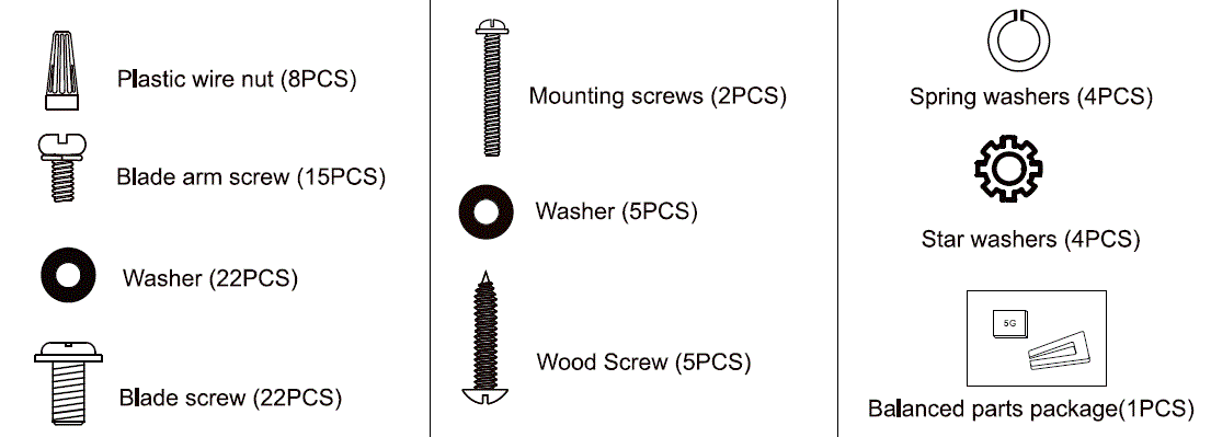

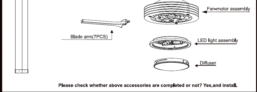
Installation Instructions
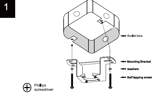
Mount the mounting bracket to the outlet box using two self tapping screws, two stars washers and two washers.
- WARNING: To reduce the risk of fire,electric shock or personal injury, mount to an outlet box marked “Acceptable for fan support • of 35 lbs (15.9kg) or less , ” and use the screws provided with the outlet box.
- NOTE: The mounting bracket(A) is designed to slide into place on an outlet box with the outlet box screws(LL).
INSTALLATION OF SAFETY CABLE SUPPORT
Attach the wood screw and the flat washer tothe ceiling joist as shown (do not fully tighten). Slide the cable clamp onto the safety cable from the fan. Loop the safety cable around the wood screw that was just attached to celling Jolts. Feed the end of the cable into the clamp and pull as much cable through as possible. Firmly tighten screw in the damp. Cut off excess cable.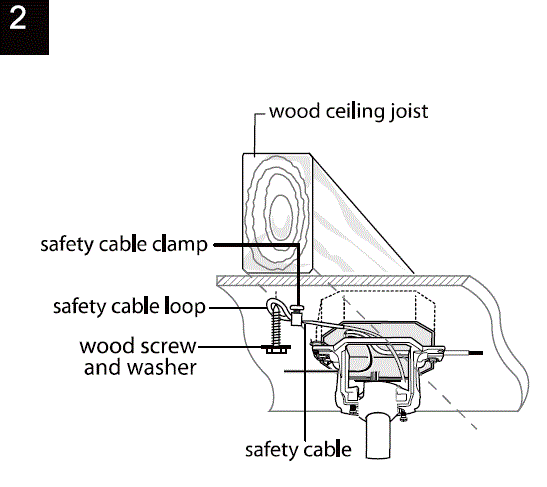
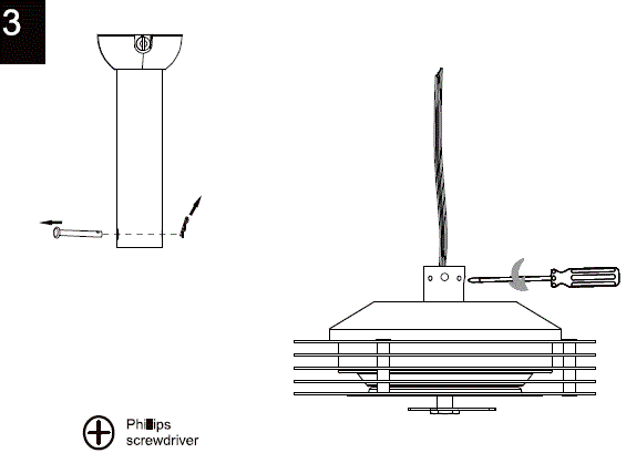
- Remove the hanging pin and “R” locking pin from the downrod.
- Loosen the two screws at the top of the fan-motor assembly.
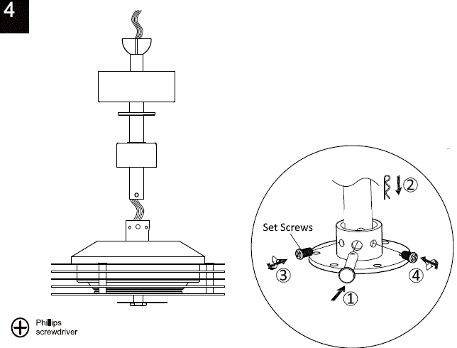
- Pass the downrod assembly through the canopy,canopy cover,coupling cover. Run the wires of the fan-motor assembly through the downrod assembly.
- Thread the hanging pin through the fan-motor assembly and insert the “R”locking pin. Lock the two screws.
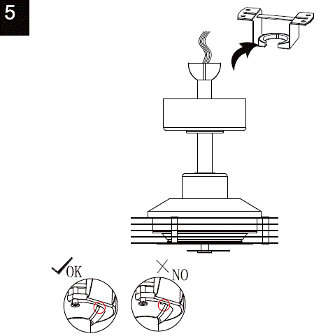
- Install the fan-motor assembly into the mounting bracket, taking care to install it in place.
- Use the shoulder screw to lock the canopy to the mounting bracket.
- FROM POWER SOURCE AC 110-120 VOLT 60Hz 3.5AMPS.
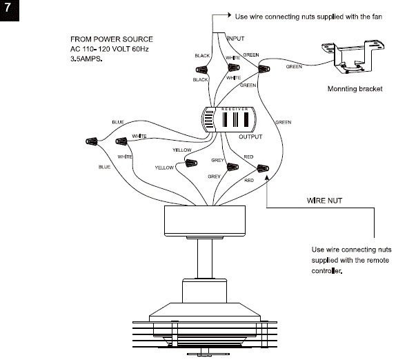
Install remote control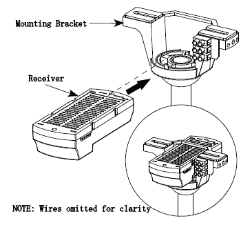
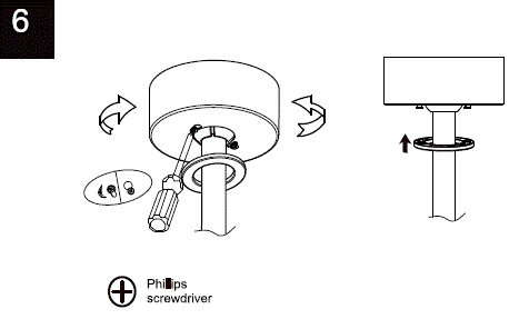
- Carefully push the canopy to the bottom of the mounting bracket, make two sliding holes aligned to the two prominent screws on the mounting bracket, and then turn clockwise until tight.
- Push the canopy ring to the bottom of the canopy, slide the inner holes aligned to the two prominent screws on the mounting bracket again, and turn the canopy ring clockwise until tight.
Preparing for mounting
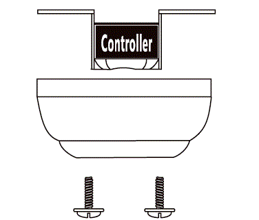
- Remove the mounting bracket from the canopy by loosening the two canopy screws located in the L shaped slots.’
- Remove and save the two canopy screws in the round holes. This will enable you to remove the mounting bracket.
Parts adjustment
- Attend the blade arm to fan-motor assembly use two blade arm screws.
- Repeat this step six times.
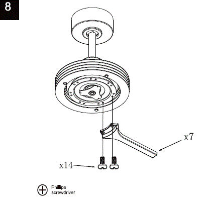
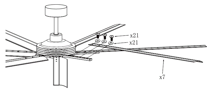
- Attand the blade to blade arm use three blade scerws and three washer.
- Repeat this step six times.
Screw Assembly
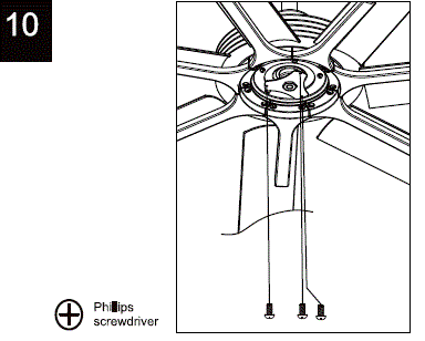
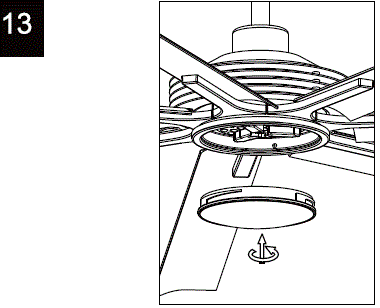
- Loosen three screws from the fan-motor assembly.
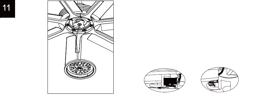
- Connect the wire connector to the LED light assembly.
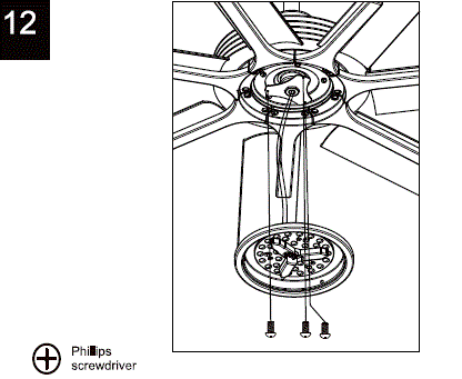
- Attach the LED light assembly to the fan-motor assembly use three screws.
- Attach the diffuser to the LED light assembly fixture by gently turning the cover anti-clockwise until it is fixed firmly in place.
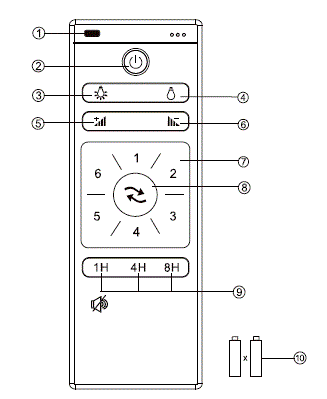
Description
- LED indicated light
- OFF the fan
- ON the light
- OFF the light
- Turn up the brightness of light
- Turn down the brightness of light
- Speed of the fan
- Direction of the fan (reverse switch)
- Timing control of the fan
PS:Turn on the supply power within 20 seconds press and hold the “1 H”button can
ON/OFF the “Beep”sound of the receiver. - I. 5V AAA battery x 2pcs
- If there are two or more ceiling fans installed in the same house, in order to prevent your ceiling fans from being affected by the remote control of the adjacent ceiling fans.
(Power-off means you need to use a wall switch to shut down the power of the ceiling fan, if you do not have a wall switch, please power off the whole room from the air circuit-breaker for each room)
After installing the remote control receiver on the ceiling fan
- Turn on the power of the 1# ceiling fan receiver (the power of the 2# receiver is kept in a power-off state), Turn on the supply power within 5 seconds and press the REMOTE CONTROL
 ” button for 5 seconds, it can load normally after hearing a long sound “bee”, which means learning successfully and it can works normally.
 - Turn on the power of the 2# ceiling fan receiver (the power of the 1# receiver is kept in a power-off state), Turn on the supply power within 5 seconds and press the REMOTE CONTROL
 ‘ button for 5 seconds, it can load normally after hearing a long sound “bee”, which means learning successfully and it can works normally.
WARNING:
Do NOT install this fan with variable speed wall control or wall-mounted dimmer switch. It will permanently damage the fan’s remote control and cause the fan’s function to fail.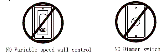
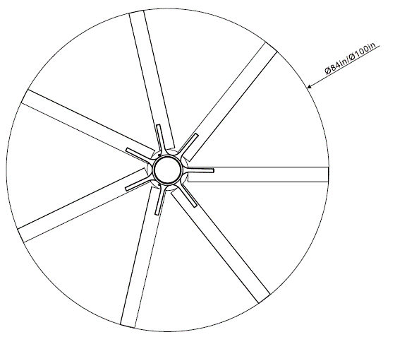
Size of product

 AFTER INSTALLATION
WOBBLE
The fan blades have been adjusted in the factory to minimize any wobble.
NOTE. CEILING FANS TEND TO MOVE DURING OPERATION DUE TO THE FACT THAT THEY ARE MOUNTED ON A MOUNTING BRACKET. IF THE FAN WAS MOUNTED RIGIDLY TO THE CEILING, IT WOULD CAUSE EXCESS VIBRATION. MOVEMENT OF A FEW CENTIMETERS IS QUITE ACCEPTABLE AND DOES NOT SUGGEST ANY PROBLEM.
TO REDUCE THE FAN WOBBLE: PLEASE CHECK THAT ALL SCREWS WHICH SECURED THE MOUNTING BRACKET AND DOWNROD ARE SECURE.
BALANCING A WOBBLING CEILING FAN:
- Check that all blade and blade arm screws are secure.
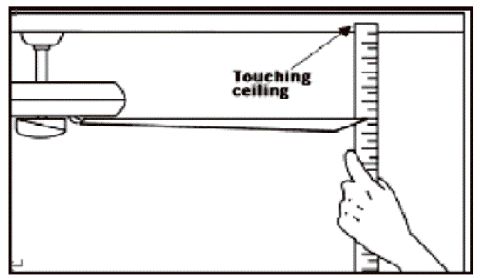
- Most fan wobbling problems are caused when blade levels are unequal. Check this level by selecting a point on the ceiling above the tip of one of the blades. Measure this distance-Rotate the fan until the next blade is positioned for measurement. Repeat for each blade. The distance deviation should be equal within Q32cm).
WARNING: TO REDUCE THE RI SK OF PERSONAL INJURY, DO NOT BEND THE BLADE ARM WHILE INSTALLING, BALANCING THE BLADES, OR CLEANING THE FAN. DO NOT INSERT FOREIGN OBJECTS BETWEEN ROTATING FAN BLADES.
NOISE
When it is quiet (especially at night) you may hear occasional small noises. This is normal. Please allow a 24 – hour “breaking-in” period, most noises associated with a new fan disappear during the time.
LIGHT IS NOT WORKING
- Ckeck Bulb to make sure it is installed correctly.
- Remove non-working bulb and replace with a bulb that is known to be a good working bulb.
- To reset the remote control:Turn off power to fan using the wall switch or circuit breaker,remover batteries from remote,wait 10 seconds,replace batteries and turn power on.
CARE AND CLEANING
- Periodic cleaning of your ceiling fan is the only maintenance required. Use a soft brush or lint free cloth to avoid scratching the paint finish. Please make sure to turn off electricity power before you dean your fan.
- Do not use water when cleaning your ceiling fan. It could damage the motor or the blades and create the possibility of an electrical shock.
- Motor has permanently lubricated ball bearing. Do not need to oil fan.
NOTE: MAKE SURE THE POWER IS OFF AT THE ELECTRICAL PANEL BOX BEFORE YOU ATTEMPT ANY CLEANING OR REPAIRS.
FCC Statement
This device complies with Part 15 of the FCC Rules. Operation is subject to the following two conditions.
- This device may not cause harmful interference.
- This device must accept any interference received, including interference that may cause undesired operation.
Changes or modifications not expressly approved by the party responsible for compliance could void the user’s authority to operate the equipment.
NOTE: This equipment has been tested and found to comply with the limits for a Class B digital, pursuant to Part 15 or the FCC Rules. These limits are designed to provide reasonable protection against harmful interference in a residential installation. This equipment generates, uses and can radiate radio frequency energy and, if not installed and used in accordance with the instructions, may cause harmful interference to radio communications, However, there is no guarantee that interference will not occur in a particular installation. If the equipment does cause harmful interference to radio or television reception, which can be determined by turning the equipment off and on, the user is encouraged to try to correct the interference by one or more of the following measures:
- Reorient or relocate the receiving antenna.
- Increase the separation between the equipment and receiver.
- Connect the equipment into an outlet on a circuit different from that to which the receiver is connected.
- Consult the dealer or an experienced radio/ TV technician for help.
Documents / Resources
 | Parrot Uncle F8001 Large Size Ceiling Fan [pdf] Installation Guide F8001, F8002, F8001 Large Size Ceiling Fan, F8001, Large Size Ceiling Fan, Ceiling Fan, Fan |