![]()
LEM-6
3-6 Channel Interface
User Manual 
This manual is copyright © 2006-2021 Newtons4th Ltd. and all rights are reserved. No part may be copied or reproduced in any form without prior written consent.
Document Title: LEM6 User Manual v2.0 Document Release Date: 1 st February 2021 Firmware version: N/A
Document Ref: D000208 Issue 2
LEM-6 6 Channel Analyzer Interface
IMPORTANT SAFETY INSTRUCTIONS
This equipment is designed to comply with BSEN 61010-1 (2010) (Safety requirements for electrical equipment for measurement, control, and laboratory use) – observe the following precautions:
- This instrument is to be connected and operated only by qualified personnel.
- This appliance must be earthed. Ensure that the instrument is powered from a properly grounded supply before connecting to any live inputs.
- Ensure that the supply voltage agrees with the rating of the instrument printed on the back panel before connecting the mains cord to the supply.
- Keep the ventilation slots in the top and sides of the cover free from obstruction.
- Do not operate or store under conditions where condensation may occur or where conducting debris may enter the case. Do not use in a wet environment.
- There are no user serviceable parts inside the instrument – do not attempt to open the instrument, refer service to the manufacturer or his appointed agent.
Note: Newtons4th Ltd. shall not be liable for any consequential damages, losses, costs or expenses arising from the use or misuse of this product however caused.
DECLARATION OF CONFORMITY
Newtons4th Ltd.
1 Bede Island Road
Leicester
LE2 7EA
We declare that the product:
Description: LEM CT Interface
Product name: LEM6
Model: LEM6-x Family
Conforms to the EEC Directives:
2014/30/EU relating to electromagnetic compatibility:
EN 61326-1:2013
EN 55022 class A
EN 61000-3-2:2014
EN 61000-3-3:2013
2014/35/EU relating to Low Voltage Directive:
EN 61010-2-030:2010
EN 61010-1:2010
January 2021
Jigar Patel
(Senior Engineer Newtons4th Ltd.)
WARRANTY
This product is guaranteed to be free from defects in materials and workmanship for a period of 36 months from the date of purchase.
In the unlikely event of any problem within this guarantee period, first contact Newtons4th Ltd. or your local representative, to give a description of the problem. Please have as much relevant information to hand as possible – particularly the serial number.
If the problem cannot be resolved directly then you will be given an RMA number and asked to return the unit. The unit will be repaired or replaced at the sole discretion of Newtons4th Ltd.
This guarantee is limited to the cost of the instrument itself and does not extend to any consequential damage or losses whatsoever including, but not limited to, any loss of earnings arising from a failure of the product or software.
In the event of any problem with the instrument outside of the guarantee period, Newtons4th Ltd. offers a full repair and re-calibration service – contact your local representative. It is recommended that the instrument be re-calibrated annually.
ABOUT THIS MANUAL
This manual describes the general features, usage and specifications of the LEM6-x range of LEM CT interfaces.
Getting started
LEM6 is supplied ready to use – it comes complete with an appropriate power lead and a set of test leads. It is supplied calibrated and does not require anything to be done by the user before it can be put into service.
1.1 Temperature Limits
The temperature limits for storage of the instrument and during shipping / transportation are: -20˚C to +70˚C
The instrument must be within 5˚C of the ambient temperature before operation.
1.2 Unpacking
Remove the instrument and accessories from the packaging and check them against the supplied packing list. Please contact your N4L office or local sales distributor should any items found to be missing or damaged during transportation.
Please retain the original packaging to ensure easy and safe return of the equipment for calibration etc.
Before connecting the test leads to an active circuit first connect the mains cord from a properly grounded supply outlet to the inlet on the rear panel of the LEM6. LEM6 has a universal mains input and accepts any supply voltage from 100-240VAC at 50 or 60Hz, maximum 6A.
Switch on the LEM6 and allow 30 minutes warm up time before commencing any measurements in order to ensure accurate results.
In the event of any problem with this procedure, please contact customer services at Newtons4th Ltd. or your local authorised representative: contact addresses and telephone numbers are given in the appendix at the back of this manual.
Description of operation
N4L LEM-6 Interface serves as a high accuracy, highly stable interfacing unit allowing simple “plug and play” connection of any N4L PPA to the LEM current transducers listed in Appendix A.
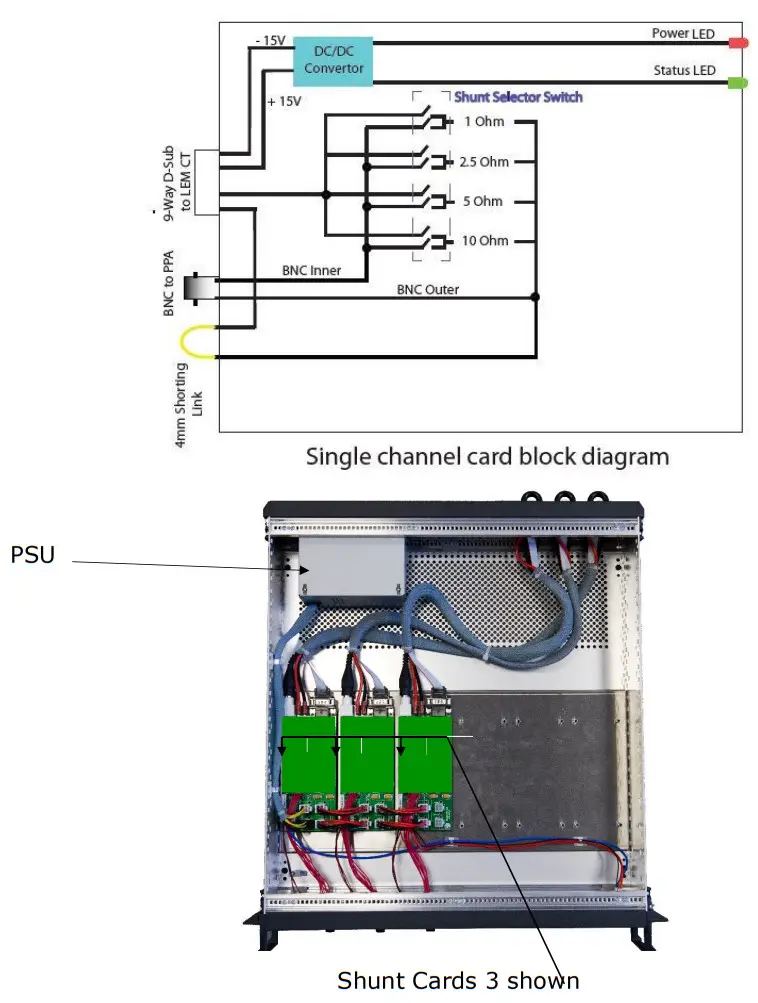
The LEM-6 supplies the LEM transducer with a highly stable isolated supply voltage; each channel is isolated from the next providing excellent cross channel coupling immunity. There are 4x current shunts per channel, ranging from 1Ω ~ 10Ω, this ensures the transducer can be utilized accurately throughout its dynamic range without the introduction of noise into the measurement.
The LEM-6 is 19-inch rack mountable and available in 3~6 phase configurations.
Basic circuit inside LEM
 Pin out
Each channel is connected from the LEM6 on the rear 9 pin D Sub connector to the LEM CT via the supplied interface lead.
4.1 9 Pin D-sub pinout diagram

4.2 Connection Diagram
Setting up LEM6
5.1 Choice of shunt
Each channel of the LEM6 has a selection switch to choose between the four available shunt values of 1Ω, 2.5Ω, 5Ω, and 10Ω.
Some care and consideration should be taken into the selection of the correct shunt value for each channel as well as the choice of CT.
The combination should be chosen to give as close to 3Vpk as the output from the BNC marked PPA.
In a typical application the correct shunt should be chosen from the supported range (see Appendix B) so that the expected current to be measured is close to the top range of the CT, with a tolerance.
For example, if you suspect the measured current to be approx. 500Apk then the IT405-S would be ideal.
The conversion ratio is 1:1500 therefore 500Apk would give a secondary current Is of 333mApk
For an ideal of 3Vpk output this would give a shunt value of 9Ω, however if the closest numerical value shunt of 10Ω were chosen, then the Ext input limit of 3Vpk would be exceeded. Therefore the 5 Ω shunt would be used in this case.
The EXT input of the PPA has 8* calibrated ranges from the maximum 3Vpk down to 1mVpk*, i.e. a 3000:1* ratio. So, in most cases, lower current (and therefore voltage into the EXT input) is handled by the wide range system without any risk of overage damage if current is higher than expected. Consequently, wherever possible the 1 Ohm shunt should be selected unless current is so low that sensitivity needs to be increased further. Overage of the lower ranges is not a problem, If, for example 3Vpk is applied when the 1mV range is selected, there will be an overage message, but no damage will occur to the EXT input. However, the 3Vpk limit MUST NOT be exceeded as this will damage the EXT input.
Once the shunts values have been chosen, they should not require changing until the rig is used to test a different set up.
If they need to be changed then for the increased longevity of the shunt selection switch, the switch should only be changed when under no load with no current flowing through the switch.
*9, 300µVpk, and 10000:1 for the PPA5500 series.
5.2 Setting PPA Ranges
Setting up the PPA depends upon whether the LEM-6 is being used as part of a calibrated system or not.
If the LEM-6 is purchased with an N4L power analyzer and LEM transducers, the LEM-6 Interface can be “system calibrated” within N4L’s ISO17025 UKAS laboratory. This provides the engineer with a single uncertainty figure and improved accuracy performance.
5.2.1 Use with non-system calibrated CT’s
Press the SYS key
Press the DOWN ARROW key until Independent ranging is highlighted red
Press the RIGHT ARROW, select Enabled with the DOWN ARROW key.
Press ENTER key twice to return to the power analyzer screen.
Press the RANGE key.
Press the DOWN ARROW key five* times until Current Input is highlighted.
Press RIGHT ARROW key, then DOWN ARROW key to select External shunt.
*If voltage channel is set to external, Current input will be selected by an additional press of the DOWN ARROW 
Press ENTER key
Press DOWN ARROW key 3 times and set the Scale factor to suit the CT in use. The scale factors are listed in section 7 Appendix A.
For example, the scale factor would need to be set to 1000 for an IT200-S as shown below. 
Press the ENTER key to save the new scale factor value.
Now press the DOWN ARROW once to select the shunt value. Set the shunt value to the actual value from calibration label on the right-hand side of the case. Shown ringed in red for clarity.

Press the ENTER key to save the new shunt value.
Press the HOME key then using RIGHT ARROW key go to the next phase.
Repeat the preceding steps for each phase, setting the scale factor and shunt values from the calibration label.
5.2.2 Use with system calibrated CT’s
Note:
The following procedure is for system calibrations that have all CT’s connected to the external inputs of the instrument.
For setups only having CT’s on certain inputs or using a combination of internal and external inputs, the instrument should first have independent ranging enabled in the SYS menu options. The Range instructions below will then have to be repeated for each phase to individually set each phase to internal or external shunt.
Press the RANGE key.
Press the DOWN ARROW key five* times until Current Input is highlighted.
Press RIGHT ARROW key, then DOWN ARROW key to select External shunt.
*If voltage channel is set to external, Current input will be selected by an additional press of the DOWN ARROW Press the ENTER key twice. 
Press AUX to open the AUX menu.
Press DOWN ARROW 3 times to highlight External system scaling.
Press RIGHT ARROW
Press DOWN ARROW to select enabled.
Press ENTER key
Press DOWN ARROW to highlight Phase 1
Press RIGHT ARROW, this now displays a sub menu showing shunts available.
Using the DOWN ARROW selects shunt value, press ENTER and in blue the adjustment value for the selected shunt is shown.
Press ENTER. 
Repeat for each channel of the LEM6.
The adjustment value for each shunt is shown: Press the Enter Key. 
If RANGE is pressed the RANGING menu will confirm that the external system scaling has been selected in the AUX menu, by displaying the Scale factor and the nominal shunt value in green text.  The above screenshot shows the settings for Phase 1. The left and right arrow keys can be used to display the settings for Phase 2 and Phase 3.
Specifications
| Number of Phases Number of Ranges Compatible Transducers Output Voltage @ BNC connector Output Current @ 4mm Terminal Shunt Accuracy (Typical with system calibration, Dependent on CT chosen) | 3 – 6 4 (1.0Ω, 2.5Ω, 5.0Ω, & 10.0Ω) See Appendix A +/- 3Vpk +/- 1Apk 0.1% 0.04% |
Physical
| Size Weight | LEM-6 – 90H x 450W x 485D mm – Excl. feet 6.0kg – 6 phase |
Electrical
| Safety isolation Power supply Interface Cable Length Output connectors | Conductor may need extra insulation dependent on CT chosen, consult appropriate LEM data sheet. 100-240 VAC 50-60Hz 2 meters standard – Up to 6 meters available as an option Safety BNC (voltage) or 4mm (current) – shorting links supplied |
Environmental
| Operating Temperature Range Storage Temperature Range Relative Humidity Range Maximum Altitude | 0°C to +50°C -20°C to +70°C 20 to 95% Non-Condensing 2,000 Meters |
All specifications at 23˚C ± 5˚C.
These specifications are quoted in good faith but Newtons4th Ltd reserves the right to amend any specification at any time without notice
Appendix A – Compatible CT’s
| Model Number | Current Rating | Conversion Factor |
| IT60-S | 60Apk 42Arms | 600 |
| 1165-5 § | 85Apk 60Arms | 600 |
| IN100-S | 150Apk 100Arms | 500 |
| IT200-S | 200Apk 141Arms | 1000 |
| IN200-S | 300Apk 200Arms | 1000 |
| IT205-S § | 283Apk 200Arms | 1000 |
| IT400-S | 400Apk 282Arms | 2000 |
| IN400-S | 600Apk 400Arms | 1500 |
| 11405-5 § | 566Apk 400Arms | 1500 |
| IT600-S | 400Apk 282Arms | 1500 |
| ITN600-S | 600Apk 424Arms | 1500 |
| IT605-S § | 849Apk 600Arms | 1500 |
| IT700-S | 700Apk 495Arms | 1750 |
| LF510-S * | 800Apk 500Arms | 5000 |
| LF1010-S * | 2700Apk 1000Arms | 5000 |
| LF2010-S * | 4250Apk 2000Arms | 5000 |
*Overall accuracy at Primary nominal RMS current
LF510-S 0.6%
LF1010-S 0.4%
LF2010-S 0.3%
[0.1% with system calibration AC+DC]
CT’s marked § are legacy devices no longer available new
7.1 Appendix B – Contact Details
Please direct all queries or comments regarding the LEM-6 instrument or manual to:
Newtons4th Ltd.
1 Bede Island Road
Leicester
LE2 7EA
United Kingdom
Tel: (0116) 230 1066 international +44 116 230 1066
Fax: (0116) 230 1061 international +44 116 230 1061
E-mail address: sales@newtons4th.com office@newtons4th.com
web site: www.newtons4th.com
At Newtons4th Ltd. we have a policy of continuous product improvement and are always keen to hear comments, whether favorable or unfavorable, from users of our products.
An example comment form can be found at the end of this manual – if you have any comments or observations on the product please fill a copy of this form with as much detail as possible then fax or post it to us.
Alternatively send an e-mail with your comments.
| LEM-6 comments | ||
| serial number: | date: | |
| your contact details: | ||
| comments: | ||
| detailed description of application or circumstances: | ||
| Please post or fax to Newtons4th Ltd. | ||
![]()
Documents / Resources
 | Newtons4th LEM-6 6 Channel Analyzer Interface [pdf] User Manual LEM6-x Family, LEM-6, LEM-6 6 Channel Analyzer Interface, 6 Channel Analyzer Interface, Analyzer Interface, Interface |