1. Introduzzjoni
This manual provides detailed instructions for the installation, configuration, and operation of the MD430 Stepper Motor Controller Board Driver, featuring the TB6560 chip. This single-axis driver is designed for controlling stepper motors with a maximum current of 3.5A and supports up to 16 microsteps, making it suitable for various automation and motion control applications.
2. Informazzjoni dwar is-Sigurtà
Please read and understand all safety precautions before installing or operating this device. Failure to comply with these instructions may result in electrical shock, fire, or damage to the product or connected equipment.
- Ensure power is disconnected before making any wiring connections.
- Verify correct polarity for all power connections.
- Taqbiżx il-vol speċifikattage u klassifikazzjonijiet kurrenti.
- Install the board in a well-ventilated area to prevent overheating.
- Avoid touching components while the board is powered.
3. Karatteristiċi tal-prodott
- Integrated TB6560AHQ chip for reliable stepper motor control.
- Single-axis control for one stepper motor.
- Maximum output current: 3.5A.
- Microstepping capabilities: 1, 2, 8, 16 microsteps.
- Adjustable current settings.
- Overheat and overcurrent protection.
- Compact design with integrated heatsink for efficient heat dissipation.
4. Identifikazzjoni tal-Komponent
Familiarize yourself with the various components on the MD430 driver board:

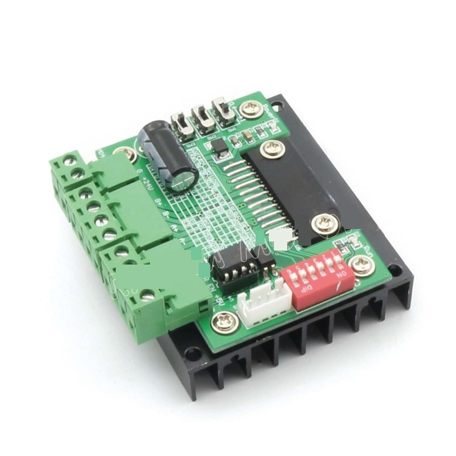

Il-komponenti ewlenin jinkludu:
- Power Input Terminals: Għall-konnessjoni tal-provvista tal-enerġija DC.
- Motor Output Terminals: For connecting the stepper motor windings (A+, A-, B+, B-).
- Control Signal Input: Terminals for Step, Direction, and Enable signals.
- Swiċċijiet DIP: Used to configure microstepping resolution and output current.
- Heatsink: Large black aluminum heatsink for thermal dissipation.
5. Setup u Wiring
Follow these steps to correctly set up and wire your MD430 stepper motor driver:
- Konnessjoni tal-Provvista tal-Enerġija:
Connect a DC power supply (typically 12V-36V) to the power input terminals. Ensure correct polarity: +V to positive, GND to negative. The power supply should be capable of providing sufficient current for your motor (e.g., 24V, 5A).
- Stepper Motor Connection:
Connect your 4-wire or 6-wire stepper motor to the motor output terminals (A+, A-, B+, B-). For 6-wire motors, connect the center taps to the power supply positive or leave them disconnected, depending on your motor type and desired configuration (unipolar/bipolar). Refer to your motor's datasheet for specific wiring.
- Control Signal Connection:
Connect your control signals (STEP, DIR, EN) from your microcontroller or CNC controller to the corresponding input terminals on the MD430 board. Ensure common ground connection between the controller and the driver.
- STEP (CLK): Pulse input for each step.
- DIR (CW/CCW): Direction control input (High/Low).
- EN (ENA): Enable input (Low to enable, High to disable motor current).
- Konfigurazzjoni tal-Iswiċċ DIP:
Configure the DIP switches for desired microstepping resolution and output current. Refer to the tables below for settings. Always adjust DIP switches when power is off.
Microstepping Settings:
Mikrostep S1 S2 S3 1 (Full Step) ON ON ON 2 (Half Step) OFF ON ON 8 (1/8 Step) ON OFF ON 16 (1/16 Step) OFF OFF ON Note: ON typically means the switch is pushed down or towards the "ON" label. OFF means up or away from "ON".
Settings kurrenti:
L-ogħla Kurrenti S4 S5 S6 0.5A ON ON ON 1.0A OFF ON ON 1.5A ON OFF ON 2.0A OFF OFF ON 2.5A ON ON OFF 3.0A OFF ON OFF 3.5A ON OFF OFF 4.0A (Mass) OFF OFF OFF Note: The maximum current for the TB6560 is typically 3.5A. Setting it to 4.0A might exceed the chip's safe operating limits and is not recommended for continuous use. Match the current setting to your motor's rated current.
6. Istruzzjonijiet Operattivi
Once the MD430 driver board is correctly wired and configured:
- Qawwa Mixgħul: Apply power to the driver board. The motor should be energized (if EN is low).
- Send Step Pulses: Send pulse signals to the STEP input from your controller. Each pulse will cause the motor to move one step (or microstep, depending on configuration).
- Control Direction: Change the logic level (High/Low) on the DIR input to reverse the motor's rotation direction.
- Enable/Disable Motor: Set the EN input to low to enable the motor and high to disable it. When disabled, the motor will be free-spinning and consume less power.
Monitor the motor and driver for excessive heat during operation. If the heatsink becomes too hot to touch, reduce the current setting or improve ventilation.
7. Manutenzjoni
The MD430 stepper motor driver board requires minimal maintenance. Follow these guidelines:
- Keep the board clean and free from dust and debris.
- Ensure adequate airflow around the heatsink to prevent overheating.
- Periodically check all wiring connections for tightness and integrity.
- Avoid exposing the board to moisture or corrosive environments.
8 Issolvi l-problemi
| Problema | Kawża Possibbli | Soluzzjoni |
|---|---|---|
| Motor does not move. | No power, incorrect wiring, EN pin high, no step pulses, motor current too low. | Check power supply, verify motor and control wiring, ensure EN is low, check step pulse generation, increase current setting. |
| Motor moves erratically or vibrates. | Incorrect microstep setting, motor wiring issues, insufficient power, mechanical binding. | Verify microstep DIP switch settings, recheck motor phase wiring, ensure power supply is stable, check for mechanical obstructions. |
| Driver board overheats. | Motor current too high, insufficient ventilation, short circuit in motor wiring. | Reduce motor current setting, ensure adequate airflow around heatsink, check motor wiring for shorts. |
| Motor rotates in the wrong direction. | DIR signal polarity incorrect, motor phase wiring reversed. | Reverse the DIR signal logic (High/Low) or swap one pair of motor phase wires (e.g., A+ with A-). |
9. Speċifikazzjonijiet
- Mudell: MD430
- Ċippa tas-Sewwieq: TB6560AHQ
- Input Voltage: 12V - 36V DC (Recommended)
- Kurrent tal-Ħruġ: 0.5A - 3.5A (Adjustable, Peak 4.0A)
- Microstepping: 1, 2, 8, 16 (selectable via DIP switches)
- Protezzjoni: Overheat, Overcurrent
- Dimensjonijiet: Approximately 1.18 x 0.79 x 0.39 inches (Board only, excluding heatsink/terminals)
- Piż: Madwar 1.76 uqija
10. Garanzija u Appoġġ
Information regarding warranty and customer support for this product was not provided in the available data. Please refer to the seller or manufacturer's website for specific details regarding warranty terms and technical assistance.
For further assistance, you may contact the seller chengbaihuoshangmao via their Amazon seller page: Bejjiegħ Profile.