 LVX6048WP Parallel
Installation Guide
Introduction
This inverter can be used in parallel with maximum 6 units. The supported maximum output power is 36KW/36KVA.
Parallel cable
You will find the following items in the package:

Overview

- Current sharing port
- Parallel communication port
Mounting the Unit
When installing multiple units, please follow below chart.

NOTE: For proper air circulation to dissipate heat, it’s necessary to allow a clearance of approx. 20 cm to the side and approx. 50 cm above and below the unit. Be sure to install each unit in the same level.
Wiring Connection
The cable size of each inverter is shown as below:
Recommended battery cable and terminal size for each inverter:
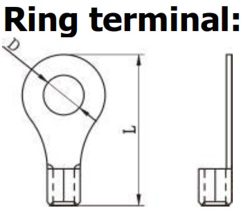
| Wire Size | Rin Terminal | Torque value | ||
| Cable mm2 | Dimensions | |||
| D (mm) | L (mm) | |||
| 2 | 34. | 8. | 43. | 7~12 Nm |
WARNING: Be sure the length of all battery cables is the same. Otherwise, there will be voltage difference between inverter and battery to cause parallel inverters not working.
Recommended AC input and output cable size for each inverter:
| AWG no. | Conductor cross section | Torque |
| 10~8 AWG | 5.5~10 mm 2 | 1.4~1.6Nm |
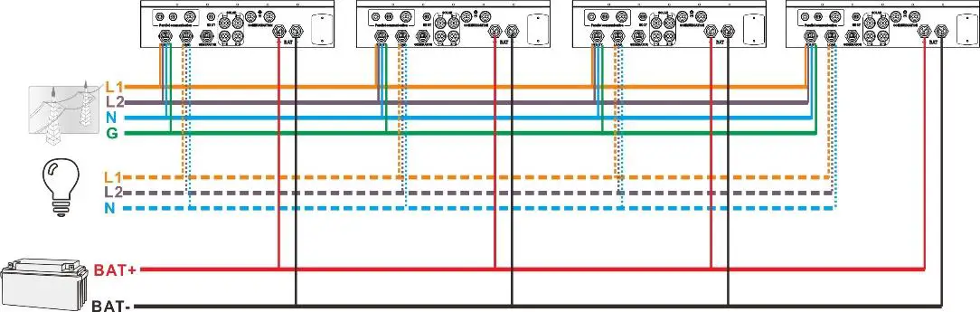
You need to connect the cables of each inverter together. Take the battery cables for example. You need to use a connector or bus-bar as a joint to connect the battery cables together, and then connect to the battery terminal. The cable size used from joint to battery should be X times cable size in the tables above. “X” indicates the number of inverters connected in parallel. Regarding cable size of AC input and output, please also follow the same principle.
CAUTION!! Please install a breaker at the battery side. This will ensure the inverter can be securely disconnected during maintenance and fully protected from overcurrent of battery.
Recommended breaker specification of battery for each inverter:
One unit*
200A/60VDC
*If you want to use only one breaker at the battery side for the whole system, the rating of the breaker should be X times current of one unit. “X” indicates the number of inverters connected in parallel.
Recommended battery capacity
| Inverter parallel numbers | 2 | 3 | 4 | 5 | 6 |
| Battery Capacity | 400AH | 600AH | 800AH | 1000AH | 1200AH |
CAUTION! Please follow the battery charging current and voltage from battery spec to choose the suitable battery. The wrong charging parameters will reduce the battery lifecycle sharply.
Approximate back-up time table
| Load (W) | Backup Time @ 48Vdc 400Ah (min) | Backup Time @ 48Vdc 600Ah (min) | Backup Time @ 48Vdc 800Ah (min) | Backup Time @ 48Vdc 1000Ah (min) | Backup Time @ 48Vdc 1200Ah (min) |
| 12000 | 90 | 140 | 180 | 240 | 280 |
| 18000 | 60 | 90 | 120 | 160 | 180 |
| 24000 | 40 | 70 | 90 | 120 | 140 |
| 30000 | 35 | 55 | 75 | 90 | 110 |
| 36000 | 30 | 50 | 60 | 80 | 100 |
PV Connection
Please refer to user manual of single unit for PV Connection.
CAUTION: Each inverter should connect to PV modules separately.
Inverters Configuration
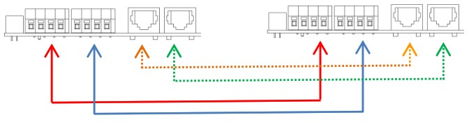
Two inverters in parallel:
Power Connection

Communication Connection
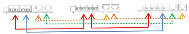
Three inverters in parallel:
Power Connection

Communication Connection
Four inverters in parallel:
Power Connection
Communication Connection
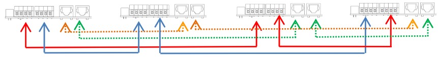
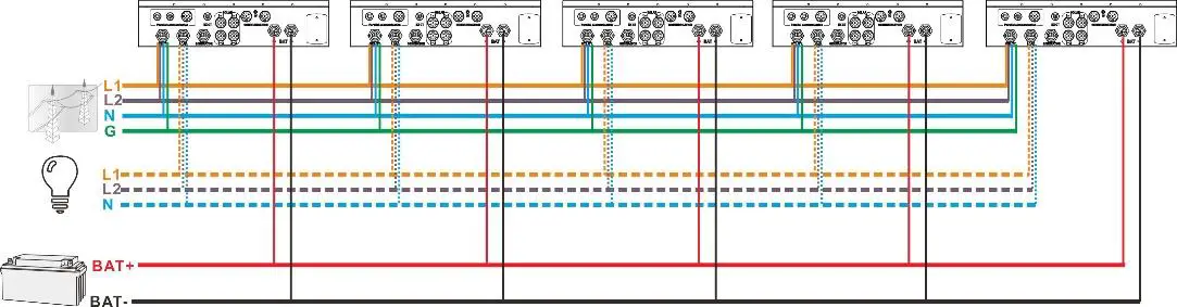
Five inverters in parallel:
Power Connection
Communication Connection
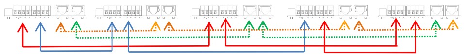
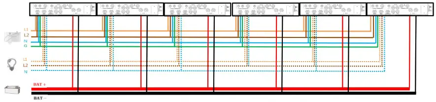
Six inverters in parallel:
Power Connection
Communication Connection

Setting and LCD Display Setting Program:
The parallel function setting is only available in Solar Power or Solar Power Pro software.
Please install software in your PC first.
For setting, you can set the inverter one by one through USB port.
- Use USB to synchronize the parameters:
Parallel for output: Enable/Disable

Fault code display:
| Fault Code | Fault Event | Icon on |
| 60 | Power feedback protection | |
| 61 | Relay board driver loss | |
| 62 | Relay board communication loss | |
| 71 | Firmware version inconsistent | |
| 72 | Current sharing fault | |
| 80 | CAN fault | |
| 81 | Host loss | |
| 82 | Synchronization loss |
Commissioning
Step 1: Check the following requirements before commissioning:
• Make sure all wires correctly connected.
• Ensure all breakers in Line wires of load side are open and each Neutral wire of each unit is connected together.
Step 2: Turn on each unit and set “enable parallel for output” on Solar Power or Solar Power Pro. And then, shut down all units.
Step 3: Turn on each unit.

NOTE: Master and slave units are randomly defined. Warning 02 is AC GRID voltage low.
Step 4: Switch on all AC breakers of Line wires in AC input. It’s better to have all inverters connected to utility at the same time. If not, it will display fault 82 in the slave inverters. However, these inverters will automatically restart. If detecting AC connection, they will work normally.

Step 5: If there is no more fault alarm, the parallel system is completely installed.
Step 6: Please switch on all breakers of Line wires in load side. This system will start to provide power to the load.
Trouble shooting
| Situation | Solution | |
| Fault Code | Fault Event Description | |
| 60 | Current feedback into the inverter is detected. | 1.Restart the inverter. 2.Check if L1/L2/N cables are not connected with wrong sequence in all inverters. 3.Make sure the sharing cables are connected to all inverters. 4.If the problem remains, please contact your installer. |
| 61 | Relay board driver loss | 1.Disconnect all of power source. 2.Only connect AC input and press Enter key to let it working in bypass mode. 3.Check if the problem happens again or not and report the result to your installer. |
| 62 | Relay board communication loss | |
| 71 | The firmware version of each inverter is not the same. | 1.Update all inverter firmware to the same version. 2.After updating, if the problem still remains, please contact your installer. |
| 72 | The output current of each inverter is different. | 1.Check if sharing cables are connected well and restart the inverter. 2.If the problem remains, please contact your installer. |
| 80 | CAN data loss | 1.Check if communication cables are connected well and restart the inverter. 2.If the problem remains, please contact your installer. |
| 81 | Host data loss | |
| 82 | Synchronization data loss | |
Documents / Resources
 | MPP Solar LVX6048WP Parallel [pdf] Installation Guide LVX6048WP Parallel, LVX6048WP, Parallel |


