MICTUNING P1s Gang Switch Panel with App Control

Package Included
| Accessories | Quantity |
| 1 |
 | 1 |
 | 5 |
 | 1 |
 | 10 |
 | 2 |
 | 3 |
 | 3 |
 | 10 |

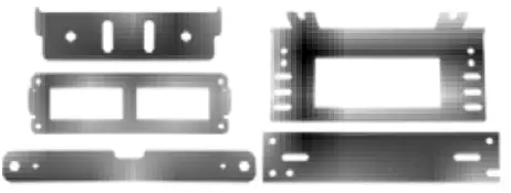
Switch Panel Installation

Control Box Installation

Switch Panel Installation
- WAY 1
- Align the bracket with hole position

- Tighten the flat head screws

- Installation finished

- Align the bracket with hole position
- WAY 2
- Align the base plate with hole position

- Tighten the base plate screws

- Put on the bracket

- Tighten the bracket screws

- Installation finished

- Align the base plate with hole position
Control Box Installation
- WAY 1
- Align the bracket with hole position

- Tighten the screws

- Installation finished

- Align the bracket with hole position
- WAY 2
- Align the bracket with hole position

- Tighten the screws

- Installation finished

- Align the bracket with hole position
8 Gang Wiring Diagram

8 circuit fuse block
| circuit 1 | circuit 2 | circuit 3 | circuit 4 |
| 30A | 20A | 15A | 10A |
| Circuit 5 | circuit 6 | circuit 7 | Circuit 8 |
| 30A | 20A | 15A | 10A |
Specification:
Voltage : 12V /24V DC
Maximum Current : 60A
Power : 720W at 12V /l 440W at 24V
Operating Temperature : – 40°C ~ + 85°C
12 Gang Wiring Diagram

12 circuit fuse block
| circuit 1 | circuit 2 | Circuit3 | circuit 4 |
| 30A | 30A | 20A | 15A |
| circuit 5 | circuit 6 | circuit 7 | circuit 8 |
| 10A | 10A | 30A | 30A |
| circuit 9 | circuit 10 | circuit 11 | circuit 12 |
| 20A | 15A | 10A | 10A |
Specification:
Voltage : 12V /24V DC
Maximum Current : 80A
Power : 960W at 12V /l 920W at 24V
Operating Temperature : – 40°C ~ + 85°C
Wiring Method
- Connect circuit breaker to positive terminal of battery

- Connect negative terminal of battery to negative terminal of control box

- Connect ACC to control box


- Connect control box to switch panel

- Connect light to control box, and negative wires can be connected to the common cathode

CONTROL MODE SETTING
- CONSTANT LIGHT : DEFAULT CONSTANT LIGHT, YOU DO NOT NEED TO SET IT

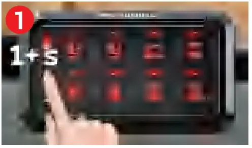
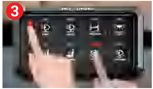
- MOMENTARY MODE:
- Long press the brightness adjustment button for 1 second.
When the red backlight flashes, it enters the Momentary setting state
- Press the button you want to set (you can choose between 8 or 12 buttons for Momentary Mode}, then press the ON/OFF button to confirm, now the setting is successful

- Press the ON/OFF button again to exit the setting mode

- Long press the brightness adjustment button for 1 second.
- STROBE MODE:
- Long press the brightness adjustment button for 1 second, and the red backlight flashes (note, this is the Momentary setting state, please refer to its specific steps)
- Then short press the brightness adjustment button.
When the blue backlight flashes, it enters the Strobe setting state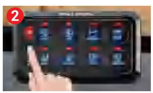
- Press the button you want to set (you can choose between 8 or 12 buttons for Strobe Mode}, then press the ON/OFF button to confirm, now the setting is successful
- Long press the brightness adjustment button for 1 second, and the red backlight flashes (note, this is the Momentary setting state, please refer to its specific steps)
 ON/OFF Switch with memory function, remember last setting automatically
 1.Short Press – 5-level brightness adjustment(] 00%, 75%, 50%, 25%, 10%}, Each time you press it, you switch the brightness to a different level
2.Long Press – Enter the setting mode, and choose between momentary mode and strobe mode, Long Press again to exit the setting mode- 1.Short Press – Switch single color (loop from 1-8 in order)
- .red
- orange
- yellow
- green
- cyan
- blue
- purple
- white
- 2. Long Press – Switch between Gradient/ Jump/ Breathing(loop from 9-11 in order)
9.Gradient: red-orange-yellow-green-cyan-blue-purple 1 a. Jump: red-orange-yellow-green-cyan-blue-purple
11.Breathing: red-orange-yellow-green-cyan-blue-purple
APP SETTING AND OPERATION
Scan the QR code to download MICTUNING App:
- Scan to download IOS APP
- Scan to download Google APP

Register account and login:

Connect Bluetooth Device:
- Search for device name “Pl C-2L-8″(for 8 Gang Panel) or “Pl C-2L-l 2″(for 12 Gang Panel) and connect
- Click on Switch Panel icon to start setting

Backlight Setting:

- Click on the Color Wheel to select the color you desire

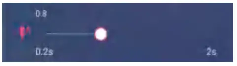
If you’d like the color switching effect, please click on the Color Changing Pattern or click” “to DIV your own effect
 - You may adjust the Brightness, Colors Switching Speed and Flashing Speed by dragging the sliders to the left/right

Control Mode Setting:
- By clicking on any button and selecting its control mode: Constant/Momentary/Strobe, you can set individual control mode for every button

- The Flashing Speed slider allows to adjust the strobing speed
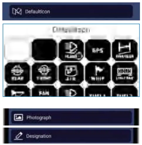
- Find the corresponding icon for a button, you can click on “Default icon” to select
FREQUENTLY ASKED QUESTIONS
What's the maximum operating current?
The 8 Gang Switch Panel is rated for GOA, and the 1 2 Gang Switch Panel is rated for 80A.
If connected to the battery and the power indicator light stays on, will it drain the battery?
No, it won't. The standby average current for this product is less than 3mA. A 60AH capacity battery can power the switch panel on standby for about 833 days without charging.
Can the ground wires be connected together?
Yes, they can be connected together.
How can I determine if the wiring is correct?
The power indicator light will turn red, indicating that the wiring is correct.
What is the purpose of the control box switch?
It changes the power source. It is recommended to use the power from the battery.
What is the specification for the ACC power relay?
It is the small-size power relay.
The app cannot find the device?
Step 1. Check the wiring to ensure it is properly connected. Step 2. For iPhones, try restarting your phone and enable app authorization and Bluetooth authorization in Privacy settings {Phone Settings - Privacy - Bluetooth - Allow the app to use Bluetooth). For Android devices, enable the location service and app location authorization to perform the search and connection in the app {The location function relates to privacy data, and MICTUNING assures that it won't collect such data; it is required due to physical layer regulations on Android devices).

Documents / Resources
 | MICTUNING P1s Gang Switch Panel with App Control [pdf] User Manual P1s Gang Switch Panel with App Control, P1s, Gang Switch Panel with App Control, Switch Panel with App Control, Panel with App Control, App Control, Control |