![]()
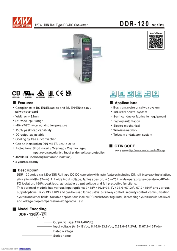
120W DIN Rail Type DC-DC Converter
DDR-120 series

User’s Manual

![]()
![]()
DDR-120A-12 120W DIN Rail Type DC-DC Converter
Features
- Compliance to BS EN/EN50155 and BS EN/EN45545-2 railway standard Width only 32mm
- 2:1 wide input range
- -40~+70C wide working temperature
- 150% peak load capability
- DC output adjustable
- Cooling by free air convection
- Can be installed on DIN rail TS-35/7.5 or 15
- Protections: Short circuit / Overload / Over voltage / Input reverse polarity / Input under voltage protection
- 4KVdc I/O isolation(Reinforced isolation)
- 3 years warranty
Applications
- Bus, tram, metro or railway system
- Industrial control system
- Semi-conductor fabrication equipment
- Factory automation
- Electro-mechanical
- Wireless network
- Telecom or datacom system
GTIN CODE
MW Search: https://www.meanwell.com/serviceGTIN.aspx
Description
DDR-120 series is a120W DIN Rail type DC-DC converter with main features including DIN rail-type easy installation, ultra slim width (32mm), 2:1 wide input voltage, fanless design, -40~+70 C wide operating temperature, 4KVdc I/O isolation, 150% peak load, adjustable output voltage and full protective functions.
This series of models has various input options: 9~18V/16.8~33.6V /33.6~67.2V /67.2~154V and various output options: 12V /24V/ 48V and can be used for industrial & railway control, security control, communication system and other fields. Suitable applications include DC buck/boost regulator, increasing system insulation level and voltage drop compensation along cable…etc.
Model Encoding

SPECIFICATION
| MODEL | DDR-120A-12 | DDR-120A-24 | DDR-120A-48 | DDR-12013-12 | DDR-120B-24 | DDR-120B-48 | |
| OUTPUT | DC VOLTAGE | 12V | 24V | 48V | 12V | 24V | 48V |
| RATED CURRENT | 8.3A | 4.2A | 2.1A | 10A | 5A | 2.5A | |
| CURRENT RANGE | 0 – 8.3A | 0 – 4.2A | 0 – 2.1A | 0 – 10A | 0 – 5A | 0 – 2.5A | |
| RATED POWER | 99.6W | 100.8W | 100.8W | 120W | 120W | 120W | |
| PEAK CURRENT | 12.45A | 6.3A | 3.15A | 15A | 7.5A | 3.75A | |
| PEAK POWER Notes | 150W (3sec.) | 180W (3sec.) | |||||
| RIPPLE 8 NOISE (max.) Note.2 | 50mVp-p | 50mVp-p | 50mVp-p | 50mVp-p | 50mVp-p | 50mVp-p | |
| VOLTAGE ADJ. RANGE | 9 – 14V | 24 – 28V | 48 – 56V | 9 – 14V | 24 – 28V | 48 – 56V | |
| VOLTAGE TOLERANCE Not..3 | ±1.0% | ±1.0% | ±1.0% | ±1.0% | ±1.0% | ±1.0% | |
| LINE REGULATION | ±0.5% | ±0.5% | ±0.5% | ±0.5% | ±0.5% | ±0.5% | |
| LOAD REGULATION | ±1.0% | ±1.0% | ±1.0% | ±1.0% | ±1.0% | ±1.0% | |
| SETUP, RISE TIME | 500ms, 60ms ©12Vdc | 500ms, 60ms @24Vdc | |||||
| HOLD UP TIME (Typ.) | Please refer to page 7 Hold up Time( Load de-rating curve ) | ||||||
| INPUT | VOLTAGE RANGE Note.4 | 9 – 18Vdc | 9 – 18Vdc | 9 – I8Vdc | 16.8 – 33.6Vdc | 16.8 – 33.6Vdc | 16.8 – 33.6Vdc |
| EFFICIENCY (Typ.) | 89.% | 89.% | 89.% | 89% | 90.% | 91% | |
| DC CURRENT (Typ.) | 11.2A ©12Vdc | 5.6A ©24Vdc | |||||
| INRUSH CURRENT (Typ.) | 5A ©12Vdc | 5A @ 24Vdc | |||||
| INTERRUPTION OF VOLTAGE SUPPLY | EN50155:2007-comply with 3ms© full load | EN50155:2007-compq with Siove! (6ms) @id bad. S2 level (10ms)ft 70% loac | |||||
| EN50155:2017-comply with S1 level | EN50155:2017-comply with Si level | ||||||
| PROTECTION | OVERLOAD | Normally works within 150% rated output power for more than 3 seconds and then constant current protection 105-135% rated output power with auto-recovery | |||||
| OVER VOLTAGE | 14.4 – 16.8V | I 28.8 – 33.6V | I 57.6 – 67.2V | 1 14.4 – 16.8V | I 28.8 – 33.6V | I 57.6 – 67.2V | |
| Protection type : Shut down o/p voltage, re power on to recover | |||||||
| REVERSE POLARITY | By internal MOSFET. no damage. recovers automatically after fault condition removed | ||||||
| UNDER VOLTAGE LOCKOUT | 1 2Vin (A – type) :Power ON?: 9V , OFFS:8.5V | I 24Vm (B – type) Power ON ;:-= 16.8V , OFF tt; 16.5V | |||||
| EIMRONNENI | WORKING TEMP. | -40 -+7012 (Refer to terating Curve’) | |||||
| WORKING HUMIDITY | 5 – 95% RH non-condensing | ||||||
| STORAGE TEMP., HUMIDITY | -40 – +85t , 5 – 95% RH non-condensing | ||||||
| TEMP. COEFFICIENT | ±0.03%/t (0- 55°C ) | ||||||
| VIBRATION | Component:10 – 500Hz. 5G 10minitcycle. 60min. each along X. Y, Z axes; Mounting: Compliance to IEC61373 | ||||||
| OPERATING ALTITUDE | 5000 meters | ||||||
| SAFETY & EMC (Note 6) | SAFETY STANDARDS | IEC 62368-1, UL 62368-1, EAC TP TC 004. AS/NZS 62368.1 approved; Design refer to UL508 | ||
| WITHSTAND VOLTAGE | 11P-0/P:4KVdc I/P-FG:2.5KVdc 0/P-FG:2.5KVdc | |||
| ISOLATION RESISTANCE | UP-0/P. UP-FG. 0/P-FG:>100M Ohms! 500Vdc / 25t / 70% RH | |||
| EMC EMISSION | Parameter | Standard | Test Level! Note | |
| Conducted | BS EN/EN55032 | Class B | ||
| Radiated | BS EN/EN55032 | Class 8 | ||
| Voltage Ricker | BS EN/EN61000-3-3 | — | ||
| Harmonic Current | —- | |||
| EMC IMMUNITY | BS EWEN55024 , BS EN/EN61000-6-2(BS EN/EN50082-2) | |||
| Parameter | Standard | Test Level! Note | ||
| ESD | BS EN/EN61000-4-2 | Level 3, 8KV air ; Level 3, 6KV contact; criteria A | ||
| Radiated | BS EN/EN61000-4-3 | Level 3, 10V/m ; criteria A | ||
| EFT / Burst | BS EN/EN61000-4-4 | Level 3, 2KV ; criteria A | ||
| Surge | BS EN/EN61000-4-5 | Level 3. 1KV/Line-Line level 3. 2KV/Line-Line-FG :criteria A | ||
| Conducted | BS EN/EN61000-4-6 | Level 3,10V ; criteria A | ||
| Magnetic Field | BS EN/EN61000-4-8 | Level 4. 30Alm ; criteria A | ||
| RAILWAY STANDARD | Compliance to BS EN/EN45545-2 for fire protection ; Meet BS EN/EN50155 / IEC60571 including IEC61373 for shock & vibration, BS EN/EN50121-3-2 for EMC (except for 9-18Vin) | |||
| OTHERS | MTBF | 1769.5K hrs min. Telcordia SR-332 (Bellcore) : 214.5K hrs min. MIL-HDBK-217F (25t ) | ||
| DIMENSION | 32’125.21102mm (WWI)) | |||
| PACKING | 510g; 28pcs/15.3Kg/1.22CUFT | |||
| NOTE | 1.All parameters NOT specially mentioned are measured at normal input (A:12Vdc , B:24Vdc) , rated load and 25t of ambient temperature. 2.Ripple & noise are measured at 20MHz of bandwidth by using a 12″ twisted pair-wire terminated with a 0.1 ri f & 47 rt f parallel capacitor. 3.Tolerance : includes set up tolerance, line regulation and load regulation. 4.Derating may be needed under low input voltage. Please check the derating curve for more details. 5.3 seconds max., please refer to peak loading curves. 6.The power supply is considered as an independent unit, but the final equipment still need to re-confirm that the whole system complies with the EMC directives. For guidance on how to perform these EMC tests, please refer to “EMI testing of component power supplies.” (as available on http://www.meanwell.com) 7.The ambient temperature derating of 3.5t /1000m with fanless models and of 5t /1000m with fan models for operating altitude higher than 2000m(6500ft). ※ Product Liability Disclaimer : For detailed information. please refer to https://www.meanwell.com/serviceDisclaimeraspx | |||
| MODEL | DDR-120C-12 | DDR-120C-24 | DDR-120C-48 | DDR-120D-12 | DDR-120D-24 | DDR-120D-48 | |
| OUTPUT | DC VOLTAGE | 12V | 24V | 48V | 12V | 24V | 48V |
| RATED CURRENT | 10A | 5A | 2.5A | 10A | 5A | 2.5A | |
| CURRENT RANGE | 0 – 10A | 0 – 5A | 0 – 2.5A | 0 – 10A | 0 – 5A | 0 – 2.5A | |
| RATED POWER | 120W | 120W | 120W | 120W | 120W | 120W | |
| PEAK CURRENT | 15A | 7.5A | 3.75A | 15A | 7.5A | 3.75A | |
| PEAK POWER Note.5 | 180W (3sec.) | ||||||
| RIPPLE & NOISE (max.) Note.2 | 50mVp-p | 50mVp-p | 50mVp-p | 50mVp-p | 50mVp-p | 50mVp-p | |
| VOLTAGE ADJ. RANGE | 9 – 14V | 24 – 28V | 48 – 56V | 9 – 14V | 24 – 28V | 48 – 56V | |
| VOLTAGE TOLERANCE Note.3 | ±1.0% | ±1.0% | ±1.0% | ±1.0% | ±1.0% | ±1.0% | |
| LINE REGULATION | ±0.5% | ±0.5% | ±0.5% | ±0.5% | ±0.5% | ±0.5% | |
| LOAD REGULATION | ±1.0% | ±1.0% | ±1.0% | ±1.0% | ±1.0% | ±1.0% | |
| SETUP, RISE TIME | 500ms, 60ms @48Vdc | 500ms, 60ms @110Vdc | |||||
| HOLD UP TIME (Typ.) | Please refer to page 7 Hold up Time( Load de-rating curve ) | ||||||
| INPUT | VOLTAGE RANGE Note.4 | 33.6 – 67.2Vdc | 33.6 – 67.2Vdc | 33.6 – 67.2Vdc | 67.2 – 154Vdc | 67.2 – 154Vdc | 67.2 – 154Vdc |
| EFFICIENCY (Typ.) | 90.% | 91% | 92% | 90.% | 91% | 92.% | |
| DC CURRENT (Typ.) | 2.8A @48Vdc | 1.3A @110Vdc | |||||
| INRUSH CURRENT (Typ.) | 5A@48Vdc | 5A@110Vdc | |||||
| INTERRUPTION OF VOLTAGE SUPPLY | EN50155:2007-comply with SI level (6ms) @ full load, S2 level (10ms) @ 60% load | EN50155:2007-comply with S2 level (10ms) @ full load | |||||
| EN50155:2017-comply with Si level | EN50155:2017-comply with 51 level | ||||||
| PROTECTION | OVERLOAD | Normally works within 150% rated output power for more than 3 seconds and then constant current protection 105-135% rated output power with auto-recovery | |||||
| OVER VOLTAGE | 14.4 – 16.8V | 1 28.8 – 33.6V | 157.6 – 67.2V | 1 14.4 -16.8V | I 28.8 – 33.6V | I 57.6 – 67.2V | |
| Protection type : Shut down o/p voltage, re power on to recover | |||||||
| REVERSE POLARITY | By internal MOSFET, no damage, recovers automatically after fault condition removed | ||||||
| UNDER VOLTAGE LOCKOUT | 48Vin (C-type):Power ON?-33.6V , OFF–.33V | 1110Vin(D-type):Power ON≥t67.2V,OFF≥65V | |||||
| ENVIRONMENT | WORKING TEMP. | -40 – +70°C (Refer to “Derating Curve”) | ||
| WORKING HUMIDITY | 5 – 95% RH non-condensing | |||
| STORAGE TEMP., HUMIDITY | -40 – +85t , 5 – 95% RH non-condensing | |||
| TEMP. COEFFICIENT | ±0.03%/°C (0 – 55°C ) | |||
| VIBRATION | Component:10 – 500Hz, 5G 10min./1cycle, 60min. each along X, Y, Z axes; Mounting: Compliance to IEC61373 | |||
| OPERATING ALTITUDE | 5000 meters | |||
| SAFETY & EMC (Note 6) | SAFETY STANDARDS | IEC 62368-1, UL 62368-1, EAC TP TC 004, AS/NZS 62368.1 approved; Design refer to UL508 | ||
| WITHSTAND VOLTAGE | I/P-0/P:4KVdc I!P-FG:2.5KVdc 0/P-FG:2.5KVdc | |||
| ISOLATION RESISTANCE | UP-0/P, UP-FG, 0/P-FG:>100M Ohms! 500Vdc / 25t/ 70% RH | |||
| EMC EMISSION | Parameter | Standard | Test Level I Note | |
| Conducted | BS EN1EN55032 | Class B | ||
| Radiated | BS EN1EN55032 | Class B | ||
| Voltage Flicker | BS ENIEN61000-3-3 | |||
| Harmonic Current | ||||
| EMC IMMUNITY | BS ENIEN55024 , BS EN1EN61000-6-2(BS EN1EN50082-2) | |||
| Parameter | Standard | Test Level I Note | ||
| ESD | BS ENIEN61000-4-2 | Level 3, 8KV air ; Level 3, 6KV contact; criteria A | ||
| Radiated | BS ENIEN61000-4-3 | Level 3, 10V/m ; criteria A | ||
| EFT I Burst | BS EN/EN61000-4-4 | Level 3, 2KV ; criteria A | ||
| Surge | BS EN/EN61000-4-5 | Level 3, 1KV/Line-Line ;Level 3, 2KVILine-Line-FG ;criteria A | ||
| Conducted | BS EN/EN61000-4-6 | Level 3, 10V ; criteria A | ||
| Magnetic Field | BS ENIEN61000-4-8 | Level 4, 30A/m ; criteria A | ||
| RAILWAY STANDARD | Compliance to BS EN1EN45545-2 for fire protection ; Meet BS EN/EN50155 l IEC60571 including IEC61373 for shock & vibration, BS EN/EN50121-3-2 for EMC | |||
| OTHERS | MTBF | 1769.5K hrs min. Telcordia SR-332 (Bellcore) ; 214.5K hrs min. MIL-HDBK-217F (25°C ) | ||
| DIMENSION | 32’125.2’102mm (WH’D) | |||
| PACKING | 510g; 28pcs/15.3Kg/1.22CUFT | |||
NOTE
- All parameters NOT specially mentioned are measured at normal input (C:48Vdc , D:110Vdc) , rated load and 25°C of ambient temperature.
- Ripple & noise are measured at 2OMHz of bandwidth by using a 12″ twisted pair-wire terminated with a 0.1 « f & 47 « f parallel capacitor.
- Tolerance : includes set up tolerance, line regulation and load regulation.
- Derating may be needed under low input voltage. Please check the derating curve for more details.
- 3 seconds max., please refer to peak loading curves.
- The power supply is considered as an independent unit, but the final equipment still need to re-confirm that the whole system complies with the EMC directives. For guidance on how to perform these EMC tests, please refer to “EMI testing of component power supplies.” (as available on http://www.meanwell.com)
- The ambient temperature derating of 3.5°C/1000m with fanless models and of 5°C/1000m with fan models for operating altitude higher than 2000m(6500ft).
※ Product Liability Disclaimer : For detailed information, please refer to https://www.meanwell.com/serviceDisclaimer.aspx
Block Diagram

Derating Curve

Output derating VS input voltage

Peak Loading

Input Fuse
There is a fuse connected in series to the positive input line, which is used to protect against abnormal surge. Fuse specifications of each model are shown as below.
| Type | Fuse Type | Reference and Rating |
| A | Time-Lag | Conquer MST, 8A, 250V *2 |
| B | Time-Lag | Conquer MST, 8A, 250V *1 |
| C | Time-Lag | Conquer MST, 4A, 250V *1 |
| D | Time-Lag | Conquer MST, 10A, 250V *2 |
Input Under-Voltage Protection
If input voltage drops below Vimin, the internal control IC shuts down and there is no output voltage. It recovers automatically when input voltage reaches above Vimin, please refer to the cruve below.

Input Reverse Polarity Protection
There is a MOSFET connected in series to the negative input line. If the input polarity is connected reversely, the MOSFET opens and there will be no output to protect the unit.
Input Range and Transient Ability
The series has a wide range input capability. With -30% / +40% of rated input voltage(except A Type), it can withstand that for 1 second.
Inrush Current
Inrush current is suppressed by a current limit circuit during the initial start-up, and then the circuit is bypassed by a MOSFET to reduce power consumption after accomplishing the start-up.

Hold-up Time
- EN50155: 2007 version – D type is in compliance with S2 level (10ms), while A types are in compliance with S1 level (3ms) at full load output condition. To fulfil the requirements of S2 level (10ms), B types require de-rating their output load to 70%, C types require de-rating their output load to 60%, please refer to the curve diagrams below.


- EN50155: 2017 version – Comply with S1 level (6ms)
Efficiency vs Load & Vin Curve
The efficiency vs load & Vin curves of each model are shown as below.


Immunity to Environmental Conditions
| Test method | Standard | Test conditions | Status |
| Cooling Test | EN 50155 section 12.2.3 (Column 2, Class TX) EN 60068-2-1 | Temperature: -40°C Dwell Time: 2 hrs/cycle | No damage |
| Dry Heat Test | EN 50155 section 12.2.4 (Column 2, Class TX) EN 50155 section 12.2.4 (Column 3, Class TX & Column 4, Class TX) EN 60068-2-2 | Temperature: 70°C 185°C Duration: 6 hrs / 10min | PASS |
| Damp Heat Test, Cyclic | EN 50155 section 12.2.5 EN 60068-2-30 | Temperature: 25°C-55°C Humidity: 90%-100% RH Duration: 48 hrs | PASS |
| Vibration Test | EN 50155 section 12.2.11 EN 61373 | Temperature: 19°C Humidity: 65% Duration: 10 mins | PASS |
| Increased Vibration Test | 112. EN 50155 section 12.2.11 EN 61373 | Temperature: 19°C Humidity: 65% Duration: 5 hrs | PASS |
| Shock Test | EN 50155 section 12.2.11 EN 61373 | Temperature: 21 ± 3°C Humidity: 65 ± 5% Duration: 30ms*18 | PASS |
| Low Temperature Storage Test | EN 50155 section 12.2.3 (Column 2, Class TX) EN 60068-2-1 | Temperature: -40°C Dwell Time: 16 hrs | PASS |
| Salt Mist Test | EN 50155 section 12.2.10 (Class ST4) | Temperature: 35°C ±2°C Duration: 96 hrs | PASS |
EN45545-2 Fire Test Conditions
| Test Items | Hazard Level | ||||
| Items | Standard | HL1 | HL2 | HL3 | |
| R22 | Oxygen index test | EN 45545-2:2013 EN ISO 4589-2:1996 | PASS | PASS | PASS |
| Smoke density test | EN 45545-2:2013 EN ISO 5659-2:2006 | PASS | PASS | PASS | |
| Smoke toxicity test | EN 45545-2:2013 NF X?0-100:2006 | PASS | PASS | PASS | |
| R24 | Oxygen index test | EN 45545-2:2013 EN ISO 4589-2:1996 | PASS | PASS | PASS |
| R25 | Glow-wire test | EN 45545-2:2013 EN 60695-2-11:2000 | PASS | PASS | PASS |
| R26 | Vertical flame test | EN 45545-2:2013 EN 60695-11:2003 | PASS | PASS | PASS |
Mechanical Specification


Installation Manual
Please refer to : http://www.meanwell.com/manual.html
Downloaded from Arrow.com.
File Name:DDR-120-SPEC 2022-03-18
Documents / Resources
 | MEAN WELL DDR-120A-12 120W DIN Rail Type DC-DC Converter [pdf] Owner's Manual DDR-120A-12, DDR-120A-12 120W DIN Rail Type DC-DC Converter, DIN Rail Type DC-DC Converter, DC-DC Converter, Converter, DDR-120A-24, DDR-120A-48, DDR-120B-12, DDR-120B-24, DDR-120B-48 |
 | MEAN WELL DDR-120A-12 120W DIN Rail Type DC-DC Converter [pdf] Owner's Manual DDR-120A-12 120W DIN Rail Type DC-DC Converter, DDR-120A-12, 120W DIN Rail Type DC-DC Converter, DIN Rail Type DC-DC Converter, Rail Type DC-DC Converter, DC-DC Converter, Converter |


