GARMIN GUID-62EBB282 Current Trolling Motor

Important Safety Information
WARNING
- See the Important Safety and Product Information guide in the product box for product warnings and other important information.
- Failure to install this device according to these instructions could result in personal injury, damage to the vessel or device, or poor product performance.
- Do not run the motor when the propeller is out of the water. Contact with the rotating propeller may result in severe injury.
- Do not use the motor in areas where you or other people in the water may come into contact with the rotating propeller, which could result in severe injury.
- Always disconnect the motor from the battery before handling or working with the propeller, propeller drive motor, electrical connections, or electronics enclosures to avoid serious injury or death.
CAUTION
- For the best possible performance and to avoid potential injury, damage to the device, or damage to your vessel, installation by a qualified marine installer is recommended.
- To avoid possible personal injury, always wear safety goggles, ear protection, and a dust mask when drilling, cutting, or sanding.
- When transporting the trolling motor, always use the handle on the back of the steering system housing and be mindful of the propeller drive motor and the propeller, to prevent the possibility of personal injury or property damage.
NOTICE
- When drilling or cutting, always check what is on the opposite side of the surface to avoid damaging the vessel.
- Due to the driving force generated by this product, not all kayaks can support it. Attempting to install or use the Force Current trolling motor on a kayak that cannot support it may damage the kayak. If in doubt, you should contact the kayak manufacturer for guidance before attempting to install the trolling motor on it.
Tools and Supplies Needed
- Drill
- #2 Phillips screwdriver
- Knife or scissors
- Lighter or matches
- Circuit breaker rated for continuous 40 A1
For installing the mount using bolts and nuts, you will also need:
- 8 mm (5/16 in.) drill bit, for drilling holes for bolts and nuts
• 11 mm (7/16 in.) combination wrench
• Sheet metal or other suitable material for reinforcing the mounting surface (optional) For installing jack nuts, you will also need:
• 11 mm (7/16 in.) drill bit
• 1/2 in. combination wrench
Checking the Propeller Clearance
WARNING
Before installing the trolling motor mount, you must make sure there will be enough clearance between the propeller and the hull through the entire rotation of the motor shaft. You must take into consideration potential flexing of the mounting location that may occur after the motor is installed. Installing the motor with insufficient space between the propeller and the hull may result in personal injury and property damage if the propeller contacts the hull during use.
- Rotate the propeller drive motor manually to check the clearance through a complete 360-degree rotation of the shaft.

NOTICE
You should check for sufficient clearance using both the high-efficiency propeller and the weedless propeller before installing the mount. - If necessary, reconsider the mounting location to ensure sufficient clearance between the propeller and the hull.
Installing the Mount
WARNING
Before installing the mount, you must make sure the mounting location provides adequate clearance between the propeller and the hull (Checking the Propeller Clearance, page 2).
NOTICE
Your kayak must have a flat stern on which to install the trolling motor mount. If your kayak does not have a flat stern, you must fabricate an adapter to conform to the shape of your kayak and provide a flat surface on which to install the mount. In such a case, we recommend contacting the kayak manufacturer for guidance and working with a qualified marine installer to ensure a safe and secure installation.
Select an option:
- If your kayak has threaded mounting holes on the stern, compatible with the Power-Pole® Micro anchor spike driver, you can use them to install the mount directly on your kayak (Installing the Mount on a Kayak with a Compatible Mounting Pattern, page 4).
- If your kayak does not have threaded mounting holes compatible with the Power-Pole Micro anchor spike driver, a suitable adapter plate for your kayak may be available from third-party manufacturers.
- If you have access to the space under the mounting surface, you can install the mount using bolts and nuts (Installing the Mount on a Kayak Without a Compatible Mounting Pattern, page 5).
Installing the Mount on a Kayak with a Compatible Mounting Pattern
- Measure the distance from the edge of the stern to the nearest mounting hole on the kayak.
- Select an option:
If the edge of the stern is less than 29 mm (1 1/8 in.) from the nearest mounting hole over the mounting holes directly on the kayak.
If the edge of the stern is between 29 mm (1 1/8 in.) and 100 mm (3 15/16 in.) from the nearest mounting hole 2 , add a 20 mm (3/4 in.) spacer between the mount and your kayak to ensure adequate clearance for the shape of the mount.
If the edge of the stern is more than 100 mm (3 15/16 in.) away from the nearest mounting hole, you cannot use the integrated mounting holes to install the mount.
An adapter plate may be available for your kayak to provide new mounting holes closer to the edge of the stern. If no adapter plate is available, you can drill new mounting holes in your kayak (Installing the Mount on a Kayak Without a Compatible Mounting Pattern, page 5). - Secure the mount to your kayak using the mounting screws and washers in bag A .

Installing the Mount on a Kayak Without a Compatible Mounting Pattern
You must have access to the space under the mounting surface in order to install the mount using the included nuts and bolts.
- Place the mount on the kayak stern and identify a suitable mounting location.
NOTE: The rear of the mount must overhang the stern, so that the mount is installed flat on the stern. - Mark the four pilot holes on the kayak.
- Using a 8 mm (5/16 in.) drill bit, drill the four mounting holes.
- Retrieve the bolts, nuts and fender washers from B bag and four plain washers from bag A .
- Secure the mount to the kayak using the bolts and plain washers on top of the mount, and the four fender washers and nuts on the underside of the mounting surface.

NOTICE
You must use washers on both sides of the mounting surface to reduce strain on the mounting surface material and ensure a secure installation. Installing the mount without using all washers may lead to damage to the motor and the kayak.
With some kayaks, it may be necessary to install a backing plate on one or both sides of the mounting surface to reinforce it, before installing the mount. If in doubt, contact the kayak manufacturer for specific guidance for your kayak model.
Installing the Motor on the Mount
CAUTION
When transporting the trolling motor, always use the handle on the back of the steering system housing and be mindful of the propeller drive motor and the propeller, to prevent the possibility of personal injury or property damage.
- If necessary, loosen the pivot knobs on both sides of the trolling motor.
- Lower the motor onto the mount at an approximately 45-degree angle, matching the pivot knobs on the motor with the pivot brackets on the mount.

- Allow the motor to pivot down to a vertical position.
- Tighten the knobs on either side of the motor until they stop.
Installing the Locking Pin
The Force Current trolling motor supports three different positions for the locking pin, intended to offset the angle of the stern relative to the water.
- Insert the locking pin 1 through the clevis on both sides of the motor.

- Install the cotter ring 2 on the end of the locking pin to secure it in place.
- When you deploy the motor, the mount latch catches the locking pin, securing the motor in the deployed position.
- You should examine the angle of the shaft relative to the kayak, and move the locking pin to one of the other two positions, if necessary, to set the motor shaft at a perpendicular angle to the water surface.
Installing the Pull Rope
- Feed one end of the rope through the metallic release latch in the mount 1 .
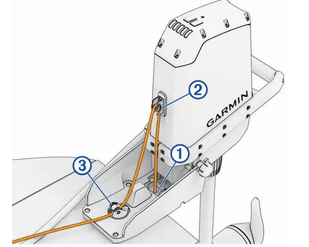
- Tie the end of the rope under the mount into a stopper knot to prevent the rope from pulling out through the release latch.

- Feed the rope up through the eyelet on the front of the motor 2 .
- Guide the rope down and feed it through the swivel pulley on the mount 3 .
- Select a mounting location for the rope cleat 4 just in front of the seat and off to one side.

- Select mounting points for the pad eyes 5 , which guide the rope from the mount to the cleat.
- Install the pad eyes and the cleat (Installing the Pad Eyes and Cleat, page 9).
- Route the rope through the pad eyes and the cleat.
- Install the rope handle (Installing the Rope Handle, page 11).
Installing the Pad Eyes and Cleat
If your kayak is equipped with a track system or threaded inserts, we recommend using them to install the pad eyes and the rope cleat, if possible. The pad eyes and the cleat are packaged with a set of T-nuts for mounting them onto a standard T-track. If a T-track or threaded insert is not available, follow these steps to install the pad eyes or the cleat using the included jack nuts and screws.
- Using an 11 mm (7/16 in.) drill bit, drill the mounting holes.
- Install a jack nut in each mounting hole (Installing Jack Nuts, page 10).
- Secure the cleat or pad eye to your kayak using the included mounting screws.
NOTE: You must secure the cleat to your kayak using two screws. Make sure you install the cleat in the correct orientation, with the pulley facing the bow of your kayak, which enables you to pull the rope back toward the stern to stow the motor.
Installing Jack Nuts
The Force Current trolling motor is packaged with hardware that can be used to install the included 1/4 in.–20 jack nuts using common tools. If preferred, you can purchase a specialized jack nut installation tool. When using a specialized tool, you should follow the tool manufacturer’s instructions for installing jack nuts.
NOTICE
The included jack nuts are intended for mounting surfaces between 0.020 and 0.190 in. thick. If the mounting surface thickness is outside that range, you must purchase appropriate jack nuts to ensure a secure installation and avoid the possibility of damage to the kayak.
- Retrieve the coupling nut, screw, and washer from bag G .
- Thread the screw through the coupling nut, the washer, and the jack nut.

- Insert the jack nut and screw through the hole in the mounting surface until the flange on the jack nut is flat against the surface.
- Position a 1/2 in. wrench on the coupling nut.
- While maintaining downward pressure on the head of the screw to keep it from rotating, turn the coupling nut clockwise using the wrench.

As you tighten the coupling nut down, the screw is pulled up, causing the jack nut to collapse under the mounting surface. - Continue turning the coupling nut until it stops.
The jack nut is fully collapsed and secure in the mounting surface. - While holding the screw in place using the #2 Phillips screwdriver, turn the coupling nut counterclockwise to loosen it.
- Using a #2 Phillips screwdriver, remove the screw and the coupling nut from the jack nut.
Installing the Rope Handle
- Feed the end of the rope through the two pieces of the pull handle.
- Trim the rope, allowing enough slack to make sure you can comfortably reach it from your position seated in your kayak.
TIP: We recommend trimming the rope to about 20 cm (8 in.) from the cleat, so the pull handle will stay close to the cleat when the motor is in the deployed position. - Tie a stopper knot to bind the rope inside the pull handle.
- If necessary, trim and melt the end of the rope to prevent fraying.
- Snap the two pieces of the pull handle together.

Installing the Skeg
NOTICE
You must install the skeg to help protect the propeller from damage if the propeller drive motor collides with an underwater obstacle.
- Place the skeg over the fin on the bottom of the propeller drive motor, starting from the front.

- Using a 3 mm hex key (included), install the screw and washer to secure the skeg.
Installing the Propeller
The Force Current trolling motor is packaged with a weedless propeller and a high-efficiency propeller. The weedless propeller is designed to help prevent weeds from wrapping around the propeller and the shaft.
NOTICE
You should use the Force Current trolling motor with the high-efficiency propeller only in open-water conditions. When using the high-efficiency propeller in shallow water conditions, there is an increased risk of damaging the propeller if the motor collides with an underwater obstacle.
- Insert the pin 1 through the propeller motor shaft.

- If necessary, rotate the motor shaft to orient the pin horizontally so it is less likely to fall out during installation.
- Align the channel on the inside of the propeller with the pin, and slide the propeller onto the motor shaft.
- Place the anode 2 , washer 3 , lock washer 4 , and nut 5 onto the end of the motor shaft.
- Using a 9/16 in. (14 mm) socket, tighten the lock nut to 16.27 N-m (12 lbf-ft.) to secure the propeller.
Installing the Remote Control Cradle
- Using the cradle as a template, mark the two pilot holes.
- Remove the cradle from the mounting surface and drill the pilot holes.
NOTICE
Do not drill through the cradle when drilling the pilot holes because this may damage the cradle. - Secure the cradle to the mounting surface using the included screws.
Connecting to Power
WARNING
To avoid possible serious personal injury or property damage, the circuit breaker must be in the off position before you connect the trolling motor power cable to it.
You must connect the positive (+) wire on the power cable through a circuit breaker or a fuse rated for 40 A
(continuous). Connecting this wire to power without a circuit breaker or fuse could result in a short on the wire, which may lead to overheating and a possible fire.
NOTICE
You must connect the Force Current trolling motor to a 12 or 24 Vdc battery. Connecting the motor to other voltages may cause poor performance or product damage.
- Connect the trolling motor power cable to the battery, routing the red (+) wire through a circuit breaker rated for 40 A (continuous).
- Turn the weather cap on the trolling motor power connector a quarter-turn counterclockwise to expose the power connector.
- Insert the power cable connector, with the cable approximately parallel to the kayak, and push until it is fully inserted.
NOTE: Make sure the locking collar on the power cable connector is in the unlock position, before connecting it to the motor.
The power cable strain relief rests against the cradle on the motor housing. - Turn the locking ring on the power cable connector a quarter-turn clockwise to lock it in place.
Power Steer Foot Pedals
The Power Steer Foot Pedals are an optional accessory included with some models.
Installation Options
NOTICE
Although the installation methods described in this manual cover a variety of kayak models, your kayak may demand an installation method that is not addressed here. If you have any doubt about how these instructions apply to your kayak, you should contact the kayak manufacturer for guidance on the best way to install the Power Steer foot pedal rails on your model.
- If your kayak is equipped with compatible T-tracks on the gunwales, you can install the rails using screws and T- nuts (Installing the Rails on T-tracks, page 17).
- If your kayak is equipped with a set of pedal rails or suitable threaded inserts on the sides of the deck, you may be able to install the rails using the existing mounting holes (Installing the Rails Using Existing Mounting Holes, page 18).
- If your kayak is not equipped with a T-track or other available anchor points, you can install the rails using jack nuts (Installing the Rails Using Jack Nuts, page 18).
Pedal Height Configuration
The pedal rails are arranged out-of-the-box to support the pedals in a high position, due to the off-center placement of the mounting point on the pedal carriages. You can reverse the pedal rails for a lower pedal position.

NOTICE
You should always install the rails with the pedal carriage button toward the stern of the kayak, so you can easily reach it to adjust the pedal distance while seated.
NOTE: When reversing the pedal rails in a gunwale-mounted installation, you must remove the pre-installed right-angle adapters from the rails and reinstall them according to the reversed orientation (Removing the Right-Angle Adapter, page 15).
Removing the Right-Angle Adapter
The pre-installed right-angle adapter allows you to mount the rails on the gunwales of your kayak. To install the rails on the sides of the deck, you must remove the right-angle adapter from the rails.

Remove the two screws securing the right-angle adapter to the rails.
Installing the Stabilizers
The optional stabilizers are designed to support the pedal rails against the deck, to reduce strain on the pedal rail mounting surface.
If you plan to use the stabilizers, you must attach them to the rails before installing the rails on your kayak.
- Connect the fixed part of the stabilizer 1 to one of the adjustable legs 2 found in the hardware bag, using the two knobs and the nut from the bag labeled F .

The stabilizer is packaged with a long and a short adjustable leg. You should choose the option that ensures the assembled stabilizer can reach the deck to support the rails. - Slide the assembled stabilizer onto the end of the rail opposite to the button on the pedal carriage.

NOTE: You may need to temporarily remove the right-angle adapter to install the stabilizer (Removing the Right-Angle Adapter, page 15). - Hold the button on the stabilizer while you slide it into the desired position.
- Loosen the knobs on the stabilizer.
- Extend the adjustable leg until it touches the deck, and tighten the knobs again.
- Repeat steps 1 through 5 to install the stabilizer on the other set of rails.
Installing the Rails on T-tracks
NOTICE
The included screws and T-nuts may not be suitable for all kayak track systems. You must use the correct hardware for your kayak’s track system. Installing the rails using hardware that is not appropriate for your track system may damage to your kayak or the pedal rails.
- If necessary, install the stabilizer on the rails on one side of your kayak (Installing the Stabilizers, page 16).
- Retrieve the screws from bag E , and the T-nuts and washers from bag .
- Slide two T-nuts in from the ends of the track until they align with the mounting holes on the right-angle adapter on the rails.
- Install the rails on the track using the screws and washers.

- Make sure there is no gap between the rails and the side of the deck, and tighten the screws.
NOTICE
You must ensure maximum contact between the kayak and the right-angle adapter. Leaving a gap between the rails and the sides of the deck results in a less stable installation and may cause damage to the kayak. - Repeat this procedure for the other side of your kayak.
Installing the Rails Using Existing Mounting Holes
Before installing the rails on the sides of the deck, you must remove the right-angle adapter from the rails (Removing the Right-Angle Adapter, page 15).
The Power Steer foot pedals are packaged with 1/4 in.–20 screws in bag E and washers in bag D , intended for mounting the rails to the sides of the deck. The included hardware may be incompatible with existing mounting holes on your kayak. If you are replacing an existing set of rails, you should consider reusing the original mounting hardware to install the new rails.
NOTICE
You must use screws and washers that are appropriate for the pedal rails and for the mounting holes on your kayak. Installing the rails without the appropriate hardware may damage the rails and your kayak.
- If necessary, remove the existing set of rails from your kayak, and set the mounting hardware aside.
- Install the rails on the sides of the deck using screws and washers.

NOTICE
You must use washers to install the rails. Installing the rails without washers may damage the rails or your kayak.
Installing the Rails Using Jack Nuts
Before installing the rails on the sides of the deck, you must remove the right-angle adapter from the rails (Removing the Right-Angle Adapter, page 15).
If your kayak is not equipped with a track system or suitable mounting points for the pedal rails, you can install the needed mounting points using the included jack nuts.
- Using a pedal rail as a template, mark the pilot holes on one side of your kayak.
- Using an 11 mm (7/16 in.) drill bit, drill the mounting holes.
NOTICE
Do not drill mounting holes through the rails. Drilling the mounting holes through the rails may damage the rails. - Install a jack nut from bag E in each mounting hole (Installing Jack Nuts, page 10).
- Secure the rails to the kayak using the screws from bag E and the washers from bag D .
- Repeat this procedure for the other side of your kayak.
Attaching the Pedals to the Rails
- Align the screw on the outside of the pedal with the threaded socket in the pedal carriage on the rail, and turn the knob on the other side of the pedal, clockwise, to attach the pedal to the pedal carriage.

- Tilt the pedal back and forth to check its range of motion, and adjust the angle of the pedal if necessary.
- If necessary, push the button on the pedal carriage and slide it along the rail to position the pedal at a comfortable distance.

NOTICE
Do not move the pedal carriages all the way to either end of the pedal rail. If the pedal carriage overlaps one of the pedal rail mounting screws, it may become difficult to move it. - Repeat the steps for the other pedal.
TIP: You can check the marks where the pedals connect to the pedal carriages to make sure both pedals are installed at the same angle.
NOTICE
You must remove the pedals from the pedal carriages before transporting the kayak. The pedals may become loose during transport, which could cause property damage.
Specifications
Trolling Motor
| Weight | Motor only: 10.1 kg (22.2 lbs)
With mount and cable: 12.6 kg (27.8 lbs) |
| Operating temperature | From -5° to 40°C (from 32° to 104°F) |
| Storage temperature | From -40° to 85°C (-40° to 185°F) |
| Water rating | Steering system housing: IEC 60529 IPX72 Propeller drive motor housing: IEC 60529 IPX83 |
| Power cable length | 165 cm (5 ft. 5 in.) |
| Input voltage | From 12 to 24 Vdc |
| Input amperage | 40 A continuous |
| Breaker (not included) | 32 VDC or greater, suitable for 40 A continuous
NOTE: You can protect the system by using a larger circuit breaker, not to exceed 60 A, if you are operating under high temperatures or if you are sharing the circuit with other devices. You should verify that your boat wiring meets marine wiring standards using a larger breaker before changing it. |
| Maximum power consump tion | 420 W @ 12 Vdc
768 W @ 24 Vdc |
| Wireless frequency and transmit power | 2.4 GHz @ 19.0 dBm maximum |
Dimensions

| 1 | 431 mm (17 in.) |
| 2 | 29 mm (1 1/8 in.) |
| 3 | 290 mm (11 3/8 in.) min.
422 mm (16 5/8 in.) max. |
| 4 | 470 mm (18 1/2 in.) min.
602 mm (23 3/4 in.) max. |

| 5 | 527 mm (20 3/4 in.) |
| 6 | 185 mm (7 5/16 in.) |

| 7 | 1005 mm (39 5/8 in.) |
| 8 | 385 mm (15 3/16 in.) |
| 9 | 112 mm (4 3/8 in.) |
Power Steer Foot Pedals
The Power Steer foot pedals are only included with some models.
| Weight (complete system, including rails) | 3.08 kg (6.8 lb.) |
| Operating temperature | From -5° to 40°C (from 32° to 104°F) |
| Storage temperature | From -40° to 85°C (-40° to 185°F) |
| Water rating | IEC 60529 IPX74 |
| Power Supply | 2 AA batteries per pedal |
| Wireless frequency and transmit power | 2.4 GHz @ 9.1 dBm maximum |
Dimensions
| 1 | 394 mm (15 1/2 in.) |
| 2 | 87 mm (3 7/16 in.) minimum (short stabilizer arm) 196 mm (7 11/16 in.) maximum (long stabilizer arm) |
| 3 | 32 mm (1 1/4 in.) |

| 4 | 141 mm (5 9/16 in.) |
| 5 | 21 mm (13/16 in.) |

Remote Control
| Dimensions (W×H×D) | 152 x 52 x 32 mm (6 x 2 x 11/4 in.) |
| Weight | 109 g (3.8 oz.) without batteries |
| Material | Glass-filled nylon |
| Display type | Sunlight-visible, transflective memory-in-pixel (MIP) |
| Display resolution | R240 x 240 pixels |
| Display size (diameter) | 30.2 mm (13/16 in.) |
| Operating temperature | From -15° to 55°C (5° to 131°F) |
| Storage temperature | From -40° to 85°C (-40° to 185°F) |
| Battery type | 2 AA (not included) |
| Battery life | 240 hr., typical use |
| Radio frequency | 2.4 GHz @ 10.0 dBm nominal |
| Water rating | IEC 60529 IPX75 |
| Compass-safe distance | 15 cm (6 in.) |
NBTC SDoC
© 2025 Garmin Ltd. or its subsidiaries
Garmin®, the Garmin logo, ActiveCaptain®, and Force® are trademarks of Garmin Ltd. or its subsidiaries, registered in the USA and other countries. These trademarks may not be used without the express permission of Garmin.
You should reference United States Code of Federal Regulations: 33 CFR 183 – Boats and Associated Equipment and ABYC E-11: AC and DC Electrical Systems on Boats when installing this trolling motor.
FAQ
Do I need to use washers while installing the mount?
Yes, it is essential to use washers on both sides of the mounting surface to reduce strain and ensure a secure installation. Failure to do so may result in damage to the motor and kayak.
What should I do if my kayak does not have a flat stern?
If your kayak does not have a flat stern, you will need to fabricate an adapter to conform to the shape of your kayak. Contact the kayak manufacturer for guidance and consider working with a qualified marine installer for a safe installation.
Documents / Resources
 |
GARMIN GUID-62EBB282 Current Trolling Motor [pdf] Installation Guide GUID-62EBB282 Current Trolling Motor, GUID-62EBB282, Current Trolling Motor, Trolling Motor |