![]()
30A/40A
Solar Charge Controller
PRODUCT MANUAL
Maximum Power Point Tracking (MPPT) (12V/24V)

30A, 40A MPPT Solar Charge Controller
 https://www.litime.com/pages/register-warranty/?utm_source=LT&utm_medium=manual&utm_campaign=warranty https://www.litime.com/pages/register-warranty/?utm_source=LT&utm_medium=manual&utm_campaign=warranty | UNITED STATES |
IMPORTANT SAFETY INSTRUCTIONS
Please read the following safety instructions carefully and perform installation and connection operations under the guidance of professionals. This manual contains important safety, installation, and operational instructions for the MPPT solar charge controller.
GENERAL SAFETY INFORMATION
- Read all cautionary and safety instructions in this manual before installation. If an operation needs to be done, be sure to use insulation tools and keep hands dry.
- There are no parts inside the controller that require maintenance or repair, DO NOT disassemble and try to repair the controller by yourself.
- Install the controller at a place with good ventilation conditions as the radiator may reach a very high temperature during operation.
- After installation, check whether all wiring connections are tight and reliable to avoid the danger of heat accumulation caused by loose connections.
BATTERY SAFETY
- Carefully read battery manuals, and operate the battery according to the battery manufacturer’s guidance.
- Be very careful when installing lead-acid batteries. Wear eye protection and have fresh water available in case there is contact with the battery acid.
- Explosive battery gases may be present while charging a lead-acid battery. Make sure there is enough ventilation to release the gases.
- Keep the lead-acid battery away from fire sparks, as it may produce flammable gas.
- Please set the correct battery type for the first use.
CHARGE CONTROLLER SAFETY
- Please completely cover/cap the solar panels during installation to avoid generating current.
- If grounding is required, please make sure to ground the device on the negative.
- Please DO NOT reverse connect battery wires to the battery ports.
WARNING
- NEVER connect the solar panel array to the controller without a battery. The battery must be connected first.
- Ensure input voltage does not exceed 100 VDC to prevent permanent damage.
PRODUCT OVERVIEW
12V/24V 30A/40A MPPT SOLAR CHARGE CONTROLLER
| Default Battery Setting | 12V LI (Lithium Iron Phosphate) Battery | |
| System Voltage | 12V/24V | |
| Rated Charging Current | 30A | 40A |
| Rated Load Current | 20A | |
| Max. Solar Panel System Input Power | 450W for 12V/900W for 24V | 600W for 12V/1200W for 24V |

ADDITIONAL COMPONENTS
REMOTE TEMPERATURE SENSOR / MAGIC STICKER
For lithium batteries, the sensor measures the surrounding tempera-ture for Low Temperature Charging Protection (LTCP).
For lead-acid batteries, the sensor measures the surrounding temperature for precise temperature compensation.

 | Mounting Brackets | 4pcs |
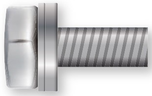 | M8 Screws for Fixing Brackets to Controller | 4pcs |
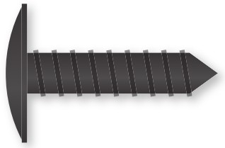 | Screws for Fixing Brackets to Wood Wall | 4pcs |
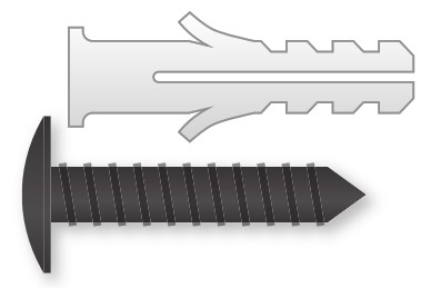 | Screws & Plastic Anchors for Fixing Brackets to Drywall | 4pcs for each |
 | Copper Wire Connectors | 6pcs |
 | Heat Shrink Tubes | 6pcs |
BLUETOOTH INSTALLATION AND OPERATION
APP DOWNLOAD
The MPPT controller is equipped with a built-in Bluetooth module that can be monitored and controlled via the APP available on the Apple APP Store and Google Play.

APP OPERATION
Scan for Bluetooth APP operating instructions and full version manual.

https://www.litime.com/pages/mppt-controller-bluetooth-installation-and-operation?utm_source=Brand&utm_medium=User+Manual
Upon registering the account, you can reset the password by tapping the ![]() in the top left corner of the APP. (Initial password: 0000)
in the top left corner of the APP. (Initial password: 0000)
Note: The password is required for adjusting the parameters in the “Parameter Settings” interface.
![]()
FCC STATEMENT
(FCC ID:2BDSV-M2430N)
This device complies with Part 15 of the FCC Rules. Operation is subject to the following two conditions:
• This device may not cause harmful interference.
• This device must accept any interference received, including interfer-ence that may cause undesired operation.
This device has been tested and found to comply with the limits for a Class B digital device, pursuant to Part 15 of the FCC Rules. These limits are designed to provide reasonable protection against harmful interfer-ence in a residential installation. This device generates, uses, and can radiate radio frequency energy and, if not installed and used in accor-dance with the instructions, may cause harmful interference to radio communications. However, there is no guarantee that interference will not occur in a particular installation. If this device does cause harmful interference to radio or television reception, which can be determined by turning the equipment off and on, the user is encouraged to try to correct the interference by one or more of the following measures:
- Orient or relocate the receiving antenna.
- Increase the separation between the equipment and receiver.
- Connect the equipment into an outlet on a circuit different from that to which the receiver is connected.
- Consult the dealer or an experienced radio/TV technician for help.
- To maintain compliance with FCC’s RF Exposure guidelines, This equipment should be installed and operated with minimum 20cm distance between the radiator and your b ody: Use only the supplied antenna.
IC STATEMENT
(IC ID: 32466-M2430N)
This device complies with Industry Canada licence-exempt RSS standard(s). Operation is subject to the following two conditions: This device may not cause interference. This device must accept any interference, including interference that may cause undesired operation of the device.
RF Exposure Information The device has been evaluated to meet general RF exposure requirement. The device can be used in portable/moblie exposure condition without restriction.
IDENTIFICATION OF PARTS

| 1 LCD Screen 2 Operating Keys 3 LED Indicators (Solar/BAT/DC Load/FAULT) 4 Remote Temperature Sensor Port | 5 Solar Panel Terminals 6 Battery Terminals 7 DC Load Terminals 8 RS485 Communication Port (RJ12) 9 Mounting Holes |
INSTALLATION
Never install the controller in a sealed enclosure with flooded batteries. Gas can accumulate and there is a risk of explosion.
CHOOSE THE MOUNTING LOCATION
Choose a vertical surface protected from direct sunlight, high temperatures, and water. Make sure there is good ventilation.
Check the ventilation clearance above the controller for at least 3.94″ (100mm) and below the controller for at least 7.87″ (200mm).

INSTALLATION METHOD 1 USING MOUNTING HOLE


INSTALLATION METHOD 2 USING MOUNTING BRACKETS


WIRING
- We strongly recommend that fuses or breakers be connected at the solar panel array side, load side, and battery side so as to avoid electric shock during wiring operation or faulty operations, and make sure the fuses and breakers are in an open state before wiring.
- DO NOT connect any inverters, AC Loads, or battery chargers to the LOAD Ports of the charge controller.
- Do not over-tighten the screw terminals. This could potentially break the piece that holds the wire to the charge controller.
WIRE GAUGE RECOMMENDATION
| Model | 30A | 40A |
| Solar Panel / Battery | 8 AWG | 7 AWG |
| Load | 10 AWG | |
| Max. Wire Gauge | 8 AWG | 7 AWG |
FUSE RECOMMENDATION
(1.2 TO 1.5 TIMES THE MAXIMUM CONTINUOUS CURRENT)
| Model | 30A | 40A |
| Solar Panel / Battery | 36A to 45A | 48A to 60A |
| Load | 24A to 30A | |
WIRING SEQUENCE AND REFERENCE CONNECTION DIAGRAM
- Wear insulating gloves before the operation to prevent safety accidents.
- Loosen screws and wiring terminals counterclockwise and tighten clockwise. The wire connector needs to be placed on the wiring terminal.
- Connect the devices to the controller,
 to,
to,  to ,
to , - Always connect the negative terminal first and then the positive
Complete the installation according to the following con-nection sequence, ![]() to
to![]() ,
,![]() to
to![]()
① Battery ![]() ② DC Load (Optional)
② DC Load (Optional) ![]() ③ Solar Panel
③ Solar Panel ![]() ④ Communication Port (Optional)
④ Communication Port (Optional) ![]() ⑤ Remote Temp. Sensor (Optional)
⑤ Remote Temp. Sensor (Optional)
REFERENCE CONNECTION DIAGRAM

OPERATION
The controller comes equipped with an LCD screen and 4 buttons to operate the menus.
- Please set the correct battery type for the first use if it is not a 12V lithium battery as the default setting.
STARTUP INTERFACE
During startup, the 4 LED indicators will first flash successively, and after self-inspection, the LCD screen starts and displays the main interface.
LCD DISPLAY
Main Interface
The main interface displays the battery’s voltage after starting up, and the system is set to 12V LiFePO4 battery mode by default.

![]() If the connected battery is not a 12V LiFePO4 battery, the controller will display error code E01 or E02. Changing to the correct system settings will allow the controller to function normally
If the connected battery is not a 12V LiFePO4 battery, the controller will display error code E01 or E02. Changing to the correct system settings will allow the controller to function normally
LCD INDICATORS

KEY OPERATIONS
In View Mode
| Key | Operation | Function |
| Long Press | Enter Set Mode | |
| Short Press | View Previous Page | |
| View Next Page | ||
| DC Load On/OFF (Load Mode 15 Only) |
In Set Mode
| Key | Operation | Function |
| Long Press | Save Data & Exit Set Mode | |
| Short Press | Next | |
| Short Press | Increase Value | |
| Decrease Value | ||
| Exit Set Mode without Saving |
SWITCHING OF DISPLAYED INFORMATION
The information displayed on the LCD interface in View Mode can be changed by short pressing the (UP) or (DOWN) key.
PROGRAMMING SYSTEM VOLTAGE
Step 1 Enter the Setting
Long press (SET) in View Mode / any View page.

Step 2 Set the Battery Voltage
Short press (SET) again to enter the system voltage setting, short press the (UP) or (DOWN) to cycle through the battery voltage, then long press the (SET) key to complete the selection

![]() Note: Selecting LI (LiFePO4) battery type requires locking the battery system voltage and cannot be selected for “AUTO” mode (automatic recognition of system voltage).
Note: Selecting LI (LiFePO4) battery type requires locking the battery system voltage and cannot be selected for “AUTO” mode (automatic recognition of system voltage).
PROGRAMMING LOAD MODE
The default load mode is the “Manual Mode” of code (15) (see “Load Modes Introduction” for details). The load mode adjustment method is as follows.
“Manual Mode” Operation
Only when the load mode is the “Manual Mode” of code (15), the manual operation to turn on or off the load is valid.
Operation Method: Short press the (RETURN) button in any main interface to turn on or off the load.
Load Modes Introduction
| Code | Definition | Description |
| Daylight Auto-Control | DC load turns on when no daylight is detected. | |
| 1-14 | Daylight On/ Timer Off | DC load turns on when no daylight is detected. DC load turns off according to timer. 1-14 indicates Timer setting hours. |
| 15 | Manual Mode | DC load can be turned on/off by pressing the [RETURN] button. |
| 16 | Testing Mode | DC load turns on and off in a quick succession. |
| 17 | Always On | DC load will be on for 24 hours a day. |
![]() Note: For load modes 1-14, the number means the load lasting time, e.g., “1” means the load would turn off in 1 hour after turning on, and “8” means off in 8 hours. Please notice that the detection of sunlight would turn off the load for all load modes 1-14, even if the timer hasn’t run out yet.
Note: For load modes 1-14, the number means the load lasting time, e.g., “1” means the load would turn off in 1 hour after turning on, and “8” means off in 8 hours. Please notice that the detection of sunlight would turn off the load for all load modes 1-14, even if the timer hasn’t run out yet.
LED INDICATORS
 | SOLAR Indicator | Indicating the controller’s current charging state. |
 | BAT Indicator | Indicating the battery’s current state. |
 | DC LOAD Indicator | Indicating the loads’ on / off and state. |
 | FAULT Indicator | Indicating whether the controller is functioning normally. |
| LED | Status | Description |
| SOLAR | Off | No Solar Input *PV LED is generally off during nighttime. |
| Double Flash | Solar Input Detected | |
| Single Flash | Reverse Polarities Detected | |
| Steady On | Solar Input Steady | |
| Slow Flash | In Equalize/Boost/Float Charge | |
| BAT | Single Flash | Reverse Polarities Detected |
| Fast Flash | Battery Over Voltage | |
| Slow Flash | Battery Over Discharged | |
| Steady On | Battery On | |
| DC LOAD | Off | Load Off |
| Fast Flash | DC Load Short Circuit / Overloading | |
| Steady On | DC Load On | |
| FAULT | Off | No Errors |
| Steady On | System Error Detected |
SPECIFICATIONS
| Parameter | Value |
|---|---|
| System Voltage | 12V / 24V / Auto |
| No-Load Loss | 12mA at 12V / 10mA at 24V |
| Battery Voltage | 9V to 32V |
| Max. Solar Input Voltage | 100V |
| Max. Power Point Voltage Range | Battery Voltage + 3V to 76V |
| Rated Charging Current | 30A / 40A |
| Rated Load Current | 20A |
| Max. Solar Panel System Input Power | 450W for 12V / 900W for 24V (30A) 600W for 12V / 1200W for 24V (40A) |
| Conversion Efficiency | ≤97% |
| MPPT Tracking Efficiency | 99.9% |
| Temperature Compensation Factor | 12V: -10mV/+1°F (-18mV/+1°C) 24V: -20mV/+1°F (-36mV/+1°C) |
| Operating Temperature | -31°F to 113°F / -35°C to 45°C |
| Low Temperature Charging Protection (LTCP) | Yes |
| Protection Class | IP32 |
| Weight | 4.41lb / 2kg |
| Communication Method | RS485 (RJ12) / Inbuilt BT |
| Altitude | ≤3000m |
| Dimensions | L9.65W7.09H3.25 inch / L245W180H82.5 mm |
①Selecting LI (LiFePO4) battery type requires locking the battery system voltage and cannot be selected for “AUTO” mode (automatic recognition of system voltage).
② This product supports Low Temperature Charging Protection (LTCP) for lithium batteries, where the controller stops battery charging when the environment temperature falls below 0°C/32°F and resumes charging when the temperature rises above 5°C/41°F. This function is off by default. Turn it on via the “LiTime Solar” APP or press the Key on the controller to set it. (Make sure the temperature sensor is connected to the controller).
TROUBLESHOOTING
| Error Code | Error | Solution |
|---|---|---|
| E00 | No Error | System is working normally. |
| E01 | Battery Over-discharged | The battery voltage is too low. DC load will be turned off until the battery re-charges to recovery voltage. |
| E02 | Battery Over-voltage | The battery voltage has exceeded the controller limit. Check battery bank voltage for compatibility with the controller. |
| E04 | Load Short Circuit | DC load short circuit. Disconnect the load and check if the rated current of the load is less than 20A. |
| E05 | Load Overloading | DC load power draw exceeds controller capability. Reduce load size or upgrade to a controller with higher DC load capacity. |
| E06 | Overheating | The controller exceeds the operating temperature limit. Ensure the controller is placed in a well-ventilated, cool, dry place. |
| E07 | Environmental Over-temperature | The environment temperature detected by the external temperature probe is too high. |
| E10 | Solar Over-voltage | Solar array voltage exceeds controller-rated input voltage. Decrease the voltage of solar panels connected to the controller. |
| E13 | Solar Reverse Polarity | Solar array input wires connected with reverse polarities. Disconnect and re-connect in the correct polarities. |
| E14 | Battery Reverse Polarity | Battery wires connected with reverse polarities. Disconnect and re-connect in correct polarities. |
| E15 | Under Low Temperature Charging Protection Status | Increase the ambient temperature above 5°C/41°F. |
If the problem cannot be resolved or you need any help, please contact us at service@litime.com.
Shenzhen Litime Technology Co., Ltd
Documents / Resources
 | Li Time 30A, 40A MPPT Solar Charge Controller [pdf] Instruction Manual M2430N, 2BDSV-M2430N, 2BDSVM2430N, 30A 40A MPPT Solar Charge Controller, 30A 40A, MPPT Solar Charge Controller, Solar Charge Controller, Charge Controller, Controller |