![]() MPX 550 24 Bit Dual Channel Processor
MPX 550 24 Bit Dual Channel Processor
User Guide
IMPORTANT SAFETY INSTRUCTIONS
Save these instructions for later use.
- Follow all instructions and adhere to warnings marked on the unit and in the operating instructions.
- Always use with the correct line voltage. Refer to the manufacturer’s operating instructions for power requirements. Be advised that different operating voltages may require the use of a different line cord and/or attachment plug.
- Do not install the unit in an unventilated rack, or directly above heat producing equipment such as power amplifiers. Observe the maximum ambient operating temperature listed in the product specification.
- Slots and openings on the case are provided for ventilation – to ensure reliable operation and prevent the unit from overheating. Do not block, cover, or insert objects into the openings. Never spill a liquid of any kind on the unit.
- Never attach audio power amplifier outputs directly to any of the unit’s connectors.
- To prevent shock or fire hazard, do not expose the unit to rain or moisture, or operate it where it will be exposed to water.
- Do not attempt to operate the unit if it has been dropped, damaged, exposed to liquids, or if it exhibits a distinct change in performance indicating the need for service.
- Take precautions not to defeat the grounding or polarization of the unit’s power cord.
This triangle, which appears on your component, alerts you to the presence of uninsulated, dangerous voltage inside the enclosure voltage that may be sufficient to constitute a risk of shock.![]() CAUTION
CAUTION
RISK OF ELECTRIC SHOCK DO NOT OPEN
- Do not overload wall outlets, extension cords, or integral convenience receptacles, as this can result in a risk of fire or electrical shock.
- Route power supply cords so that they are not likely to be walked on or pinched by items placed on or against them, paying particular attention to cords at plugs, convenience receptacles, and the point at which they exit from the unit.
- The unit should be cleaned only as recommended by the manufacturer.
- Use an outlet that contains surge suppression ground fault protection. For added protection during a lightning storm, or when the unit is left unattended and unused for a long period of time, unplug the power cord from the wall outlet. This will provide protection against damage caused by lightning or power
CAUTION: RISK OF ELECTRIC SHOCK! DO NOT OPEN!
- Do not attempt to service the unit yourself as opening or removing covers may expose you to dangerous voltage, and will void the Limited Warranty. Only a qualified technician or an authorized lexicon distributor should perform servicing.
- To prevent electric shock, do not remove the grounding plug on the power cord, or use any plug or extension cord that does not have a grounding plug provided.
- Make certain that the AC outlet is properly grounded. Do not use an adapter plug for this product.
- For continued fire hazard protection, fuses should be replaced ONLY with the exact value and type as indicated on the rear panel or in the user guide.
COMMUNICATIONS NOTICE
This equipment has been tested and found to comply with the limits for a Class B digital device, pursuant to Part 15 of the FCC Rules. These limits are designed to provide reasonable protection against harmful interference in a residential installation. This xequipment generates, uses and can radiate radio frequency energy and, if not installed and used in accordance with manufacturer’s instructions, may cause harmful interference to radio communications. However, there is no guarantee that interference will not occur in a particular installation. If this equipment does cause harmful interference to radio or television reception, which can be determined by turning the equipment off and on, the user is encouraged to try to correct the interference by one or more of the following measures:
- Reorient the receiving antenna.
- Relocate the computer with respect to the receiver.
- Move the computer away from the receiver.
- Plug the computer into a different outlet so that the computer and receiver are on different branch circuits.
If necessary, the user should consult the dealer or an experienced radio/television technician for additional suggestions. The user may find the following booklet prepared by the Federal Communications Commission helpful: “How to identify and Resolve adio/TV Interference Problems.”
This booklet is available from the U.S. Government Printing Office, Washington, DC 20402, Stock No. 004-000-00345-4.
A Harman International Company
Lexicon, Inc.
3 Oak Park
Bedford, MA 01730-1441 USA
Tel 781-280-0300
Fax 781-280-0490
www.lexicon.com
Customer Support
Tel 781-280-0300
Fax 781-280-0495 (Sales)
Fax 781-280-0499 (Service)
© 2002 Lexicon, Inc. All rights reserved.
This document should not be construed as a commitment on the part of Lexicon, Inc. The information it contains is subject to change without notice. Lexicon, Inc. assumes no responsibility for errors that may appear within this document.
Introduction
IMPORTANT SAFETY INSTRUCTIONS
Save these instructions for later use.
- Follow all instructions and adhere to warnings marked on the unit and in the operating instructions.
- Always use with the correct line voltage. Refer to the manufacturer’s operating instructions for power requirements. Be advised that different operating voltages may require the use of a different line cord and/or attachment plug.
- Do not install the unit in an unventilated rack, or directly above heat producing equipment such as power amplifiers. Observe the maximum ambient operating temperature listed in the product specification.
- Slots and openings on the case are provided for ventilation – to ensure reliable operation and prevent the unit from overheating. Do not block, cover, or insert objects into the openings. Never spill a liquid of any kind on the unit.
- Never attach audio power amplifier outputs directly to any of the unit’s connectors.
- To prevent shock or fire hazard, do not expose the unit to rain or moisture, or operate it where it will be exposed to water.
- Do not attempt to operate the unit if it has been dropped, damaged, exposed to liquids, or if it exhibits a distinct change in performance indicating the need for service.
- Take precautions not to defeat the grounding or polarization of the unit’s power cord.
![]() This triangle, which appears on your component, alerts you to the presence of uninsulated, dangerous voltage inside the enclosure – voltage that may be sufficient to constitute a risk of shock.
This triangle, which appears on your component, alerts you to the presence of uninsulated, dangerous voltage inside the enclosure – voltage that may be sufficient to constitute a risk of shock.![]() This triangle, which appears on your component, alerts you to important operating and maintenance instructions in this accompanying literature.
This triangle, which appears on your component, alerts you to important operating and maintenance instructions in this accompanying literature.
Important User Information
Lexicon is pleased to present its user guides on CD-ROM.
By utilizing CD-ROM technology we are able to provide our documentation in multiple languages.
The printed edition of the user guide is in English only.
The enclosed CD-ROM includes the user guide in multiple languages (French, German, Italian, Portuguese,
and Spanish) in easy-to-use PDF format. The CD-ROM also includes Adobe® Acrobat® Readers for both PC and Macintosh platforms, enabling printing of all or any part of the documents. In addition, we have included dry audio tracks for product demonstrations. (Track 1 contains non-audio data.)
Please take a moment to read through the important safety information. For additional information about Lexicon, Inc., our products and support, please visit our web site at www.lexicon.com.
Unpacking and Inspection
After unpacking the unit, save all packing materials in case the unit ever needs to be shipped. Thoroughly inspect the modules and packing materials for signs of damage. Report any damage to the carrier at once; report equipment malfunction to the dealer.
Getting Started
ABOUT THE MPX 550
Thank you for purchasing the MPX 550 Dual Channel Processor, featuring Lexicon’s proprietary Lexichip®.
The MPX 550 is a true stereo, dual-channel processor with 24-bit internal processing, analog-to-digital conversion, and digital-to-analog conversion. It offers 255 presets with classic Lexicon reverb, including Tremolo, Rotary, Chorus, Flange, Pitch, Detune, 5.5 second Delay, Echo, and Compression. Dual-channel processing creates two independent effects in Dual Stereo (Parallel), Cascade, Mono Split, and Dual Mono combinations.
A large, graphic front panel display provides at-a-glance viewing of program and system status. Programs are organized into 28 banks, with 27 for presets and 1 for user programs. The PROGRAM knob scrolls through all stored programs, or between banks for faster selection. Each program includes up to 20 adjustable parameters, which are organized into “Edit Pages” that consist of four parameters each. The Edit Pages button cycles through available Edit Pages for the selected program.
The editing process is further simplified with dedicated EDIT knobs that correspond to displayed parameters, as well as a special “Adjust” parameter for each program that facilitates quick changes to the most critical aspect of the sound. In many cases, this custom parameter controls several program parameters at once. For instance, it controls the liveness of space in many Chamber and Room programs by changing Decay, Early Reflections, and EQ simultaneously.
Tap Tempo simplifies the once-complicated process of matching the delay times and modulation rates of tempo-based programs to the music. Tempo-controlled delays and modulation rates lock to tempo. In addition, Tap Tempo can be controlled using the front panel Tap/Cancel button, audio input, a dual footswitch, or an external MIDI controller that utilizes MIDI Continuous Controller or Program Change messages.
The MPX 550 features Learn Mode, a powerful editing tool that allows MIDI patching of all parameters, as well as the Bypass and Tap/Cancel buttons. Standard Continuous Controller and Program Change messages provide complete control of these functions.
HIGHLIGHTS
- Lexicon’s proprietary Lexichip
- World-class Lexicon reverb
- 24-bit internal processing
- 24-bit analog-to-digital and digital-to-analog conversion
- 255 presets
- 64 user programs
- Mastering Dynamics algorithm
- Large, graphic front panel display
- Four EDIT knobs for simple parameter adjustment
- S/PDIF IN and OUT connectors (may be set to wet or dry to accommodate use as a high-quality, stand-alone converter)
- Balanced analog inputs and outputs (1/4 inch and XLR)
- Simultaneous analog and digital outputs
- Independent processing of each input
- Dual programs that create two independent effects with four routing configurations
- Dual effects that combine Delay with Reverb, or either Delay or Reverb with Chorus, Flange, or Pitch
- Multiple delay, modulation, and pitch effects
- Tap Tempo for instant setting of delay times and modulation rates (may be set using a footswitch)
- Full MIDI control
- Universal internal switching power supply
- MIDI IN and software-selectable MIDI OUT/THRU ports
- Push-button or footswitch selection of dry or muted audio output
FRONT PANEL OVERVIEW
- Input Trim
Adjusts the level of the incoming analog input signal. - Edit Pages
Cycles through available Edit Pages for the selected program. The LED lights to indicate that a program as been modified but not stored. - System
Toggles between activating and deactivating System
Mode. When System Mode is activated, EDIT knob 1 selects parameters; EDIT knob 3 changes the setting of the selected parameter. (See Section 3 for more information about System Mode.) - EDIT Knobs
Adjust parameters. Numbers 1 to 4 correspond to numbers 1 to 4 beneath the front panel display. - Front Panel Display
Indicates information about the current program. (See page 1-6 for more information about the front panel display). - Load
Loads the selected program. The LED lights when another program is cued. - Bypass
Mutes or bypasses the incoming signal, depending on the setting of the System Mode parameter Bypass Mode (see page 3-5). - PROGRAM
Scrolls through available programs and, when pushed inward, program banks. - Store
Activates store functions. When pressed with Tap, enters MIDI Learn Mode (see page 6-2). - Tap/Cancel
Flashes to indicate tempo-based programs. When pressed twice, sets tempo. When held, uses input level or dialed-in value to determine tempo. When pressed with Store, enters MIDI Learn Mode (see page 6-2). - Power
Powers the unit on and off.
FRONT PANEL DISPLAY
- Input Level Meters
Indicate incoming signal levels. Input level meters show a minimum when the incoming signal is more than -48dB digital full-scale. Level meters appear in inverse video when the signal approaches overload (-2dB digital full-scale). When signals are between these extremes, the level meters appear as shown above.
Input level meters show calibrated values, with 0dB indicating digital saturation. Markings on the open portion of each level meter show -6, -18, and -32dB. The meters have single-pixel precision in which each pixel represents 2dB.
S/PDIF digital input sources that have been mastered “hot” (at the maximum bit rate) will cause the input level meters to peak as if digital full-scale is occurring. However, the unit is just receiving the maximum output from the source, which is loud enough to peak the meters. This is not a problem as long as the source audio is not distorted. Gain reduction from the compressor is indicated by a descending bar situated between the two input level meters. It is also calibrated in 2dB increments per pixel. - Input/OVL Indicator
Reflects the input type in normal operation. The first letter indicates input type, which is selected with the System Mode parameter Input Source (see page 3-4).
“S” stands for stereo, “L” stands for mono left, “R” stands for mono right, and “D” stands for digital.
“NoD” appears when digital input is selected, but no valid digital audio signal is present. The number after the letter indicates the sample rate (44.1 or 48kHz). When the processor is in saturation, the letters “OVL” overwrite the input type indicator. This signals the need to reduce input levels or the value of a parameter on the verge of feedback. “OVL” does not indicate input overload. - Program Number
Indicates the number of the program that is loaded. When a different program is cued, its number will appear in inverse video below the program number after a period of time. - Program Name
Indicates the name of the selected program. - Bank Name
Indicates the name of the selected bank. - EDIT Knobs 1 to 4
Indicates the function of EDIT knobs 1 to 4. - Tempo
Indicates the current tempo as well as the current setting of the System Mode parameter Tempo Mode (see page 3-5) – “P” for Program, “G” for Global. If the current program is not affected by tempo, this area of the display will be blank. - Routing Configuration
Shows the routing configuration for the selected program (see page 4-18). - Messages
Displays miscellaneous information, such as MIDI activity, Bypass state, S/PDIF status, etc. When no messages are required, this area of the display will be blank (as pictured on the previous page).
REAR PANEL OVERVIEW
- AC Input Connector cord.
Provides power to the unit with the supplied power - MIDI IN and MIDI OUT/THRU
Two 5-pin DIN MIDI connectors are available for MIDI IN and software-selectable MIDI OUT/THRU. - FOOTSWITCH
Allows footswitch control of front panel Bypass and Tap functions. A 1/4 inch Tip/Ring/Sleeve connector and a momentary contact footswitch are available. (See page 1-10 for more information.)
- S/PDIF IN and OUT
Provide digital audio input and output. Two RCA S/PDIF connectors are available. The unit accepts inputs at 44.1 or 48kHz. - ANALOG OUTPUTs
Provide analog audio output. Balanced outputs are available on either XLR or 1/4 inch Tip/Ring/Sleeve connectors. - ANALOG INPUTs
Provide analog audio input. Balanced inputs are available on either XLR or 1/4 inch Tip/Ring/Sleeve connectors.
CONNECTING THE UNIT
The INPUT and OUTPUT connectors on the MPX 550 are 1/4 inch Tip/Ring/Sleeve and XLR sockets. Either may be used. Connections should be made utilizing high-quality shielded cables.
The MPX 550 produces effects from either mono or stereo sources. Either input can be used for mono sources. It is recommended to use stereo outputs whenever possible. Only material with Dual Mono routing is designed for mono outputs. Use either output connector if mono output is required.
FOOTSWITCH
A footswitch connected to the rear panel FOOTSWITCH connector can be used to control front panel Tap and Bypass functions. A momentary footswitch can be wired to a Tip/Ring/Sleeve connector. A stereo Y-connector allows two identical switches to be used.
Note:
Power off the unit prior to connecting the footswitch; otherwise, Bypass functions will be enabled.
Dual-Function Footswitch
A dual-function footswitch with a set of labels to indicate Tap and Bypass functionality is available at Lexicon dealers or at www.lexicon.com.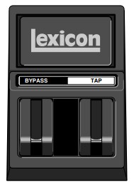 TYPICAL CONNECTIONS TO A CONSOLE
 SETTING AUDIO LEVELS
Note:
As with all audio products, it is good practice to first power on all outboard equipment, then the mixer, then the speakers.
INPUT
- Load Program 1.
- Set the Mix parameter to Dry (Edit Page 1, EDIT knob 4).
- Using high-level program material, begin with a low input level and advance it slowly.
- When audible distortion is reached or when the display clip indicators light and remain lit, lower the input level until the clip meters appear only on the highest peaks.
The Input Trim knob allows the unit to be driven by an input level within a range of +8 to +20dBu. The minimum setting (fully counterclockwise) should be optimal for +4dBu (balanced) inputs. The maximum setting (fully clockwise) should be optimal for -10dBV (unbalanced) inputs.
OUTPUT
- Press the front panel System button to activate System Mode. Output Level, the first System Mode parameter, will be displayed.
- Turn EDIT knob 3 to set the Output Level parameter. Unity gain for a +4dBu input device should be -12dB.
- Press the System button again to deactivate System Mode.
Basic Operation
SELECTING AND LOADING PROGRAMS
When powered on, the unit will load the last program that was loaded during the previous operating session.
To select another program, turn the front panel PROGRAM knob.
When the PROGRAM knob is turned clockwise, the unit will cycle forward through programs in the selected bank, then proceed to cycle forward through programs in the next bank. When turned counterclockwise, the unit will cycle backward through programs in the selected bank, then proceed to cycle backward through programs in the previous bank. When the PROGRAM knob is pushed inward and turned, the unit will cycle through program banks.
The name and number of the selected program appear n the front panel display (see page 1-6). The Load LED will light to indicate that the selected program is cued for loading. After 4 seconds, the front panel display will revert to showing the name and number of the loaded program. However, the Load LED will remain lit to indicate that the selected program is still cued for loading. The number of the cued program will appear in inverse video below the number of the currently loaded program. To load the cued program, press the front panel Load button.
The unit can be configured to automatically load programs 3/4 second after the PROGRAM knob stops turning. To do this, set the System Mode parameter Auto Load to Enabled (see page 3-7). EDITING PROGRAMS
Each program features up to 20 parameters, which are organized into Edit Pages with as many as four parameters each. Press the front panel Edit Pages button to cycle through available Edit Pages for the loaded program. Parameters available on the selected Edit Page appear across the bottom of the front panel display, as shown on page 1-6. The number below each parameter corresponds with the number above the Edit knob used to change its setting. When a parameter setting is changed, it will appear in inverse video on the front panel display and the Edit Pages LED will light to show that the program has been modified. The LED will no longer be lit when another program is loaded or if the modified version is stored.
If another program is selected before the modified program is stored, the edited version will still appear as the loaded program. However, the Load LED will light to indicate that a new program is cued  for loading.
THE “ADJUST” PARAMETER
An “Adjust” parameter has been customized for individual programs, and in most cases controls several parameters at once to handle complicated editing processes. For instance, “Adjust” controls the liveness of space in Chamber and Room programs by changing Decay, Early Reflections, and EQ simultaneously.
The “Adjust” parameter is located on Edit Page 1 and controlled with EDIT knob 1. It appears in parenthesis, such as (MidRT) pictured at the right. When EDIT knob 1 is turned, the bottom line of the front panel display shows a more complete description of the
parameter function in that program. The “Adjust” parameter is MIDI-compatible with a range of 0 to 127. 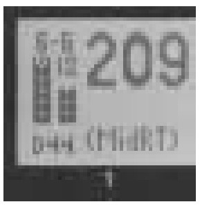 STORING PROGRAMS
The User Bank contains no programs when the MPX 550 is shipped. However, it includes 64 memory locations available for storing user-modified programs.
To store a program:
- Press the Store button. The Store and Tap/Cancel LEDs will light to indicate that the store function is armed. The first empty User Bank location will be selected.
 To cancel the store function without saving the program, press the Tap/Cancel button. This can be done at any time before the store procedure is completed.
- Use the PROGRAM knob to select a different User Bank location. The message area on the front panel display (see page 1-6) indicates whether the selected User Bank location is available or empty.
- The program appears on the front panel with its original name and a numeric suffix. If desired, use EDIT knobs 1 and 3 to change the name of the program.
- Press the Store button to save the program to the selected location. The message “Stored” will appear briefly on the display. The Edit LED will no longer be lit when the saved version becomes the selected program.
Note:
When storing a user program, allow the unit to complete the entire store process before powering the unit off. If the unit is power cycled during the process, all previously stored programs may be lost.
THE COMPRESSOR
The compressor is available in all programs, except Dynamics. (Dynamics uses a different compression mechanism, explained on page 4-33.) The compressor sits in the wet component of the signal in front of the effects in the loaded program. It is controlled with four parameters: CmpRatio, Threshld, CmpAttk, and CmpRels. These parameters are located on the last Edit Page for each program, except those in the Cmprssr The ratio (CmpRatio) parameter can be set to ratios of 1:1 (off), 2:1, 3:1, 4:1, 5:1, and 10:1. The threshold (Threshld) parameter can be set within a 0 to -32dB range. These settings are relative to 0dBFS (digital saturation). The compressor is disabled if either the ratio parameter is set to 1:1 or the threshold parameter is set high enough to prevent the incoming signal from crossing the compression threshold. The attack (CmpAttk) and release (CmpRels) parameters determine how fast the compressor responds, within 3dB of the output level dictated by the incoming signal.
For most music material, the release time should be about four times longer than the attack time. Both must be long enough to accommodate the bass content of the music.
If the compressor is set to react faster than the waveform of the music itself, the resulting changes in output level will re-shape the waveform enough to produce undesirable audio effects. For example, 80Hz has a period of 12ms. If this is a dominant component in the music, set both the attack and release parameters to at least 12ms, even higher for better results. The compressor acts on both the left and right channels at the same time, using the sum of the two channels as its trigger.
Compression presets are available in the Cmprssr Bank (see page 4-31). For other compression-only effects, send compressor output into a Dly/Eko program with the Delay parameter set to 0. The compressor does not add propagation delay to the audio path. (Note the converters introduce about 2ms of propagation delay.)
TAP TEMPO
MATCHING RHYTHM
Tap Tempo can be used to match the delay times and modulation rates of tempo-based programs with those of the music. The Tap/Cancel button LED will flash whenever a tempo-based program is loaded. The current tempo rate appears in the top-right corner of the front panel display.
It is not required to enter what “could be” the delay time in milliseconds. Just press the Tap/Cancel button twice, and the unit will calculate the appropriate delay time. To change tempo, press the Tap/Cancel button twice again in the new rhythm.![]() Tempo can also be set with a footswitch (see page 1-10) or MIDI control device (see page 6-4).
Tempo can also be set with a footswitch (see page 1-10) or MIDI control device (see page 6-4).
AUDIO TAP
To use audio input to set tempo:
- Press and hold the Tap/Cancel button until the message “Detecting audio…” appears at the top of the front panel display. (The optional dual footswitch allows the musician to continue playing the instrument while pressing and holding the Tap button.)
Tempo parameters available for the loaded program will also appear on the front panel display. - Still holding the Tap/Cancel button, play two short notes in rhythm.
- Release the Tap/Cancel button. The message “Knob to change” will appear at the top of the front panel display to indicate that EDIT knob 3 is now available to adjust tempo.
- If desired, turn EDIT knob 3 to further adjust tempo in bpm (beats per minute).
- Press the Tap/Cancel button to exit this mode.
Audio tap is a must for live performances. It offers a simple method of setting delay times and modulation rates to match the music.
GLOBAL TEMPO
The Tap/Cancel button LED will flash when a tempocontrolled program is loaded. Most factory presets are stored with individual tempo rates, which can be customized to suit personal taste. Tap in the new tempo, then store the modified version of the program in the
User Bank.
To recall the tempo rate stored with each program, set the System Mode parameter Tempo Mode (see page 3-5) to Program. The unit will apply the individual tempo setting of each program as it is loaded. To apply the current tempo rate to all programs, set the System Mode parameter Tempo Mode to Global. The unit will ignore individual tempo settings and apply the current tempo setting to each program as it is loaded.
BYPASS
The Bypass button can be used to force the unit to pass only dry audio, to mute the outputs immediately, or to mute the inputs to the loaded program. Its function depends on the setting of the System Mode parameter Bypass Mode (see page 3-5).
When Bypass Mode is set to Dry, the unit sends only dry, unprocessed audio to the outputs. When set to Full Mute, the unit mutes the outputs. When set to Input Mute, the unit mutes the inputs only. Running effects will continue their natural decay.![]() Bypass functions can also be activated with a footswitch (see page 1-10) or MIDI control device (see page 6-4).
Bypass functions can also be activated with a footswitch (see page 1-10) or MIDI control device (see page 6-4).
System Mode
SYSTEM MODE FUNCTIONS
System Mode can be used to set System Mode parameters, execute MIDI Dumps, and restore default settings. To enter System Mode, press the front panel System button. The System LED will light to indicate that System Mode is active.![]() The tables that begin at the right show System Mode functions. EDIT knob 1 selects the desired function, and EDIT knob 3 changes the parameter setting (if applicable). Changes to System Mode parameters are effective immediately. MIDI Dumps and Restore Default
The tables that begin at the right show System Mode functions. EDIT knob 1 selects the desired function, and EDIT knob 3 changes the parameter setting (if applicable). Changes to System Mode parameters are effective immediately. MIDI Dumps and Restore Default
Commands require confirmation to execute.
To exit System Mode, press the System button again.
Detailed descriptions of all System Mode functions begin on page 3-4.
| Parameter | Settings |
| Output Level | 0dB* to -31dB Off |
| Input Source | Analog Stereo* Analog Mono L, Analog Mono R S/PDIF Digital |
| Clock Source | Internal 44.1kHz* Internal 48kHz External (S/PDIF) |
| Digital Output | Processed* Dry |
| Mix Mode | Program* Global |
| Bypass Mode | Dry* Full Mute Input Mute |
| Program Load Mode | Bypass Dry* Full Mute |
| Tempo Mode | Program* Global |
| Compressor Mode | Program* Global |
| Parameter | Settings |
| MIDI Patches | Enabled* Disabled |
| MIDI Channel | Off 1* to 16 Omni |
| MIDI Program Change | Enabled* Disabled R1-MPX1 |
| MIDI Clock In | Enabled* Disabled |
| MIDI Out/Thru | Out* Thru |
| Operating Mode | Normal* Demo Locked |
| Memory Protect | Enabled Disabled* |
| Auto Load | Enabled Disabled* |
| Display Brightness | – |
| MIDI Dumps | Settings (if applicable) |
| Dump User Bank | 1-16 17-32 33-48 49-64 |
| Dump Current Program | – |
| Dump System Data | – |
| Restore Default Commands | |
| Clear User Bank | |
| Factory Init |
PARAMETERS
Output Level (0 to -31dB, Off)
Sets output level attenuation within a 0 to -31dB range, or off.
Input Source
(Analog Stereo; Analog Mono L and R; S/PDIF Digital) Selects input type. The current selection is indicated in the lower-left corner of the front panel display. “S” stands for Analog Stereo, “L” stands for Analog Mono L, “R” stands for Analog Mono R, and “D” stands for S/PDIF digital. The number following the prefix indicates the sample rate (48 or 44.1kHz). “NoD” indicates that no valid digital audio signal is present.
When set to Analog Stereo, the unit processes signals rom both analog inputs. When set to Analog Mono L, the unit sends signals from the ANALOG INPUT labelled LEFT to both processor inputs. When set to Analog Mono R, the unit sends signals from the ANALOG INPUT labelled RIGHT to both processor inputs.
When set to S/PDIF Digital, the unit processes signals from the S/PDIF IN connector. If no valid digital audio signal is present, the unit will mute and an alert message will appear on the front panel display.
Note:
When the Input Source parameter is set to S/PDIF Digital, the Clock Source parameter will automatically be set to External (S/PDIF).
Clock Source
(Internal 44.1kHz and 48kHz, External (S/PDIF)) Selects the internal or external clock source for the unit.
When set to Internal 44.1kHz, the unit utilizes an internal clock with a 44.1kHz sample rate. When set to Internal 48kHz, the unit utilizes an internal clock with a 48kHz sample rate. When set to External (S/PDIF), the unit utilizes the S/PDIF input signal, even if an analog source is used. “NoD” will appear in the lower-left corner of the front panel display if no valid digital input signal is present to utilize for the external clock.
Digital Output (Processed, Dry)
Selects the source for the digital output. When set to rocessed, the digital output is the same as the analog outputs. Its mix level will reflect the current setting of the Mix parameter. When set to Dry, the digital output is the input. This setting is useful for recording dry tracks while still providing processing at the analog outputs.
Mix Mode (Program, Global)
Controls the mix level that is applied when a new program is loaded. Mix levels are stored with each program. When Mix Mode is set to Program, the unit applies the stored mix level of the selected program to that program as it is loaded. When set to Global, the unit ignores stored mix levels and applies the current mix level to each program as it is loaded.
Bypass Mode (Dry, Full Mute, Input Mute)
Sets the function of Bypass. When set to Dry, the unit sends only dry, unprocessed audio to the outputs. When set to Full Mute, the unit mutes the outputs. When set to Input Mute, the unit mutes the inputs only. Running effects will continue their natural decay.
Program Load Mode (Bypass Dry, Full Mute)
Controls the processing of incoming audio signals during program load. When set to Bypass Dry, the unit sends only dry, unprocessed audio to the outputs. When set to Full Mute, the unit mutes during program load.
Tempo Mode (Program, Global)
Controls the tempo setting that is applied when a new program is loaded. A tempo setting is stored with each program. When Tempo Mode is set to Program, the unit5 applies the stored tempo setting of each program as it is loaded. When set to Global, the unit applies the current tempo setting to each program as it is loaded.
Compressor Mode (Program, Global)
Controls the compression settings that are applied when a new program is loaded. Compression settings are stored with each program. When Compressor Mode is set to Program, the unit applies the stored setting of each program as it is loaded. When set to Global, the unit applies the current compression setting to each program as it is loaded.
MIDI Patches (Enabled, Disabled)
Enables and disables Learned Patches. When set to Enabled, the unit responds to Learned Patches. When set to Disabled, the unit ignores Learned Patches, preventing accidental changes.
MIDI Channel (Off, 1 to 16, Omni)
Selects the MIDI Channel for MPX 550 messages. When set to Off, the unit ignores messages sent on all MIDI channels. When set within a range of 1 to 16, the unit responds to messages sent on the selected MIDI channel. When set to Omni, the unit responds to messages sent on all MIDI channels.
MIDI Program Change (Enabled, Disabled, R1-MPX 1) Enables and disables MIDI Program Change messages. When set to Enabled, the unit responds to MIDI Program Change messages. When set to Disabled, the unit ignores MIDI Program Change messages, preventing accidental changes. When set to R1-MPX 1, the unit responds to program change messages from a Lexicon MPX R1 Foot Controller set to MPX 1 Mode.
MIDI Clock In (Enabled, Disabled)
Enables and disables MIDI Clock messages. When set to Enabled, Tap Tempo is changed by incoming MIDI messages. When set to Disabled, the unit ignores MIDI Clock messages, preventing accidental changes.
MIDI Out/Thru (Out, Thru)
Controls the function of the MIDI OUT/THRU connector.
When set to Out, the unit can generate its own MIDI Dumps. When set to Thru, the unit can forward – but cannot generate or modify – MIDI messages.
Operating Mode (Normal, Demo, Locked)
Controls front panel knobs and buttons. When set to Normal, front panel controls perform their normal functions. When set to Demo, front panel controls are placed in a continuous program load cycle for demonstration purposes. When set to Locked, front panel controls are locked to their current settings. When front panel controls are locked:
- The front panel PROGRAM knob is still available for selecting user programs only. Programs stored in the User Bank are still available, but cannot be modified.
- The System Mode parameter Auto Load is set to Enabled.
- Bypass functions are still available.
- Tempo and Patches cannot be learned.
- System Mode can still be activated.
Changes to the Operating Mode parameter will not take effect until the unit has been powered off, then powered on again.
Memory Protect (Enabled, Disabled)
Protects the User Bank from accidental changes. When set to Enabled, the unit prevents changes to the User Bank. However, it does not prevent changes to System Mode parameters, nor does it prevent the restoration of factory-default settings. Restoring default settings will till erase all programs stored in the User Bank. When set to Disabled, the unit does not prevent changes to the User Bank.
Auto Load (Enabled, Disabled)
Determines whether the front panel Load button must be pressed to load selected programs. When set to Enabled, programs will automatically load 3/4 second after the PROGRAM knob stops turning. When set to Disabled, programs will not load until the Load button is pressed.
Display Brightness
Controls the brightness of the front panel display. Turn EDIT knob 3 clockwise to make the display darker, and counterclockwise to make the display brighter.
MIDI DUMPS
Dump User Bank (1-16, 17-32, 33-48, 49-64)
Executes a MIDI Dump of User Bank programs to an external MIDI device, such as a sequencer. These programs can be dumped back to the unit. This is useful to preserve User Bank programs from deletion prior to restoring default settings. User programs are dumped in groups of 16, depending on the group selected by EDIT knob 3. Once a group is selected, press the front panel Store button to execute the Dump. When dumped back, the group will be returned to its original User Bank location.
Dump Current Program
Executes a MIDI Dump of the currently active program.
This allows programs to be saved to an external MIDI device. Press the front panel Store button to execute the dump. When dumped back, the program will automatically become the currently active program.
Dump System Data
Executes a MIDI Dump of all System Mode settings and Learned Patches. Press the front panel Store button to execute the dump. When dumped back, the System Mode settings and Learned Patches will take effect immediately.
RESTORE DEFAULT COMMANDS
Clear User Bank
Arms a procedure to erase the contents of the User Bank.
Press the front panel Store button to execute this procedure and return the User Bank to its factory-default condition. This procedure cannot be executed when a User program is running or when the System Mode
parameter Memory Protect is set to Enabled.
Factory Init
Arms a procedure to restore parameters, System Mode parameters, User Bank programs, and Learned Patches to their factory-default conditions. Press the front panel Store button to execute this procedure.
Program Descriptions
SINGLE PROGRAMS
PLATE
Plate reverb began with a large, thin sheet of metal suspended upright under tension on springs.
Transducers attached to the plate transmitted a signal that made the plate vibrate, causing sounds broadcast through it to appear to be occurring in a large, open space.
The Plate programs synthesize the sound of metal plates with high initial diffusion and a relatively bright, colored sound. These programs are designed to be heard as part of the music, mellowing and thickening the sound. Plate programs are a popular choice for enhancing pop music, particularly percussion.
| Plate | Programs | Adjust | Tap |
| 1 | Small Plate | (Livenes) | – |
| 2 | Medium Plate | (Livenes) | – |
| 3 | Large Plate | (Livenes) | – |
| 4 | Tap PreDelay | (MidRT) | PreDelay (1/32 Note) |
| 5 | Tape Slap | (ips) | – |
| 6 | Rich Plate | (MidRT) | – |
| 7 | Large&Bright | (MidRT) | – |
| 8 | VocalPlate | (Livenes) | Echo |
| 9 | Drum Plate | (Livenes) | – |
GATE/INV
Gated reverbs were created by feeding a reverb, such as a metal plate, through an analog gate device. Decay time was set to instant, while hold time varied duration nd sound.
The Gate programs provide a fairly constant sound with no decay until the reverb is cut off abruptly. These programs work well on percussion, particularly on snare and toms. It is recommended to experiment with other sound sources as well.
Note:
Adjusting the Time or Duration parameters will cause the selected program to reload. The System Mode parameter Program Load Mode determines whether the system will mute or bypass during program load.
| Gate | Inv Programs | Adjust | Tap |
| 10 | StraightGate | (Time) | – |
| 11 | Slope Down | (Time) | – |
| 12 | Drum Gate | (HighCut) | PreDelay (1/32 Note) |
| 13 | 140ms,TapPre | (HighCut) | PreDelay (1/32 Note) |
| 14 | 240ms,TapPre | (HighCut) | PreDelay (1/32 Note) |
| 15 | 340ms,TapPre | (HighCut) | PreDelay (1/32 Note) |
| 16 | 440ms,TapPre | (HighCut) | PreDelay (1/32 Note) |
| 17 | 540ms,TapPre | (HighCut) | PreDelay (1/32 Note) |
| 18 | Inverse | (Time) | – |
| 19 | Dark Inverse | (Time) | – |
HALL
Lexicon’s Hall programs recreate the acoustics of actual places – from grand, reverberant enclosures to small concert halls.
The clean reverberation of Hall programs is designed to add spaciousness without altering source material. In addition to general instrumental and vocal applications, the Hall programs give separately recorded tracks a sense of belonging to the same performance.
| Hall | Programs | Adjust | Tap |
| 20 | Small Hall | (MidRT) | – |
| 21 | Medium Hall | (MidRT) | – |
| 22 | Large Hall | (MidRT) | – |
| 23 | Small Church | (MidRT) | – |
| 24 | Large Church | (MidRT) | – |
| 25 | Jazz Hall | (MidRT) | – |
| 26 | Dance Hall | (MidRT) | – |
| 27 | Synth Hall | (MidRT) | – |
| 28 | Concert Hall | (MidRT) | – |
| 29 | Gothic Hall | (MidRT) | – |
CHAMBER
Historically, recording studio chambers were oddly shaped rooms with a loudspeaker and set of microphones to collect ambience in various parts of the room.
Stereo Chamber programs produce even, relatively dimensionless reverberation with little color change as sound decays. The initial diffusion is similar to Hall programs. However, the sense of size and space is much less obvious. This characteristic, coupled with the low color of the decay tail, makes these programs useful on a wide range of material – especially the spoken voice. Chamber programs give the spoken voice a noticeable increase in loudness with low color.
| Chamber | Programs | Adjust | Tap |
| 30 | Brick Wall | (HighCut) | – |
| 31 | Basement | (HighCut) | – |
| 32 | LiveConcert | (Livenes) | Eko Delay |
| 33 | Drum Chamber | (MidRT) | – |
| 34 | Moves on . . . | (Livenes) | – |
| 35 | Live Chamber | (Livenes) | – |
| 36 | VocalChambr1 | (Livenes) | Eko Delay |
| 37 | VocalChambr2 | (Livenes) | Eko Delay |
| 38 | WideChamber | (Livenes) | |
| 39 | PCM60: Large | (MidRT) |
AMBIENCE
Ambience adds warmth, spaciousness, and depth to a performance without coloring its direct sound. It is commonly used to add a room sound to recorded music and speech. In music recording, Ambience can realistically add distance to close-mic’ed signals.
Ambience programs simulate reflections from room surfaces with random reflections, a gradual decay of overall level, and a gradual narrowing of bandwidth. In these programs, the Mix control adds depth – emulating the movement of a coincident pair of microphones away from the sound source into the room.
| Ambience | Programs | Adjust | Tap |
| 40 | Announcer | (HighCut) | – |
| 41 | VerySmallAmb | (HighCut) | – |
| 42 | Small Amb | (HighCut) | – |
| 43 | MidSizeAmb | (HighCut) | – |
| 44 | Studio “D” | (HighCut) | – |
| 45 | Bright Amb | (Decay) | – |
| 46 | Dark Amb | (Decay) | – |
| 47 | MarbleFoyer | (Livenes) | – |
| 48 | Smooth Amb | (Decay) | – |
| 49 | Guitar Amb | (HighCut) | – |
ROOM
Room programs simulate actual rooms where there is a strong sense of being in a small, live place. These programs are useful on drums and percussion, and can also be applied to electric guitar tracks.
| Room | Programs | Adjust | Tap |
| 50 | Bedroom | (Walls) | – |
| 51 | Tiled Room | (LFBoost) | – |
| 52 | Studio “C” | (MidRT) | – |
| 53 | Small Room | (Livenes) | – |
| 54 | Studio “B” | (MidRT) | – |
| 55 | Rehearsal Rm | (EQ) | – |
| 56 | Studio “A” | (MidRT) | – |
| 57 | Large Room | (EQ) | – |
| 58 | Fat Space | (MidRT) | – |
| 59 | Chunky Space | (EQ) | – |
TREMOLO
Tremolo is a rhythmic change in loudness, commonly employed as an expressive technique by vocalists and wind instrument players. It is also one of the oldest effects, frequently used with electric guitar, electric piano, and occasionally vocals. Different tremolo effects are largely determined by the rate (fast or slow) and waveform shape (smooth or sharp) of the change in loudness. If the effect is used in a stereo mix, the left and right can be synchronized to produce dramatic side-toside motion.
The Tremolo programs offer classic tremolo shapes, such as square, sawtooth, triangle, sine, and rectified sine. The synchronization of the left and right channels can be adjusted to produce mono and stereo effects. The Tap button sets tremolo rates, making it simple to match the tempo of the music. The “Adjust” parameter (Phase) sets left and right channel waveforms out-of-phase, resulting in a panning motion.
Set the Mix parameter to Wet for all programs. Mix can be used to effectively set the depth of the Tremolo program when more dry is added to the wet-to-dry mix.
It is recommended to make the rate work with the tempo of the music, as Tremolo is essentially a rhythmic effect.
| Tremolo | Programs | Adjust | Tap |
| 60 | (Phase) | Rate (1/8 Note) | |
| 61 | (Phase) | Rate (1/8 Note) | |
| 62 | (Phase) | Rate (1/4 Note) | |
| 63 | (Phase) | – | |
| 64 | (Phase) | – |
ROTARY
Rotary speaker cabinets were designed to provide a majestic vibrato/choir effect for electronic theater and church organs. The most well-known rotary speaker is the Leslie™ Model 122, which has two counter-rotating elements: a high-frequency horn and a low-frequency drum with slow and fast speeds. The sound generated as the spinning elements change speed is truly magical. The swirling, spacious effect is difficult to describe – but immediately recognizable.
The Rotary programs are a detailed simulation of a Lesliestyle cabinet. The input signal is split into high and low-frequency bands. The rotation effect is created by a synchronized combination of pitch shifting, tremolo, and panning. Like the physical cabinet, the high (horn) and low (drum) frequencies are “spun” in opposite directions. Horn and drum speeds are independent, and designed with acceleration and deceleration characteristics to simulate the inertia of the original mechanical elements.
A virtual requirement for organ music, Rotary programs also sound remarkable with guitar and electric piano rhythm parts. In fact, these programs are great alternatives to chorus and tremolo effects for any sound source.
To achieve the full effect, set the Mix parameter to Wet for all programs.
| Rotary | Programs | Adjust | Tap |
| 65 | Rot:SlowFast | (Switch) | – |
| 66 | Rot Slow | (Resnce) | – |
| 67 | Rot SpeedAdj | (Speed) | – |
| 68 | Rot TapRate1 | (Balance) | Rate |
| 69 | Rot TapRate2 | (Resnce) | Rate |
CHORUS
Chorus effects create lush, full sounds by multiplying the riginal audio source. Traditionally, these effects were used to fatten up tracks and to add body to guitar without coloring the original tone. Chorus effects are also often combined with plates, echoes, and other reverb effects.
The stereo Chorus programs, inherited from Lexicon’s PCM 80, create a rich, airy effect that simulates the sound of multiple sources from a single source. These programs are stunning on acoustic or clean electric guitar.
These programs utilize six independently randomized delay voices panned across the stereo field. Set the Mix parameter to Wet to achieve the full richness of the 6-voice chorus.
| Chorus | Programs | Adjust | Tap |
| 70 | Chorus1 | (Resnce) | – |
| 71 | Chorus2 | (HighCut) | – |
| 72 | Chorus3 | (Diffusn) | – |
| 73 | Slap Chorus1 | (Diffusn) | – |
| 74 | Slap Chorus2 | (Depth) | – |
FLANGE
Flange effects were originally created by simultaneously playing back identical programs on two tape recorders, then using hand pressure against the flange of the tape reels to slow down first one machine, then the other. The result was a series of changing phase cancellations and reinforcements, with characteristic swishing, tunneling, and fading sounds.
The stereo flanger has two 2-Tap delays – one per channel. The first tap is fixed, and the second sweeps past it. Mixing the two delay taps together creates the flanging effect.
Set the Mix parameter to Wet to achieve the full flange effect of these programs.
| Flange | Programs | Adjust | Tap |
| 75 | Flng Lite | (Rate) | – |
| 76 | Flng Lite180 | (Resnce) | – |
| 77 | Flng Med180 | (Rate) | – |
| 78 | Flng Deep | (Resnce) | – |
| 79 | Flng Deep180 | (Resnce) | – |
DETUNE
Detune effects create delayed and pitch-shifted versions of the original source, thickening the sound. This creates a particularly effective simulation of double-tracking.
These effects are also great alternatives to Chorus effects, adding the richness of a chorus without the audible sweep caused by the chorus rate.
The 4-voice stereo Detune programs have one pair of voices per channel. As more detune is applied with the dry signal. “Adjust” parameter, the pair become more out of tune, providing a lush sound without the need for mixing in a
Set the Mix parameter to Wet to achieve the full effect of these programs.
| Detune | Programs | Adjust | Tap |
| 80 | Detune Mild | (Dtuning) | – |
| 81 | Detune Med&Warm | (Dtuning) | – |
| 82 | Detune Heavy | (Dtuning) | – |
| 83 | Det Xtreme | (Dtuning) | – |
| 84 | Pitch Detune | (Dtuning) | – |
PITCH
Altering the pitch of a sound produces a wide range of effects – from subtle detuning, to harmonies, to chords.
The stereo polyphonic Pitch programs can be used to shift program material or monophonic sources within a range of one octave up to two octaves down.
For pitch correction, set the Mix parameter to Wet. For harmonization, set the Mix parameter to the desired setting.
| Pitch | Programs | Adjust | Tap |
| 85 | Pch Chrmatic | (Pitch) | – |
| 86 | Pitch Fine | (Pitch) | – |
| 87 | Pch 4th-5ths | (Pitch) | – |
| 88 | Pch PowerInv | (Inversn) | – |
| 89 | Vocal Chorus | (HighCut) | – |
DLY/EKO
Delays and echoes repeat a sound a short time after it first occurs. The simplest (and oldest) delay effect is tape slap – a single repeat about 100ms after the original sound. Tape slap was often used on Elvis Presley’s voice and rockabilly guitar tracks.
Tape slap becomes tape echo when the output of the tape is fed back into the input (feedback). This turns a single repeat into a series of repeats, each a little softer and a little darker than the last. This darkening is characteristic of the analog tape recording process.
Digital echoes do not have this characteristic; each repeat has the same exact timbre. For digital echoes, loudness is the only difference from repeat to repeat. Tape and digital echoes are both useful, but different.
Tape echo is warmer, allowing the original sound to distinguish itself. Digital echo presents a “perfect” copy of the original sound.
The DLY/EKO programs include mono (5.5 seconds), stereo (2.7 seconds), and 6-voice multi-tap effects. Each program can be used for tape or digital delay or echo effects. When the “Adjust” parameter (Edit Page 1, EDIT knob 1) is set to a value between 0 and 63, digital delay effects are produced. Each repeat is the same timbre, but softer. When the “Adjust” parameter is set to a value between 64 and 127, tape effects are produced. Each repeat is darker and softer.
In programs 90 to 97, the “Adjust” parameter sets the amount of feedback with an increasing number 0of repeats as the setting is increased. Delay time is set with Tap. Each program is preset with a different useful rhythm. In programs 98 to 104, the amount of feedback is preset and the “Adjust” parameter determines the delay time.![]() With all delay and echo effects, note the way the repeats fall rhythmically to the beat. The most effective delay and echo patterns are those that lock with the tempo of the music.
With all delay and echo effects, note the way the repeats fall rhythmically to the beat. The most effective delay and echo patterns are those that lock with the tempo of the music.
In all delay programs and dual programs, the unit uses the MstrDly parameter to scale delay times that are not controlled by Tempo. In some programs, the “Adjust” parameter controls MstrDly.
MstrDly can be set within a range of 0 to 100%. It is usually set to 100% in most presets. When MstrDly is set manually (or by the “Adjust” parameter) to less than 100%, individual delay times will scale accordingly. For example, if MstrDly is set to 25%, all delay times will be reduced to 1/4 of their normal value. Knobs that control those delay times will become correspondingly less sensitive – requiring, in this example, four times as many clicks to obtain the normal result.
| Dly | Eko Programs | Adjust | Tap |
| 90 | Dly Mono Tap | (FeedBk) | Delay Time |
| 91 | DlyStereoTap | (FeedBk) | Delay Time |
| 92 | Dly ShuflTap | (FeedBk) | Delay Time |
| 93 | Dly Dot8 Tap | (FeedBk) | Delay Time |
| 94 | Dly 8+3plTap | (FeedBk) | Delay Time |
| 95 | Dly Pong Tap | (FeedBk) | Delay Time |
| 96 | Dly XFbkTap1 | (FeedBk) | Delay Time |
| 97 | Dly XFbkTap2 | (FeedBk) | Delay Time |
| 98 | Dly Mono | (Time) | – |
| 99 | Dly Stereo | (Time) | – |
| 100 | Dly TapeSlap | (Time) | – |
| 101 | Multi Bounce | (Time) | – |
| 102 | MultiInverse | (Time) | – |
| 103 | Multi Linear | (Time) | – |
| 104 | Multi Pong | (Time) | – |
| Special | FX Programs | Adjust | Tap |
| 105 | Infinite | (HighCut) | Eko |
| 106 | The Abyss | (Dtuning) | – |
| 107 | Jet Flange | (Resnce) | Speed (Whole Note) |
| 108 | Verb>Chorus | (HighCut) | – |
| 109 | TapRot Dly | (Time) | Rate (Drum/Horn) |
| 110 | Fader Verb | (Level) | Echo |
| 111 | Low Rumble | (Decay) | – |
| 112 | Ducker Verb | (Decay) | – |
| 113 | DuckerChorus | (Resnce) | – |
| 114 | Stereo Stage | (Width) | – |
| 115 | Echoes:Beats | (Delay) | Delay Time |
| 116 | Panning Dlys | (FeedBk) | Dly Time, Pan Rate |
| 117 | DreamSequenc | (Pitch) | – |
| 118 | Infinite Dly | (FeedBk) | Delay Time (Whole Note) |
| 119 | Diffusor | (Diffusn) | – |
STEREO STAGE
Stereo Stage provides stereo reverb while preserving the dry signal. To use this program, note the following:
- Use the MPX 550 in line between the mixer and house amplifiers – not as an effect mixed back into the main left and right channels on the mixer.
- Pan the input channels on the mixer fully to each musician’s side of the stage.
- Keep the Mix parameter set to 50% (the default Program Load Mode setting).
- Adjust reverb level by setting the Efx Bal parameter between 100:0% (full left) and 60:40%.
- The ideal setting for the Width parameter depends on the distance between the speakers at each side of the stage. The program loads with an assumed spacing of about 20 feet, with an adjustment range of 10 to 50 feet. The width setting assumes that most audience members are seated within about 30 degrees to either side of the stage centerline. If audience members are seated further to the sides of the stage, the setting can be increased. Otherwise, it should be kept as low as possible.
DUAL PROGRAMS
The dual programs combine Delay with Reverb, or either Delay or Reverb with Flange, Pitch, or Chorus. Four routing configurations are used in the variations of each dual program: Dual Stereo (Parallel), Cascade, Mono Split, and Dual Mono.
- Flng-Dly, Pch-Dly, Chor-Dly, Dly-Rvb, Flng-Rvb, Pch-Rvb, and Chor-Rvb
The first six programs in these banks feature two effects arranged in Dual Stereo (Parallel) configuration. Both effects receive signals from the left and right inputs, and both effects send signals to the left and right outputs. The last four programs in these banks feature two effects arranged in Cascade configuration. The first effect passes its signal to the second effect. For example, in Flng-Dly, Flange passes its signal to Delay. - MSplit Dly, MSplit Rvb
These banks contain programs that are arranged in Mono Split configuration, which is similar to the 5Dual Stereo (Parallel) configuration. One effect (e.g. Flange) receives signals from the left input and the other effect (e.g. Delay) receives signals from the right input. However, both effects send signals to the left and right outputs. - Dual Mono
This bank contains programs that are arranged in the Dual Mono configuration. One effect (e.g. Flange) receives input from the left channel only and sends utput to the left channel only. The other effect (e.g. Delay) receives input from the right channel nly
and sends output to the right channel only.

EFX BAL
The Efx Bal parameter controls the relative balance of each effect in the dual programs. In Cascade variations, the parameter also varies the amount of the first effect or dry signal fed into the second effect.
The illustration below uses the Pch-Dly program to show the effect of the Efx Bal parameter at certain settings when a Cascade variation is selected. FLNG-DLY
| Flng-Dly | Programs | Adjust | Tap Delay | Routing |
| 120 | Flng Tap | (FeedBk) | Time (1/4 Note) | Dual Stereo (Parallel) |
| 121 | Flng .8Tap | (FeedBk) | Dotted (1/8 Note) | Dual Stereo (Parallel) |
| 122 | Flng 3plTap | (FeedBk) | Triplet (1/8 Note) | Dual Stereo (Parallel) |
| 123 | Flng PongTap | (FeedBk) | Delay Time (1/4 Note) | Dual Stereo (Parallel) |
| 124 | Flng Xfeed | (Time) | – | Dual Stereo (Parallel) |
| 125 | Flng Bounce | (Time) | – | Dual Stereo (Parallel) |
| 126 | Flng > Tap | (FeedBk) | Delay Time (1/4 Note) | Cascade |
| 127 | Flng > Fbk | (Time) | – | Cascade |
| 128 | Flng > Pong | (FeedBk) | Delay Time (1/4 Note) | Cascade |
| 129 | Flng > Bnce | (Time) | – | Cascade |
 PCH-DLY
| Pch-Dly | Programs | Adjust | Tap | Routing |
| 130 | 5th Tap | (Pitch) | Delay Time | Dual Stereo (Parallel) |
| 131 | 8ve 3pl Tap | (Pitch) | Delay Time | Dual Stereo (Parallel) |
| 132 | 8ve 8+3plTap | (Pitch) | Delay Time | Dual Stereo (Parallel) |
| 133 | 3rd4thPong | (Pitch) | Delay Time | Dual Stereo (Parallel) |
| 134 | 4th5th Xfeed | (Pitch) | Delay Time | Dual Stereo (Parallel) |
| 135 | 5th6th Xfeed | (Pitch) | Delay Time | Dual Stereo (Parallel) |
| 136 | 8ve > Xfeed | (Pitch) | Delay Time | Cascade |
| 137 | 5th > Xfeed | (Pitch) | Delay Time | Cascade |
| 138 | MajMin > Fbk | (Pitch) | Delay Time | Cascade |
| 139 | StepUp > Tap | (Pitch) | Delay Time | Cascade |
 CHOR-DLY
| Chor-Dly | Programs | Adjust | Tap | Routing |
| 140 | Chor Tap | (FeedBk) | Delay Time | Dual Stereo (Parallel) |
| 141 | Chor .8Tap | (FeedBk) | Delay Time | Dual Stereo (Parallel) |
| 142 | Chor 8+3pl | (FeedBk) | Delay Time | Dual Stereo (Parallel) |
| 143 | Chor Pong | (FeedBk) | Delay Time | Dual Stereo (Parallel) |
| 144 | Chor Repeat | (Time) | – | Dual Stereo (Parallel) |
| 145 | Chor Bounce | (Time) | – | Dual Stereo (Parallel) |
| 146 | Chor > Tap | (FeedBk) | Delay Time | Cascade |
| 147 | Chor >Repeat | (Time) | – | Cascade |
| 148 | Chor > Pong | (FeedBk) | Delay Time | Cascade |
| 149 | Chor > Bnce | (Time) | – | Cascade |
 DLY-RVB
| Dly-Rvb | Programs | Adjust | Tap | Routing |
| 150 | Tap Small | (MidRT) | Delay Time | Dual Stereo (Parallel) |
| 151 | 3plTap MidSz | (MidRT) | Delay Time | Dual Stereo (Parallel) |
| 152 | 8+3pl Large | (MidRT) | Delay Time | Dual Stereo (Parallel) |
| 153 | Pong Small | (Decay) | Delay Time | Dual Stereo (Parallel) |
| 154 | Xfeed MidSz | (Decay) | Delay Time | Dual Stereo (Parallel) |
| 155 | Xfeed Large | (Decay) | Delay Time | Dual Stereo (Parallel) |
| 156 | Tap > Room | (Livenes) | Delay Time | Cascade |
| 157 | 8+3pl >Large | (MidRT) | Delay Time | Cascade |
| 158 | Xfeed > Room | (Livenes) | Delay Time | Cascade |
| 159 | Xfeed >Large | (MidRT) | Delay Time | Cascade |
 FLNG-RVB
| Flng-Rvb | Programs | Adjust | Tap | Routing |
| 160 | LiteFl Small | (MidRT) | Speed (Whole Note) | Dual Stereo (Parallel) |
| 161 | LiteFl MidSz | (MidRT) | Speed (Whole Note) | Dual Stereo (Parallel) |
| 162 | LiteFl Large | (MidRT) | – | Dual Stereo (Parallel) |
| 163 | DeepFl Small | (MidRT) | – | Dual Stereo (Parallel) |
| 164 | DeepFl MidSz | (MidRT) | – | Dual Stereo (Parallel) |
| 165 | DeepFl Large | (MidRT) | – | Dual Stereo (Parallel) |
| 166 | LiteFl>Small | (MidRT) | Speed (Whole Note) | Cascade |
| 167 | LiteFl >Room | (Livenes) | Speed (Whole Note) | Cascade |
| 168 | DeepFl>Large | (MidRT) | – | Cascade |
| 169 | DeepFl >Room | (Livenes) | – | Cascade |
 PCH-RVB
| Pch-Rvb | Programs | Adjust | Tap | Routing |
| 170 | 3rd4th Room | (Pitch) | – | Dual Stereo (Parallel) |
| 171 | 4th5th Room | (Pitch) | – | Dual Stereo (Parallel) |
| 172 | 5th6th Room | (Pitch) | – | Dual Stereo (Parallel) |
| 173 | 8ve MidSiz | (Pitch) | – | Dual Stereo (Parallel) |
| 174 | Power MidSiz | (MidRT) | – | Dual Stereo (Parallel) |
| 175 | Detune Room | (Dtuning) | – | Dual Stereo (Parallel) |
| 176 | Fine > Small | (Pitch) | – | Cascade |
| 177 | Power >Large | (MidRT) | – | Cascade |
| 178 | 4th > MidSiz | (MidRT) | – | Cascade |
| 179 | 8ve > MidSz | (MidRT) | – | Cascade |
 CHOR-RVB
| Chor-Rvb | Programs | Adjust | Tap | Routing |
| 180 | Chor1 Small | (MidRT) | – | Dual Stereo (Parallel) |
| 181 | Chor1 MidSiz | (MidRT) | – | Dual Stereo (Parallel) |
| 182 | Chor1 Large | (MidRT) | – | Dual Stereo (Parallel) |
| 183 | Chor2 Small | (MidRT) | – | Dual Stereo (Parallel) |
| 184 | Chor2 MidSiz | (MidRT) | – | Dual Stereo (Parallel) |
| 185 | Chor2 Large | (MidRT) | – | Dual Stereo (Parallel) |
| 186 | Chor1 > Room | (Livenes) | – | Cascade |
| 187 | Chor2 > Room | (Livenes) | – | Cascade |
| 188 | Chor3 > Room | (Livenes) | – | Cascade |
| 189 | Chor1 >Small | (MidRT) | – | Cascade |
 MSPLIT DLY
| MSplit Dly | Programs | Adjust | Tap | Routing |
| 190 | Flng + Tap | (FeedBk) | 1/4 Note | Mono Split |
| 191 | Flng + Pong | (FeedBk) | 1/4 Note | Mono Split |
| 192 | Flng + Xfeed | (Time) | – | Mono Split |
| 193 | Flng + Bnce | (Time) | – | Mono Split |
| 194 | DeepFl + Dly | (Time) | – | Mono Split |
| 195 | 5th + Tap | (Pitch) | Delay Time | Mono Split |
| 196 | 8ve + 3plTap | (Pitch) | Delay Time | Mono Split |
| 197 | 4th5th+Xfeed | (Pitch) | Delay Time | Mono Split |
| 198 | 5th6th+Xfeed | (Pitch) | Delay Time | Mono Split |
| 199 | PchFine +Tap | (Pitch) | Delay Time | Mono Split |
| 200 | Chor + Tap | (FeedBk) | Delay Time | Mono Split |
| 201 | Chor + Pong | (FeedBk) | Delay Time | Mono Split |
| 202 | Chor + Xfeed | (Time) | – | Mono Split |
| 203 | Chor + Bnce | (Time) | – | Mono Split |
| 204 | Chor+Inverse | (Time) | – | Mono Split |
Note: The Mono Split routing configuration is illustrated on page 4-18.
MSPLIT RVB
| MSplit Rvb | Programs | Adjust | Tap | Routing |
| 205 | Tap + MidSiz | (MidRT) | Delay Time | Mono Split |
| 206 | Pong + Large | (MidRT) | Delay Time | Mono Split |
| 207 | Bnce + MidSz | (MidRT) | Delay Time | Mono Split |
| 208 | Xfeed + Small | (MidRT) | Delay Time | Mono Split |
| 209 | Xfeed+MidSiz | (MidRT) | Delay Time | Mono Split |
| 210 | LiteFl+MidSz | (MidRT) | – | Mono Split |
| 211 | LiteFl+Large | (MidRT) | – | Mono Split |
| 212 | DeepFl+Small | (MidRT) | – | Mono Split |
| 213 | DeepFl+MidSz | (MidRT) | – | Mono Split |
| 214 | DeepFl +Room | (Livenes) | – | Mono Split |
| 215 | 4th5th +Room | (Pitch) | – | Mono Split |
| 216 | 5th6th +Room | (Pitch) | – | Mono Split |
| 217 | 4ths + Large | (MidRT) | – | Mono Split |
| 218 | 8ve + MidSz | (MidRT) | – | Mono Split |
| 219 | PchFin+MidSz | (Pitch) | – | Mono Split |
| 220 | Chor1 +Small | (MidRT) | – | Mono Split |
| MSplit Rvb | Programs | Adjust | Tap | Routing |
| 221 | Chor1+ Large | (MidRT) | – | Mono Split |
| 222 | Chor2+MidSiz | (MidRT) | – | Mono Split |
| 223 | Chor2+ Large | (MidRT) | – | Mono Split |
| 224 | Chor3+MidSiz | (MidRT) | – | Mono Split |
Note: The Mono Split routing configuration is illustrated on page 4-18.
DUAL MONO
| 225 | Tap | Small | (MidRT) | Delay Time | Dual Mono |
| 226 | Tap | MidSiz | (MidRT) | Delay Time | Dual Mono |
| 227 | Tap | Large | (MidRT) | Delay Time | Dual Mono |
| 228 | Tap | Room | (Livenes) | Delay Time | Dual Mono |
| 229 | DeepFl | Tap | (FeedBk) | Speed (1/4 Note) | Dual Mono |
| 230 | DeepFl | Dot8 | (FeedBk) | Speed (Dotted 1/4 Note) | Dual Mono |
| 231 | 8ves | Tap | (Pitch) | Delay Time | Dual Mono |
| 232 | 8ves | 3pl | (Pitch) | Delay Time | Dual Mono |
| 233 | Chor2 | Tap | (FeedBk) | Delay Time | Dual Mono |
| 234 | Chor2 | Dot8 | (FeedBk) | Delay Time | Dual Mono |
| 235 | LiteFl | Large | (MidRT) | Speed | Dual Mono |
| 236 | DeepFl | Large | (MidRT) | – | Dual Mono |
| 237 | 8ves | MidSz | (MidRT) | – | Dual Mono |
| 238 | 4ths | Large | (MidRT) | – | Dual Mono |
| 239 | Chor1 | Room | (Livenes) | – | Dual Mono |
CMPRSSR
In all Cmprssr programs, the “Adjust” parameter controls gain within a range of 0 to 9.5dB. It can be used to match volume levels between the dry, bypassed, and compressed output obtained with typical music material.
If the System Mode parameter Mix Mode is set to Program, the Mix parameter will automatically be set to Wet, allowing the compressed delay signal to be the only output signal present. If the System Mode parameter Mix Mode is set to Global, the Mix parameter must be set manually.
The five compressor-reverb presets offer a reverb component in parallel with a zero-delay dry component.
The compressor acts on both. The Mix parameter should be set to Wet, and the effective mix should be adjusted with the Efx Bal parameter.
| Comprssr | Programs | Adjust | Tap |
| 240 | Two to One | (Gain) | – |
| 241 | Three to One | (Gain) | – |
| 242 | 3:1 Small | (Gain) | PreDelay |
| 243 | 5:1 Medium | (Gain) | PreDelay |
| 244 | 3:1 Large | (Gain) | PreDelay |
| 245 | GuitarComp | (Gain) | – |
| 246 | Limiter | (Gain) | – |
| 247 | Male Vocal | (Gain) | PreDelay |
| 248 | Female Vocal | (Gain) | PreDelay |
* Presets 240, 241, 245, and 246 are compressor only. Presets 242, 243, 244, 247, and 248 are combination compressor and reverb with Dual Stereo (Parallel) routing.
DYNAMICS
Note:
A few seconds after the Dynamics preset is loaded, the Dynamics name will flash briefly on the front panel display. This does not affect audio input or output.
Dynamics is intended for use in the studio, when dynamic processing of stereo signals is required. Because of its long delay, this preset is not recommended for use in a live performance or as a mix insert. It includes effects that perform peak expansion, compression, and tape saturation in that order.
Dynamics includes nine parameters that are divided into three Edit Pages. Peak expansion settings are controlled on the first page, compression settings are controlled on the second page, and tape saturation settings are controlled on the third page. The first page also features a switch that selects between gain reduction and input metering.
PEAK EXPANSION
Peak expansion is used to raise the overall level of sound sources that rise above the adjustable peak expansion threshold. In performances with a wide dynamic range, peak expansion can increase the level of low-level sound sources. For example, for a relatively quiet instrument that swells in volume without the desired impact, peak expansion can raise the instrument level during the swell.
ExpThrsh (-31 to 0dB)
Controls the threshold above which expansion is applied. Lower settings enable low-level sound sources to expand. Higher settings enable only very high-level peaks to expand.
ExpLvl (0.0dB to 5.89dB)
Controls the amount of expansion that is applied to sound sources that rise above the expansion threshold.
The parameter setting defines the maximum increase in signal level due to expansion. Higher settings increase the level of expansion applied. Maximum expansion is applied to signals that rise well above the expansion threshold for longer than 50ms.
Meters (GR, In)
Selects between gain reduction (GR) and input level (In) metering. (See page 4-35 for more information.)
COMPRESSION
Compression is used to lower the overall level of sound sources that rise above an adjustable compression threshold. Compression can be used to match the levels of louder sources to those of quieter sources.
Ratio (1:1 to 10:1)
Determines the level of gain reduction applied when the sound source rises above the compression threshold. It can be set in ratios of 1:1, 1.60:1, 2.00:1, 2.66:1, 3.20:1, 4.00:1, 5.33:1, 8.00:1 and 10:1. For each dB rise in input to the compressor, the ratio indicates the fraction of the dB rise in output. For example, when Ratio is set to 4.00:1, the output will rise 0.25dB for each dB rise in input to the compressor. Higher settings will result in more compression.
Thresh (-31 to -0dB)
Designates the compression threshold, the level the sound source must rise above before compression is applied.
Attack (200 to 3.0msec)
Determines how fast the compressor responds to sound sources that rise above the compression threshold. Slower settings allow the signal to rise above the threshold for short periods of time with minimal compression.
Release (4.0 to .30sec)
Determines how fast compression is reduced when sound sources fall below the compression threshold. Slower settings reduce compression gradually. Faster settings reduce compression more quickly, causing the level of the sound source to be tracked more closely.
TAPE SATURATION
Tape saturation emulates the sound of sources recorded on analog tapes and sources recorded digitally. Because of the natural peak saturation that occurs with analog tapes, sound sources recorded on them seem louder than the same sound sources recorded digitally. To use this effect, increase the Gain parameter setting. The amount of gain used is guided by both the output level meter and, more importantly, the ear. Gain levels that are too high can dramatically reduce the dynamic range of sound sources, possibly causing objectionable distortion – just like real tape. Gain (Min, 1 to 30, Max)
Determines average output level. Lower settings prevent signal saturation. Higher settings reduce peaks within the sound source relative to the average level of the sound source, enabling the peak saturation block to reduce peak levels. The setting can be increased to its maximum level without causing digital overload. However, excessive peak saturation may distort the signal.
Saturation (Off, Modern, Vintage)
Controls the amount of saturation.
LEVEL METERS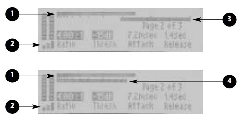
- Output Level Meter
Indicates output levels. The value indicates the maximum output level of the left or right channel, whichever is greater. The tick marks are placed in 3dB increments. The right most tick mark indicates 0dB or maximum output level. - Peak Expansion Meter
Indicates the level of peaks above the peak expansion threshold. Low-level peaks are shown as one or two graduated bars. Slightly higher peaks of longer duration are shown as three graduated bars. High-level peaks are shown as three solid bars.
Note: Use the Meters parameter to select between gain reduction and input level metering. - Gain Reduction Meter
When the Meters parameter is set to GR, indicates the output level reduction due to compression. The value shown indicates the maximum left or right channel gain reduction, whichever is greater. The meter moves from right to left. The tick marks are placed in 3dB increments. The right-most tick mark represents 0dB or no gain reduction. Each tick mark proceeding from right to left indicates an additional 3dB of gain reduction. - Input Meter
When the Meters parameter is set to In, indicates the maximum left or right channel input levels, whichever is greater. The associated tick marks are placed in 3dB increments. The right-most tick mark indicates 0dB or maximum input level.
TYPICAL MASTERING DYNAMICS CONTROL
ADJUSTMENT
The following is a common scenario for musical sources that have not previously been compressed:
- For analog input sources, adjust the front panel Input Trim knob so the input meters peak in the -6dB range. The input meters should never exceed the 0dB level.
- Beginning at 0dB, reduce the setting of the ExpThrsh parameter until peaks in the source material cause the peak expansion level meter to show 1 to 3 graduated bars. High-level peaks in the sound source –3dB. will cause the peak expansion meter to show three solid bars for short periods of time. Increase the ExpLvl parameter until the peaks in the source material sound slightly exaggerated. Then, reduce the setting until the peaks sound natural.
- Set the Ratio parameter to 4.00:1, the Attack parameter to 7.2msec, and the Release parameter to 1.4sec. Beginning at 0dB, reduce the setting of the Thresh parameter until the gain reduction meter moves between 0 and 3 to 6dB of gain reduction. If the output level sounds unnatural, increase the settings of the Attack and Release parameters. If output levels are too low after peaks occur, increase the setting of the Release parameter. If output levels are still too low after peaks occur, increase the setting of the ExpLvl parameter.
- Beginning at 0, adjust the Gain parameter setting until the output level meter shows peaks above
LIVE-FOH (FRONT OF HOUSE)
Live-FOH programs are designed for live performances, with controls that are more convenient for live-sound engineers to operate. These programs use Dual Mono routings to accommodate the sound reinforcement systems (PAs) used in most small-to-mid-sized venues.
Often, these systems provide limited channels and mono aux sends for effects.
For Live-FOH presets:
- Edit Page 1 contains the four most essential parameters for the first effect, and Edit Page 2 contains the four most essential parameters for the cond effect. Non-essential parameters have been removed from the Edit Pages.
- In the delay programs, two delay level controls have been combined into the “Adjust” parameter: (Tap/ Dly). These programs contain two delays. The first is controlled by tempo and generally used to create longer delays and echoes. The second is set manually with the Delay parameter, and can be used to create a “slap” of 60 to 135ms.
The (Tap/Dly) parameter provides an inverse level control for these delays. The default setting provides equal levels of each. The tempo-controlled delay is suited for longer rhythm-sensitive effects, while the manually-controlled delay is suited for shorter times. However, both delays are capable of delivering a full range of delay times that can be crossfed into each other for more extreme effects. - The Dly/Reverb program is available with alternative EDIT knob assignments (255). The first two Edit Pages are arranged with delay parameters on the left and reverb parameters on the right. This arrangement splits effect controls left-to-right rather than page-to-page.
| Live-FOH | Programs | Adjust | Tap |
| 250 | Flange/Dly | (Tap/Dly) | Delay Time |
| 251 | Chorus/Dly | (Tap/Dly) | Delay Time |
| 252 | Flange/Rvb | (Tap/Dly) | – |
| 253 | Chorus/Rvb | (Tap/Dly) | – |
| 254 | Dly/Reverb | (Tap/Dly) | Delay Time |
| 255 | Dly/Reverb | (Tap/Dly) | Delay Time |
Parameter Descriptions
PARAMETER GRAPHICS
The MPX 550 features graphic enhancements for each parameter, which appear on the front panel display whenever a parameter setting is changed. These graphics illustrate the point at which the selected setting falls within the entire parameter range, and provide a visual indication of the parameter’s function. As the setting changes, the graphic also changes to reflect the new setting. Examples are shown below and on the following page. To view other parameter graphics, change the setting of the desired parameter.

PARAMETER GLOSSARY
Note:
System Mode parameters are described in Section 3.
Dynamics parameters are described on pages 4-32 to 4-35. These parameters are not included in this glossary.
“Adjust” (0 to 127)
Functions differently from preset to preset. “Adjust” is a “magic” control that can manipulate several parameters at once or provide a set of special values for a single control. For example, it may be called (Fast) or (Slow) for a parameter that is also settable to any value via another control. “Adjust” has a range of 0 to 127 to provide a convenient attachment point for a MIDI controller.
Attack (0 to 100 or 0 to 255)
Controls the sharpness of the initial response to an input signal. High settings cause explosive sounds, while low settings cause sounds to build up more slowly with time. Attack only affects the level of sound within the first 50ms or so.
Balance (-100 to +100%)
In Rotary programs, determines the volume balance between the horn and drum.
BassMult (0.2 to 4.0x)
Controls the reverb time for low-frequency signals.
BassMult works as a multiplier of the Decay and MidRT parameters. For example, if BassMult is set to 2.0x, and Decay is set to 2 seconds, the low-frequency reverb time will be 4 seconds. For a natural-sounding hall ambience, BassMult should be set between 1.0x and 2.0x.
BassXvr (28Hz to 19.4kHz, off)
Sets the frequency below which BassMult applies.
CmpAttk (4 to 125msec)
Controls the speed at which the compressor responds when input signals increase above threshold. threshold.
CmpRatio (1:1 (off) to 10:1)
Sets the ratio of gain reduction for input signals above
CmpRels (4 to 250msec)
Controls the rate at which the compressor relaxes when compressed input signal levels fall.
Decay (73ms to 19.61sec or 24ms to 6.53sec)
Controls reverb time for mid frequency signals. In Ambience programs, Decay controls the length of the ambience “tail”.
Depth (0 to 100%)
Controls the level of volume modulation.
Diffusion (0 to 100%)
Controls the degree to which initial echo density increases over time. High settings result in a high initial buildup of echo density. (Echo density is also affected by Size, with smaller spaces sounding denser.)
Dly Fbk (0 to 100%)
Serves as a master control determining the feedback of left into left and right into right.
Dly HiCut (28Hz to 19.4kHz, off)
Appears in Dual programs where one effect is Dly/Eko, providing independent control over the Dly/Eko high-frequency output. Dly HiCut applies a high-cut filter similar to HF Rlloff to the Delay/Echo effect.
Dly Lvl (off, -24dB to 0dB)
Controls the overall level of the signal fed into the Delay, Echo effect.
Dly Lvl 1, 2, 3 (off, -48dB to 0dB)
Controls the levels of voice set 1, 2, or 3 for both the left and right channels.
Dly XFbk (0 to 100%)
Determines the feedback of left into right and right into left.
DlyTapLvl (off, -48 to 0dB)
Appears in dual programs where one effect is Delay/Echo and one or more delay voice is controlled by Tap. DlyTapLvl controls the level of the Tap-controlled voice that is mixed into the Delay/Echo effect.
Drum Dep (0 to 100%)
In Rotary programs, determines the amount of modulation produced by the drum.
Drum Res (-100 to +100%)
In Rotary programs, determines the amount of resonance, i.e. signal, fed back into the effect.
Duration (140 to 700ms)
In Gate/Inv programs, determines the length of time that passes before the output is cut off.
Efx Bal (100:0% to 0:100%)
Controls the relative amounts of the two effects in Dual programs. In a Dual Stereo (Parallel), Mono Split, or Dual Mono configuration, this splits the signal to be fed into the two effects. In a Cascade configuration, it also allows some of the signal to bypass either of the two effects.
EkoDly L, R (0ms to 1.198sec)
Control the timing of single reflections that occur early in the decay in the reverb programs. These reflections simulate the sound sometimes heard off the back wall of a stage or other reflective surface.
EkoFbk L, R (-100 to 100%)
Control the amount of repeating echo that simulates a flutter echo between parallel walls in the reverb programs. The range of these parameters is from -100% to 100%, with negative values producing a polarity reversal. High settings can cause signal overload.
HF Rlloff (28Hz to 19.4kHz, off)
Sets the high-frequency cutoff of a low-pass filter.
HighSlope and LowSlope (-16 to +15)
Determine the shape of the reverb envelope for low frequencies. HighSlope and LowSlope are found only in the Gate/Inv programs. When LowSlope is set to 0, the level of low reverb remains unchanged over its duration, then cuts off abruptly. Setting LowSlope above 0 causes the level of low-frequency reverb to rise smoothly from soft to loud until the sound is cut off. The greater the slope, the softer the initial reverberation and the more pronounced its rise. When set to a negative value, the low-frequency reverb drops to a quieter level before cutoff. HighSlope is similar to LowSlope, but applies to middle and high frequencies.
Horn Dep (0 to 100%)
In Rotary programs, determines the amount of modulation produced by the horn.
Horn Res (-100 to +100%)
In Rotary programs, determines the amount of resonance, i.e. signal fed back into the effect.
Intrvl (Varies)
Controls the amount of pitch-shift applied. Intrvl values are in semi-tones. Pch values are in Cents (1/100th of a semi-tone). These values are additive.
L Dly 1, 2, 3 (0ms to 5.060sec)
Sets the delay time of left voice 1, 2, or 3. The Dly/Eko effect has three independent voices on each side.
Level (0 to 100%)
Determines the amount of wet signal present in the output. It functions similar to Mix, except it affects the wet component only. Level is generally used to balance the overall output of two or more programs when Mix is set to wet.
LowSlope and HighSlope (-16 to +15)
See HighSlope and LowSlope.
Mix (Dry, 1 to 99%, Wet)
Mix controls the ratio of unprocessed (Dry) and processed (Wet) signal in the output. When the MPX 550 is patched into a console, this parameter should almost always be set to Wet.
MstrRate (0 to 100%)
In Rotary programs, serves as a master rate control affecting both the horn and drum rates.
Pch Fbk (L), (R) (-100% to +100%)
Controls the amount of feedback through the Pitch pre- sets, resulting in repeated echoes with pitch progressing up or down.
Pch (L), (R/S) (-2400 to 2600)
Control the amount of pitch-shift applied to the left and right channels. For true stereo programs, the Pch(L) parameter is not available and the Pch(R/S) parameter eans stereo. For mono programs, the Pch(L) and (R/S) parameters mean left and right respectively.
Pitch-shifting requires some time shifting. A true stereo (not merely Dual Mono) signal contains components that are common to the left and right signals. A proper stereo image is maintained only if the phase relationship between the left and right signals is maintained. This requires that the exact same computation be applied to oth channels, which is why only one control is provided for Pitch presets.
PDly (L), (R) (0 to 100ms)
Controls the amount of “look-ahead” required by the pitch-shift algorithm. Some amount of pre-delay is always in effect, even when this parameter is set to 0.
Phase (0 to 270deg)
Determines the relative timing between the left and right channels. PreDelay (0ms to 1.198sec)
Controls the time delay between the input of signal and the onset of reverberation.
R Dly 1, 2, 3 (0ms to 5.060sec)
Sets the delay time of right voice 1, 2, or 3. The Dly/Eko effect has three independent voices on each side.
Rate (0 to 50.05Hz)
Controls modulation speeds.
Res 1, 2 (-100 to +100%)
In Chorus programs, control the amount of feedback signal.
Resonanc (-100 to +100%)
In Flange programs, controls the amount of feedback.
Rt HC (28Hz to 19.4kHz, off)
Sets the frequency above which high frequencies are rolled off in the reverberated signal, causing reverberated signals to grow progressively darker. This results in a more natural sound because it simulates the effect of air absorption in a real hall. Setting this parameter to a low- frequency dampens the audio as it re-circulates, and consequently can actually shorten the reverb time.
RvbLvl (off, -48dB to 0dB)
In Ambience programs, controls the amount of “extra” longer-decay reverb added to the effect. In Ambience, short-decay early reflections create a real-room sound.
Shape (0 to 255)
Controls the buildup of the early reflections that most audibly create the sound of a real room. Shape and Spread work together; if either is set to 0, the other has no effect.
Size (4.0 to 76.0m)
Sets the rate of echo density buildup after the initial period (which is controlled by Diffusion). It also acts as a master control for Decay. Size changes a reverb sound from very small to very large. It is recommended to set the Size control to the approximate size of the acoustic space that is being created before adjusting other parameters. The size in meters is roughly equal to the longest dimension of the space. (Adjusting the Size parameter causes the program to re-load.)
Speed (0 to 5000)
In Flange programs, controls how rapidly the two “flange” voices move.
Speed 1, 2 (0 to 5000)
In Chorus programs, control the rates at which the various voices sweep through frequency.
Spread (0 to 255)
Controls the timing between the initial reflections that most audibly create the sound of a real room. Shape and Spread work together; if either is set to 0, the other has no effect.
Sweep (0 to 100ms)
In Flange programs, determines the maximum amount of time-delay applied to each voice.
Sweep 1, 2 (0 to 100ms)
In Chorus programs, control the amount of frequency variation for two different collections of voices. (The Chorus effect simulates six voices with slightly varying pitch. Separate controls are available over two sets of three voices each.)
Threshld (-32 to -0dB)
Controls the level above which signals are compressed.
Tune 1, 2 (0 to 100%)
In Detune programs, determines the amount of detuning applied to voices 1 and 2.
Wavform (See Below)
In Tremolo programs, determines volume modulation. Settings are defined as follows:
| Setting | Description |
| Sine | Smooth modulation with polarity reversal. |
| Rectified Sine | Smooth modulation with no polarity reversal. |
| Triangle | Linear ramp up and down. |
| Sawtooth | Linear ramp up with sudden reduction. |
| Square | Level modulates between maximum and minimum. |
Width (0 to 100%)
Determines the effective separation between the left and right channels.
MIDI Operation
LEARN MODE
Learn Mode enables the MPX 550 to “learn” MIDI Program Change and Continuous Controller messages.
To activate and deactivate Learn Mode, press the Store and Tap/Cancel buttons simultaneously. The Store and Tap/Cancel LEDs will light to indicate that Learn Mode is active. The front panel display will then show the current patching for EDIT knobs 1 to 4 (Edit Page 1). To access knobs 5 to 20, press the Edit Pages to cycle to the desired Edit Page.
The unit supports learned patches for Bypass and Tap, as well as all available parameters controlled with the front panel Edit knobs.
MIDI CHANNEL ASSIGNMENT
A single, selectable MIDI channel is used for all MPX 550 messages. This channel can be assigned in System Mode with the MIDI Channel parameter.
Note:
A MIDI channel should be assigned before MIDI features are used. PROGRAM CHANGE MESSAGES
LOADING PROGRAMS
Standard MIDI Program Change messages can be used o load all 255 presets and 64 user programs. The unit conforms to the use of MIDI Continuous Controller 32 to execute Bank Select messages. MPX 550 program banks are ordered numerically from 0 to 27, beginning with the Plate Bank. (See the table at the right for additional bank numbers.)
Any program can be loaded by selecting its bank with Controller 32, then sending the appropriate Program Change message.
For example, if the Plate Bank is selected:
- Sending Program Change 1 will load the first Plate program (Small Plate).
- Sending Controller 32 with a value of 27 followed by Program Change 1 will load the first program in the User Bank.
MIDI Program Banks
| 0 | Plate |
| 1 | Gate/Inv |
| 2 | Hall |
| 3 | Chamber |
| 4 | Ambience |
| 5 | Room |
| 6 | Tremolo |
| 7 | Rotary |
| 8 | Chorus |
| 9 | Flange |
| 10 | Detune |
| 11 | Pitch |
| 12 | Dly/Eko |
| 13 | Special FX |
| 14 | Flng-Dly |
| 15 | Pch-Dly |
| 16 | Chor-Dly |
| 17 | Dly-Rvb |
| 18 | Flng-Rvb |
| 19 | Pch-Rvb |
| 20 | Chor-Rvb |
| 21 | MSplit Dly |
| 22 | MSplit Rvb |
| 23 | Dual Mono |
| 24 | Cmprssr |
| 25 | Dynamics |
| 26 | Live-FOH |
| 27 | User |
• Sending Controller 32 with a value of 1 followed by Program Change 2 will load the second program (Slope Down) in the Gate/Inv Bank.
Once a bank is selected, all subsequent Program Change messages will select programs within that bank until a ew value for Controller 32 is received, or until another program or bank is selected with the front panel PROGRAM knob.
MIDI Program Change messages can be disabled in System Mode with the MIDI Program Change parameter.
ACTIVATING BYPASS OR TAP FUNCTIONS
The unit can recognize MIDI Program Change messages 100 to 127 (101 to 128 on some MIDI devices) for activating Bypass or Tap functions.
To assign a Program Change message to the Bypass or
Tap controls:
- Simultaneously press the Store and Tap buttons to activate Learn mode.
- Press the desired front panel button – Bypass or Tap. The front panel display will indicate the current patch on the selected control.
- Send the MIDI Program Change message to the MPX 550. The front panel display will indicate the new patch on the control, and “Stored” will appear briefly in the message area.
- Press the Store button to commit the assignment.
- Simultaneously press the Store and Tap buttons to deactivate Learn Mode.
Some MIDI controllers do not allow repeated Program hange messages to be sent with a single button. To assist these controllers, the unit also recognizes the next highest Program Change message with each Program
Change message it learns for Bypass and Tap. For instance, if Program Change 20 is learned as the source for Bypass, Program Change 21 will also control Bypass functions. To avoid conflicting Bypass and Tap assignments, leave a space between the assignments of these two buttons.
CONTINUOUS CONTROLLERS
The unit recognizes Pitch Bend, AfterTouch, and MIDI Continuous Controllers 1 to 31 and 33 to 119.
To learn a Continuous Controller:
- Simultaneously press the Store and Tap buttons to activate Learn mode.
- Turn the desired EDIT knob or press the desired button on the front panel. The front panel display will indicate which control is selected, as well as the current controller range.
- Select the desired controller using one of the following methods:
A. Move the MIDI controller through its full range. To use a portion of the controller range, limit this movement to the desired range. The message area on the front panel display will indicate incoming MIDI activity.
B. Rotate the EDIT knob until the desired Controller number is displayed. The full range of the
Controller (0 to 127) will be assumed. This method is not available for Bypass and Tap. - Press the Store button to commit to the assignment. The word “Stored” will appear briefly in the message area of the front panel display.
- To assign another front panel control, repeat steps 2 to 4.
- Simultaneously press the Store and Tap buttons to deactivate Learn Mode.
Note:
When a MIDI controller is assigned to the Bypass control, moving the controller above the mid-point of its learned range engages Bypass. Moving the controller below the mid-point range disengages Bypass. When a MIDI controller has been assigned to the Tap control, moving the controller above the mid-point of its learned range will “tap” the control as if the Tap button had been pressed.
MIDI CLOCK
The unit recognizes MIDI Clock messages and applies the tempo (40 to 400bpm) to programs that use Tap Tempo. Connect a MIDI device that outputs MIDI Clock, such as the MPX R1 foot controller or a MIDI sequencer, to the MPX 550 MIDI IN connector to have the MPX 550 automatically recognize and begin to process MIDI Clock messages. When the tempo of the connected device changes, the unit will automatically adjust its delay times and modulation rates to match the new tempo.
Note:
This feature can be disabled with the System Mode parameter MIDI Clock In.
When System Mode is active, the unit will not respond to MIDI Clock messages. Once System Mode is deactivated, the unit will resume responding to MIDI Clock messages.
MIDI DUMPS
MIDI Dumps can be used to save the user programs, the selected program, or the System Mode settings and Learned Patch assignments to a storage device (typically a MIDI sequencer). MIDI Dumps are performed in System Mode (see page 3-8).
To perform a dump of the user programs, the selected program, or the System Mode settings and Learned Patches:
- Press the front panel System button. The System LED will light to indicate that System Mode is active.
- Use the EDIT knob 1 to select:
• Dump User Bank
Executes a dump of user programs. Use Edit knob 3 to select the desired range of user programs: (1-16), (17-32), (33-48), or (49 to 64). When a user program dump is returned to the unit from a MIDI storage device, the unit saves it in the appropriate User Bank locations.
• Dump Current Program
Executes a dump of the selected program.
• Dump System Data
Executes a dump of System Mode settings and Learned Patch assignments. - Press Store to execute the dump.
- Press System to deactivate System Mode.
Note:
MIDI Dumps will not be executed unless the System Mode parameter MIDI Out/Thru is set to Out (see page 3-6).
SYSEX MESSAGES
MIDI Sysex messages can be used to access all algorithm parameters. More information about using this advanced feature with the MPX 550 and other Lexicon products is available at www.lexicon.com. The website offers instructions, sample messages, and a complete table of parameter Sysex addresses.
Note:
Executing MIDI Sysex messages is a complicated process. Please observe the cautionary notes included on the website.
MIDI IMPLEMENTATION CHART
| Function | Transmitted | Recognized | Remarks | |
| Basic | Default | X | 1 | Selected in System Mode |
| Channel | Channel | X | 1-16 | |
| Mode | Default Messages Altered | X | Mode 2 X X | |
| Note Number | True Voice | X | X | |
| Velocity | Note ON | X | X (Off=9n, v=0) | |
| Note OFF | X | X | ||
| After | Keys | X | X | Used as controller |
| Touch | Channels | X | OX | Selected in System Mode |
| Pitch Blender | X | OX | Used as controller Learned | |
| Control Change | X | OX | 1 to 119 (0 to 32 used as Bank Select) Learned |
| Function | Transmitted | Recognized | Remarks | ||
| Program Change | True # Bank Select | X X | 0 to 15 = 1 to 16 X | 16 to 127 ignored; Program Change messages 1 to 15 = Program Change messages 1 to 16 for selected program bank as applicable * | |
| System | Lexicon | O | O | Lexicon ID = 6; Product ID = 22 | |
| Exclusive | Real Time | X | X | (decimal); Device ID = MIDI Channel | |
| non-Real Time | X | X | 0 to15 = 1 to 16 | ||
| System | :Song Pos | X | X | ||
| :Song Sel | X | X | |||
| Common | :Tune | X | X | ||
| System | :Clock | X | O | ||
| Real Time | :Commands | X | X | ||
| Aux | :Local ON/OFF | X | X | ||
| Messages | :All Notes OFF :Active Sense :Reset | X X | X X | ||
| Mode 1: OMNI ON, POLY | Mode 2: OMNI ON, MONO | O: | Yes | ||
| Mode 3: OMNI OFF, POLY | Mode 4: OMNI OFF, MONO | X: | No | ||
| OX: | Selectable | ||||
* Program Change messages that do not correspond to a valid program in the current bank will be ignored.
Appendix
| Audio Inputs | XLR, T/R/S balanced |
| Connectors | +8 to +20dBu full-scale |
| Level Impedance | 50K balanced 25K unbalanced |
| A/D | 24-bits 20Hz to 20kHz±1dB |
| Dynamic Range | 105dB, typical |
| Crosstalk | -96dB@1kHz |
| Analog Audio Outputs | |
| Connectors | XLR, T/R/S balanced |
| Level | balanced +20dBu unbalanced |
| Impedance | <600Ω |
| D/A | 24-bits 20Hz to 20kHz±1dB |
| Dynamic Range | 101dB, typical |
| Crosstalk | -96dB@1kHz |
| Digital Audio Inputs and Outputs | |
| Connectors | Coaxial RCA S/PDIF (IEC-958, CP-340) |
| System Sample Rates | 44.1kHz, 48kHz (Internal Clock and S/PDIF Input) |
| Front Panel Display | 150×32 LCD, backlit |
| Footswitch | Tip/Ring/Sleeve phone jack for Bypass and Tap (optional) |
| MIDI Interface Connectors | IN, OUT/THRU |
| Power Requirements | 90 to 250V, 50 to 60Hz; 12.5W, 3-pin IECconnector |
| Dimensions (W x H x D) | |
| Width | 19 inches (483mm) |
| Height | 1.75 inches (45mm) |
| Depth | 4 inches (102mm) |
| Weight | 3 pounds (1.4kg) |
| Environment | |
| Operating Temperature | 32 to 104˚F (0 to 40˚C) |
| Relative Humidity | 95% non-condensing |
| RFI/ESD | FCC Class B European EMC Directive 89/336/ECC |
Specifications are subject to change without notice.
DECLARATION OF CONFORMITY
| Application of Council Directive(s): | 73/23/EEC, 89/336/EEC, and 93/68/EEC |
| Standard(s) to which Conformity is Declared: | EN 55103-1, EN 55103-2, and EN 60065: 1998 |
| Manufacturer: | Lexicon, Inc., 3 Oak Park, Bedford, MA 01730-1441 USA The equipment identified here conforms to the Directive(s) and Standard(s) specified above. |
| Type of Equipment: | Dual Channel Processor |
| Model: | Lexicon MPX 550 |
| Date: | Feb-02 |
| Dual Mono Programs | 4-18, 4-30 |
| Dual Programs | 4-18 to 4-30 |
| Dual Stereo (Parallel) Configuration | 418 |
| Dump Current Program | 3-8, 6-7 |
| Dump System Data | 3-8. 6-7 |
| Dump User Bank | 3-8, 6-6 |
| Duration Parameter | 5-6 |
| Dynamics | 4-32 to 4-36 |
| EDIT Knobs | .1-5, 1-7, 2-3 |
| Edit Pages Button | 1-4, 2-3 |
| Editing Programs | 3-Feb |
| Efx Bal Parameter | 4-19, 5-6 |
| EkoDly L, R Parameters | 5-6 |
| EkoFbk L, R Parameters | 5-6 |
| ExpLvl Parameter (Dynamics) | 4-32 |
| ExpThrsh Parameter (Dynamic: | 4-32 |
| Factory Init | 3-9 |
| Flange Programs | 4.11 |
| Fing-Dly Programs | 4-18, 4-20 |
| Fing-Rvb Programs | 4-18, 4-24 |
| Footswitch Connector | 1-8, 1-10 |
| Front Panel | 2 1-4 to 1-7 |
| Front Panel Display | 1-5, 1-6 to 1-7 |
| Gain Parameter (Dynamics) | 4-34 |
| Gain Reduction Meter (Dynamics) | 4-35 |
| Gate/Inv Programs | 4-9 |
| Global Tempo | 2-7 |
| Hall Programs | .4-4 |
| HF Rlloff Parameter | 5-2, 5-6 |
| HighSlope Parameter | 5-7 |
| Horn Dep Parameter Horn Res Parameter | 5-7 |
| Horn Res Parameter | 5-7 |
| Input Level Meters . | 1-6 |
| Input Levels, Setting | 1- 12 |
| Input Meter (Dynamics) | .4-35 |
| Input Source Parameter | 3-4 |
| Input Trim Knob | 1-4 |
| Input/OVL Indicator | 1-6 to 1-7 |
| Inputs, Rear Panel | 1-8 to 1-11 |
| Inspection Instructions | ix to xiv |
| Intrvl Parameter | 5-7 |
| L Dly 1, 2, 3 Parameters | 5-7 |
| Learn Mode | 6-2 |
| Level Meters (Dynamics) | 4-34 to 4-35 |
| Level Parameter | .5-3, 5-7 |
| Limited Warranty | Inside Back Cover |
| Live-FOH Programs | 4-36 to 4-37 |
| Load Button | 1-5, 2-2, 2-3 |
| Loading Programs | 2-2, 6-3 |
| LowSlope Parameter | 5-7 |
| Mastering Dynamics | 4-32 to 4-36 |
| Matching Rhythm | 2-6 |
| Memory Protect Parameter* | 3-7 |
| Messages, Front Panel Display | 1-7 |
| Meters Parameter (Dynamics) | 4-33 |
| MIDI Channel Assignment | 6-2 |
| MIDI Channel Parameter* | 3-6, 6-2 |
| MIDI Clock | .6-6 |
| MIDI Clock Parameter* | 3-6, 6-6 |
| MIDI Dumps | 3-3, 3-8, 6-6 to 6-7 |
| MIDI Implementation Chart | 6-8 to 6-9 |
| MIDI IN Connector | 1-8 |
| MIDI Learn Mode | 6-2 |
| MIDI OUT/THRU Connector | .1-8 |
| MIDI Out/Thru Parameter* | 3-6, 6-7 |
| MIDI Patches Parameter* | 3-6 |
| MIDI Program Banks | .6-3 |
| MIDI Program Change Parameter* | 3-6 |
| Mix Mode Parameter* | 3-5 |
| Mix Parameter | 5-3, 5-8 |
| Mono Split Configuration | 4-18 |
| MPX 550, About the | 1-2 to 1-3 |
| MSplit Dly Programs | 4-18, 4-27 |
| MSplit Rvb Programs . | 4-18, 4-28 to 4-29 |
| MstrRate Parameter | 5-8 |
| Operating Mode Parameter*7 | 3-6 to 3-7 |
| Output Level Meter (Dynamics) | .4-34 |
| Output Level Parameter* | .3-4 |
MPX 550
| utput Levels, Setting | 1-12 |
| Outputs, Rear Panel | 1-8 to 1-11 |
| OVL Indicator | 1-6 to 1-7 |
| Parallel (Dual Stereo) Configuration | 4-18 |
| Parameter Glossary | .5-4 to 5-11 |
| Parameter Graphics | 5-2 to 5-3 |
| Parameters, Dynamics | 4-32 to 4-34 |
| Parameters, System Mode | 3-2 to 3-7 |
| Pch (R), (L/S) Parameter | .5-8 |
| Pch Fbk (L), (R) Parameters | 5-8 |
| Pch-Dly Programs | 4-18, 4-19, 4-21 |
| Pch-Rvb Programs | .4-18, 4-25 |
| PDly (L), (R) Parameters . | 5-8 |
| Peak Expansion (Dynamics) | 4-32 to 4-33 |
| Peak Expansion Meter (Dynamics) | .4-35 |
| Phase Parameter | .5-8 |
| Pitch Programs | 4-13 |
| Pitch Shift | 4-19 |
| Plate Programs | 4-2 |
| Power Switch | 1-5 |
| PreDelay Parameter | 5-8 |
| Program Banks, MIDI | 6-3 |
| Program Change Messages | 6-2, 6-3 to 6-4 |
| Program Descriptions | 4-1 to 4-37 |
| PROGRAM Knob | 1-5, 2-2, 2-4 |
| Program Load Mode Parameter* | 3-5 |
| Program Name | 1-7 |
| Program Number | 1-7 |
| R Dly 1, 2, 3 Parameters | 5-9 |
| Rate Parameter | .5-9 |
| Ratio Parameter (Dynamics) | 4-33 |
| Rear Panel | 1-8 to 1-9 |
| Release Parameter (Dynamics) | 4-33 |
| Res 1, 2 Parameters | 5-9 |
| Resonanc Parameter | 5-9 |
| Restore Default Commands | 3-3, 3-9 |
| Room Programs | .4-7 |
| Rotary Programs | 4-9 |
| Routing Configuration | 1-7, 4-18 |
| Rt HC Parameter | .5-9 |
| RvbLvl Parameter | .5-9 |
| S/PDIF Connectors | 1-9 |
| Safety Instructions . | Inside Front Cover |
| Inside Front Coveriv to viii, ix to xiv | |
| Saturation Parameter (Dynamics) | 4-34 |
| Selecting Programs | 2-2 |
| Setting Audio Levels | 1-12 |
| Shape Parameter | 5-9 |
| Single Programs | 4-2 to 4-15 |
| Size Parameter | 5-9 |
| Special FX Programs | .4-16 to 4-17 |
| Specifications | A-2 |
| Speed Parameter | 5-10 |
| Speed 1, 2 Parameters | 5-10 |
| Spread Parameter | 5-10 |
| Stereo Stage Program | .4-17 |
| Store Button | -5, 2-4, 6-2 |
| Storing Programs | 2-4 |
| Sweep Parameter | .5-10 |
| Sweep 1, 2 Parameters | 5-10 |
| Sysex Messages | .6-7 |
| System Button | 1-4, 3-2 |
| System Mode | 3-2 to 3-9 |
| System Mode Parameters | 3-2 to 3-7 |
| Table of Contents | ii to iii |
| Tap/Cancel Button 6-2, 6-4, 6-5 | .1-5, 2-4, 2-6 to 2-7, |
| Tap Tempo | .1-7, 2-6 to 2-7 |
| Tape Saturation (Dynamics) | 4-34 |
| Tempo Mode Parameter* | 2-7, 3-5 |
| Thresh Parameter (Dynamics) | 4-33 |
| Threshld Parameter | 2-5, 5-10 |
| Tremolo Programs | .4-8 |
| Tune 1, 2 Parameters | 5-10 |
| Unpacking Instructions | ix to xiv |
| Warranty | .Inside Back Cover |
| Wavform Parameter | 5-11 |
| Width Parameter | 5-3, 5-11 |
LIMITED WARRANTY
Lexicon, Inc. offers the following warranty on this product:
What is the Duration of this Warranty?
This warranty will remain in effect for one (1) year from the original date of purchase.
Who is Covered?
This warranty may be enforced by the original purchaser and subsequent owners during the warranty period, provided the original dated sales receipt or other proof of warranty coverage is presented at time of service.
What is Covered?
This warranty covers all defects in material and workmanship on this product, except as specified below. The following are not covered:
- Damage resulting from
A. Accident, misuse, abuse, or neglect.
B. Failure to follow instructions contained in the User Guide.
C. Repair or attempted repair unauthorized by Lexicon, Inc.
D. Failure to perform recommended periodic maintenance.
E. Causes other than product defects, including lack of skill, competence, or experience on the part of the owner. - Damage occurring during any shipment of this product. Claims for shipping damages must be made with the carrier.
- Damage to a unit that has been altered, or on which the serial number has been defaced, modified, or removed.
What Expenses will Lexicon, Inc. Assume?
Lexicon, Inc. will pay all labor and material expenses for covered items.
Payment of shipping charges is discussed in the next section of the warranty.
How is Service Obtained?
When this product needs service, write, telephone, or fax Lexicon, Inc. to request information about where the unit should be taken or sent. When making a written request, please include your name, complete address, and daytime telephone number; the product model and serial numbers; and a description of the problem. Do not return the unit to Lexicon, Inc. without prior authorization.
When Shipping a Product for Service . . .
- Pay any initial shipping charges, which are the responsibility of the owner. If necessary repairs are covered by this warranty, Lexicon, Inc. will pay return shipping charges to any destination in the United States using the carrier of our choice.
- Pack the unit securely. Package insurance is strongly recommended.
- Include a copy of the original dated sales receipt. (A copy of the original dated sales receipt must be presented when warranty service is required.)
- Do not include accessories such as power cords or user guides unless instructed to do so.
What are the Limitations of Implied Warranties?
Any implied warranties, including warranties of merchantability and fitness for a particular purpose, are limited in duration to the length of this warranty.
What Certain Damages are Excluded?
Lexicon’s liability for a defective product is limited to repair or replacement of that product, at our option. Lexicon, Inc. shall not be liable for damages based on inconvenience; loss of use of the product; loss of time; interrupted operation; commercial loss; or any other damages, whether incidental, consequential, or otherwise.
How do State Laws Relate to this Warranty?
Some states do not allow limitations on the duration of implied warranties and/or the exclusion or limitation of incidental or consequential damages. As such, the above limitations may not apply. This warranty is not enforceable outside of North America. This warranty provides specific legal rights. Additional rights may be provided by some states.
| Percussion | ||
| 2 | Bass Drum . | (0:30) |
| 3 | Snare Drum 1 | (0:46) |
| 4 | Snare Drum 2 | (0:38) |
| 5 | Stick | (0:38) |
| 6 | Shaker | (0:39) |
| 7 | Claps | (0:41) |
| 8 | Conga | .(0:48) |
| 9 | Table & Udo | (0:54) |
| 10 | Percussion 1 | (1:00) |
| 11 | Percussion 2 | (1:23) |
| 12 | Open Drum Kit | .(1:16) |
| 13 | Funk Drum Kit | (1:08) |
| 14 | Fusion Drums & Bass | (0:33) |
| 15 | Funk Drums & Bass | .(0:33) |
| 16 | Fusion Drums & Bass | (1:18) |
| 17 | Broadband Click | (0:38) |
| 18 | Narrowband Click | .(0:38) |
Guitar
| 19 | Acoustic Chords 1 | (0:59) |
| 20 | Acoustic Chords 2 | (2:13) |
| 21 | Acoustic Chords 3 | (1:12) |
| 22 | Acoustic Leads | (0:41) |
| 23 | Acoustic Stops | (0:36) |
| 24 | Electric Solo | (0:44) |
| 25 | Electric Clean & Fast | (0:32) |
| 26 | Electric Dirty | (1:24) |
| 27 | Electric Crunch | (0:38) |
| 28 | Slap (120 bpm) | (1:29) |
| 29 | Fingered (120 bpm | (0:49) |
Voice
| 30 | Female Vocal 1 | (0:43) |
| 31 | Female Vocal 2 | (0:56) |
| 32 | Female Vocal 3 | (0:20) |
| 33 | Male Vocal 1 | (1:20) |
| 34 | Male Vocal 2 | .(0:21) |
| 35 | Vocal Group 1 | (0:26) |
| 36 | Vocal Group 2 | .(0:28) |
Keyboard
| 37 | Hammond 1 | (0:12) |
| 38 | Hammond 2 | (0:07) |
| 39 | Rhodes | .(0:59) |
Horns
| 40 | Horn Section 1 | (1:23) |
| 41 | Horn Section 2 | (1:36) |
| 42 | Sax Solo | (0:30) |
| 43 | Tenor Sax Solo | (2:21) |
Miscellaneous
| 44 | Flute Solo | .(0:24) |
| 45 | Accordian Solo | .(0:35) |
Dual Mono (Left/Right)
| 46 | Kick/Snare | (0:30) |
| 47 | Kick/Bass | :37) |
| 48 | African Bell/Slit Drum | (0:43) |
| 49 | Acoustic Guitar/Vocal | (0:23) |
| 50 | Electric Guitar/Vocal | (1:31) |
| 51 | Church Guitars | (0:36) |
| 52 | Ms. Pride/Xavier | (1:04) |
Post
| 53 | Ambulance | (0:19) |
| 54 | Motorcycle | (1:08) |
| 55 | Street Noise | (1:00) |
| 56 | Propeller Place | (0:58) |
| 57 | Jet Airplane | (1:02) |
| 58 | Pipe Band | (1:20) |
| 59 | TV Music | (0:18) |
| 60 | Monologue | .(1:06) |
TOTAL TIME . . . . . . . . . . . . . . . . . . . . . .(54:31)
A Harman International Company
Lexicon, Inc
3 Oak Park
Bedford, MA 01730-1441 USA
Tel 781-280-0300
Fax 781-280-0490
www.lexicon.com
Customer Support
Tel 781-280-0300
Fax 781-280-0495 (Sales)
Fax 781-280-0499 (Service)
Lexicon Part No. 070-14912 | Rev 1 | 02/02
Documents / Resources
 | Lexicon MPX 550 24 Bit Dual Channel Processor [pdf] User Guide MPX 550 24 Bit Dual Channel Processor, MPX 550, 24 Bit Dual Channel Processor, Dual Channel Processor, Channel Processor, Processor |