DAUDIN GFDO-RM01N MELSEC-Q Modbus TCP Connection
Product Information
Product Name: 2210TW V2.0.0 and MELSEC-Q Modbus TCP Connection
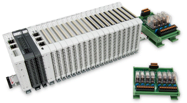
The product is a remote I/O module system that allows users to connect the MELSEC-Q series communication port (Modbus TCP) externally. It includes a gateway, main controller, digital input, digital output, and power supply modules. The main controller manages and dynamically configures I/O parameters. The power module is standard for remote I/Os and users can choose the model or brand of power module they prefer.
Remote I/O Module System Configuration List
The list includes the following:
| Part No. | Specification | Description |
|---|---|---|
| GFGW-RM01N | Modbus TCP-to-Modbus RTU/ASCII, 4 Ports | Gateway |
| GFMS-RM01S | Master Modbus RTU, 1 Port | Main Controller |
| GFDI-RM01N | Digital Input 16 Channel | Digital Input |
| GFDO-RM01N | Digital Output 16 Channel / 0.5A | Digital Output |
| GFPS-0202 | Power 24V / 48W | Power Supply |
| GFPS-0303 | Power 5V / 20W | Power Supply |
Product Gateway Parameter Settings
This section explains how to connect the gateway to the MELSEC-Q series. For detailed information, refer to the MELSEC-Q Series Product Manual. The i-Designer program is used for setup.
i-Designer Program Setup
- Ensure that the module is powered and connected to the gateway module using an Ethernet cable.
- Launch the i-Designer software.
- Select M Series Module Configuration.
- Click on the Setting Module icon.
- Enter the Setting Module page for M-series.
- Select the mode type based on the connected module.
- Click on Connect.
- Set the Gateway Module IP Address. Note: The IP address must be in the same domain as the MELSEC-Q controller.
- Set Gateway Module Operational Modes. Note: Set Group 1 as Slave and set the gateway to use the first set of RS485 port to connect to the main controller (GFMS-RM01N).
MELSEC-Q series Connection Setup
This chapter explains how to use the GX Works2 program to connect the MELSEC-Q series to a gateway module and add a remote I/O module. For detailed information, refer to the MELSEC-Q Series Manual.
MELSEC-Q series Hardware Connections
- The QJ71MT91 module’s Ethernet port is at its bottom center and can be connected to the gateway.
MELSEC-Q series IP Address and Connection Setup
- Launch GX Works 2 and right-click on the Intelligent Function Module menu under Project on the left side.
- Click on New Module to create a QJ71MB91 module.
Simple Program Demonstration using MELSEC-Q series and
- No information provided in the user manual for this section.
Product Usage Instructions
- Connect the gateway to the MELSEC-Q series communication port (Modbus TCP) externally using an Ethernet cable.
- Use the i-Designer program to set up the gateway parameters by following the steps mentioned in section 2.1 of the user manual.
- Use the GX Works2 program to connect the MELSEC-Q series to the gateway module and add a remote I/O module by following the steps mentioned in section 3 of the user manual.
Remote I/O Module System Configuration List
| Part No. | Specification | Description |
| GFGW-RM01N | Modbus TCP-to-Modbus RTU/ASCII, 4 Ports | Gateway |
| GFMS-RM01S | Master Modbus RTU, 1 Port | Main Controller |
| GFDI-RM01N | Digital Input 16 Channel | Digital Input |
| GFDO-RM01N | Digital Output 16 Channel / 0.5A | Digital Output |
| GFPS-0202 | Power 24V / 48W | Power Supply |
| GFPS-0303 | Power 5V / 20W | Power Supply |
Product Description
- The gateway is used externally to connect with MELSEC-Q series’ communication port (Modbus TCP)
- The main controller is in charge of the management and dynamic configuration of I/O parameters and so on.
- The power module is standard for remote I/Os and users can choose the model or brand of power module they prefer.
Gateway Parameter Settings
This section details how to connect a gateway to MELSEC-Q series. For detailed information regarding![]() , please refer to the
, please refer to the ![]() -Series Product Manual
-Series Product Manual
i-Designer Program Setup
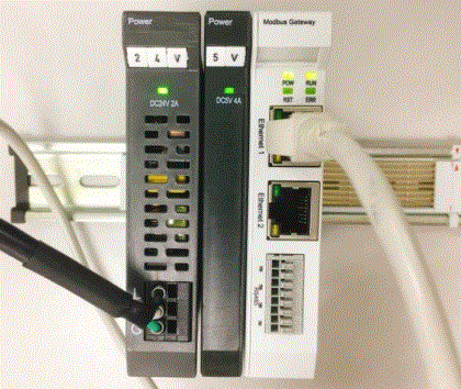
- Make sure that the module is powered and connected to the gateway module using an Ethernet cable

- Click to launch the software
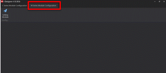
- Select “M Series Module Configuration”
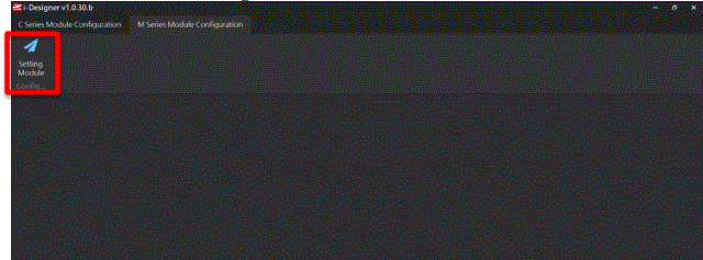
- Click on the “Setting Module” icon
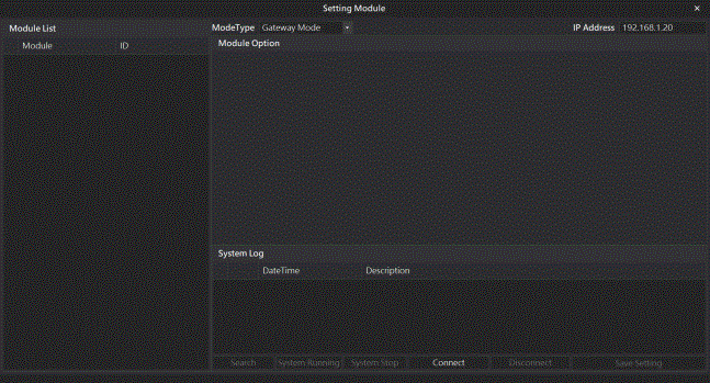
- Enter the “Setting Module” page for M-series
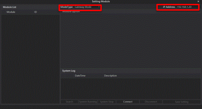
- Select the mode type based on the connected module
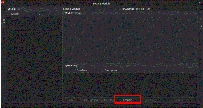
- Click on “Connect”
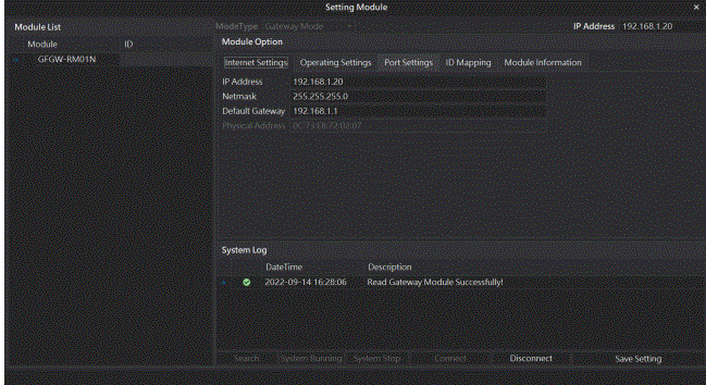
- Gateway Module IP Settings
- Note: The IP address must be in the same domain as the MELSEC-Q controller
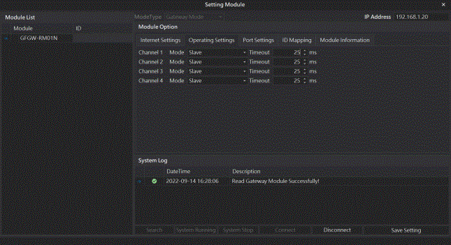
- Note: The IP address must be in the same domain as the MELSEC-Q controller
- Gateway Module Operational Modes
Note: Set Group 1 as Slave and set the gateway to use the first set of RS485 port to connect to the main controller (GFMS-RM01N)
MELSEC-Q series Connection Setup
This chapter explains how to use the GX Works2 program to use the QJ71MT91 module to connect MELSEC-Q series to a gateway module and add a remote I/O module. For detailed information, please refer to the “MELSEC-Q Series Manual
MELSEC-Q series Hardware Connections
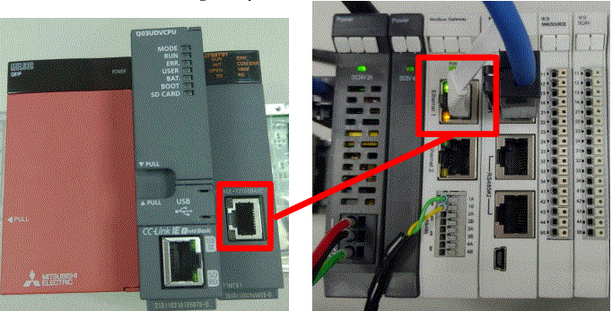
- The QJ71MT91 module’s Ethernet port is at its bottom center and can be connected to the gateway
MELSEC-Q series IP Address and Connection Setup
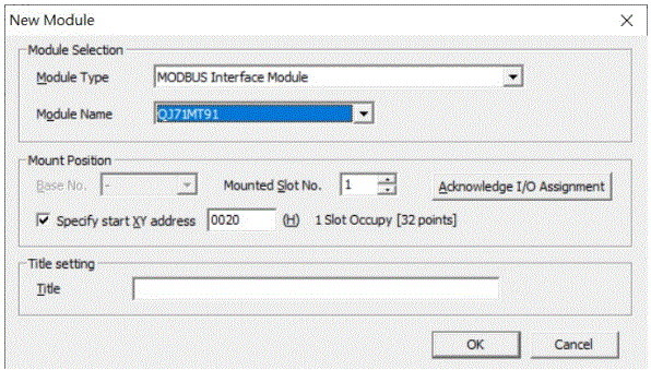
- Launch GX Works 2 and right click on the “Intelligent Function Module” menu under “Project” on the left side. Then click on “New Module” to create a “QJ71MB91” module
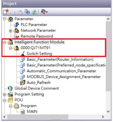
- Launch GX Works 2 and select the “Intelligent Function Module” menu under “Project” on the left side. Then click on “Switch Setting” in the “QJ71MT91” menu
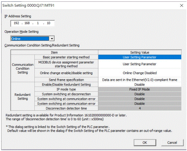
- Set “IP Address” to the same domain as the gateway domain at 192.168.1.XXX.
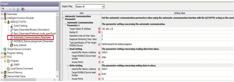
- Click on “Automatic_Communication_Parameter” to set up reading and writing methods
- Ⓐ Target Station IP Address is set by default at ”192.168.1.20”
- Ⓑ The
 station number to be connected
 - Ⓒ From the drop-down menu, select “0505h:Read/Write Holding Registers”
- Ⓓ Set to 1000h
- Ⓓ The Target MODBUS Device Head Number is set to 4096
- Ⓕ Read Points
- Ⓖ Set to 3000h
- H The Target MODBUS Device Head Number is set to 8192
- Ⓘ Write Points
Notes
 first GFDI-RM01N has the register address at 1000(HEX) converted to 4096
 first GFDO-RM01N has the register address at 2000(HEX) converted to 8192
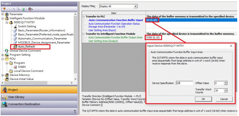
- Click on “Auto_Refresh” to set up the internal register for reading and writing
Simple Program
Simple Program Demonstration using MELSEC-Q series and ![]()

- The
 read register address is 4096, which is D0 for the corresponding internal register of the controller.
 - And the
 write register address is 8192, which is D300 for the corresponding internal register of the controller.
 - Therefore, when you want to control the program, you can just use the internal register to control the writing and reading.
Documents / Resources
 | DAUDIN GFDO-RM01N MELSEC-Q Modbus TCP Connection [pdf] User Manual GFDO-RM01N MELSEC-Q Modbus TCP Connection, GFDO-RM01N, MELSEC-Q Modbus TCP Connection, MELSEC-Q Modbus, Modbus |


