![]()
T86-IO Closed Loop Stepper Driver
User Manual
Shenzhen Rtelligent Mechanical Electrical Technology Co.,ltd
Product overview
Thank you for choosing Rtelligent T series digital stepper servo driver. Stepper servo is a stepper motor scheme formed based on the common open-loop stepper motor in combination with position feedback and servo algorithm, which features high speed, high torque, high precision, low vibration, low heating and no loss of step. Based on TI’s new 32-bit DSP processing chip platform, T series stepper servo driver uses the field-oriented control (FOC) and vector field-weakening control algorithm in the servo driver, which has the performance of surpassing the ordinary stepper in all aspects.
- The built-in PID parameter adjustment function makes the motor better meet the application of different kinds of loads.
- The built-in field-weakening control algorithm makes the motor to reduce the magnetic field characteristics and keep the power at high speed.
- The built-in current vector control function makes the motor have the current characteristic of servo and low heating.
- The built-in micro-stepping command algorithm makes the motor can run while maintaining a stable and low vibration at various speeds.
- The encoder feedback with the built-in 4000 pulse resolution makes the positioning precision increase and never loses the step.
In conclusion, the servo control scheme combined with the characteristics of the stepper motor enables the T series stepper servo driver to better exert the performance of the stepper motor, which can replace the servo application of the same power. It is a new choice of optimal cost performance for automation equipment.
T86-IO driver can set subdivision and other parameters through DIP switch and debugging software. It has protection functions such as voltage, current, and position, and adds alarm output interface. Its input and output control signals are optically isolated.
| Power supply | 20-80 VAC 24 –100 VDC |
| Control precision | 4000 Pulse/r |
| Current control | Servo vector control algorithm |
| Speed settings | DIP switch setting, or debugging software setting |
| Speed range | Conventional 1200 ~ 1500rpm, up to 4000rpm |
| Resonance suppression | Automatically calculate the resonance point and inhibit the IF vibration |
| PID parameter adjustment | Test software to adjust motor PID characteristics |
| Pulse filtering | 2MHz digital signal filter |
| Alarm output | Alarm output of over-current, over-voltage, position error, etc |
We hope that our products with excellent performance can help you to complete the sports control program successfully.
Please read this technical manual before using the products.
Application environment and installation
Environmental requirement
| Item | Rtelligent T86-IO |
| Installation environment | Avoid dust, oil, and corrosive environment |
| Vibration | 0.5G(4.9m/s2 )Max |
| Operating temperature/humidity | 0℃ ~ 45℃ / 90% RH or less (no condensation) |
| Storage and transportation temperature: | -10℃ ~ 70℃ |
| Cooling | Natural cooling / away from the heat source |
| Waterproof grade | IP54 |
Driver installation dimensions

Driver installation requirements
Please install the driver vertically or horizontally, with its front-facing forward, top facing upward to facilitate cooling.
During assembly, avoid drillings and other foreign matters falling inside the driver.
During assembly, please use M3 screw to fix.
When there is vibration source (such as a driller) close to the installation position, please use a vibrating absorber or a vibration-resistant rubber gasket.
When multiple drivers are installed in the control cabinet, please pay attention to reserve enough space for sufficient heat dissipation. If necessary, you can configure cooling fans to ensure good heat dissipation conditions in the control cabinet.
Driver port and connection
Port function description
| Function | Grade | Definition | Remarks |
| Power supply input | AC | Input AC power supply | AC 20-80V DC 24-100V |
| AC | Input AC power supply | ||
| Motor connection | A+ | Positive terminal of phase-A winding | Red |
| A- | Negative terminal of phase-A winding | Yellow | |
| B+ | Positive terminal of phase-B winding | Black | |
| B- | Negative terminal of phase-B winding | Green | |
| Encoder connection | EB+ | Positive terminal of Encoder phase B | Green |
| EB- | Negative terminal of Encoder phase B | Yellow | |
| EA+ | Positive terminal of Encoder phase A | Brown | |
| EA- | Negative terminal of Encoder phase A | White | |
| VCC | Encoder working power 5V positive | Red | |
| GND | Encoder working power 5V ground terminal | Blue | |
| Pulse connection | PUL+ | Start input interface | 24V level |
| PUL- | |||
| D1R+ | Direction input interface | ||
| DIR- | |||
| Enable terminal | ENA+ | Enable control interface | |
| ENA- | |||
| Mann output | ALM+ | Mann output interface | 24V. below |
| ALM- | |||
| In place output | Pend+ | 40mA In place output interface | |
| Pend- |
Power supply input
The power supply of the driver can be both AC power and DC power, and the input voltage range is 20V~80VAC or 24V~100VDC.
Please do not connect to commercial electricity(220VAC) directly!
Power selection reference:
Voltage:
Stepper motor has the characteristics of torque decrease with the increase of motor speed, and the input voltage will affect the amplitude of high-speed torque reduction. Properly increasing the voltage of the input power supply can increase the output torque of the motor at high speed.
Stepper servo has a higher speed and torque output than ordinary stepper. Therefore, if you want to get better high-speed performance, you need to increase the power supply voltage of the driver.
Current:
The working process of the driver is to convert the input high-voltage and low-current power supply into the low-voltage and high-current at both ends of the motor winding. In actual use, the appropriate power supply should be selected according to the motor model, load torque, and other factors.
The effects of regeneration voltage:
When the stepper motor is working, it also retains the characteristics of the generator. When decelerating, the kinetic energy accumulated by the load will be converted into electrical energy and superimposed on the driver circuit and input power supply.
Pay attention to the setting of acceleration and deceleration time to protect the driver or power supply.
When the driver is powered off, you will see the driver’s LED indicator on when the load is pulled to make the motor move, which is also affected by this.
Encoder connection
The T86-IO encoder is A/B differential output and is connected in the corresponding order when used.
| EB+ | EB- | EA+ | EA- | VCC | GND |
| Green | Yellow | Brown | White | Red | Blue |
Rtelligent is equipped with a certain length of encoder cable, Please purchase extension cables of different lengths according to the installation needs.
Motor connection
The matching motor of the T86-IO driver is the corresponding T series stepper servo motor, and its corresponding motor connection order is fixed and unique.

| A+ | Red |
| A- | Yellow |
| B+ | Black |
| B- | Green |
Control signal connection
PUL, DIR Port: connection for start and stop command
| and direction indication | 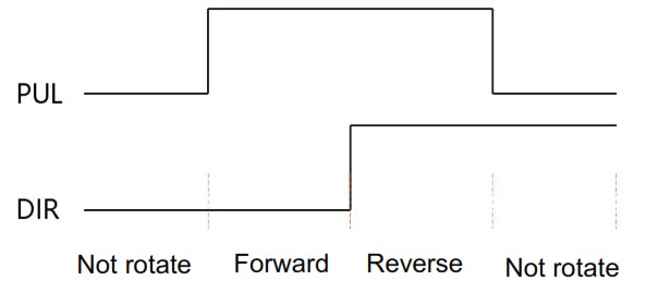 |
| 1. At PUL on and DIR off, the motor is triggered to rotate forward. When PUL is turned off, the motor decelerates and stops. 2. At PUL on and DIR on, the motor is triggered to rotate reverse. When PUL is turned off, the motor decelerates and stops. 3.At PUL off, the motor stops. |
ENA port: enable/disable
When the internal optocoupler is off, the driver outputs current to the motor;
When the internal optocoupler is on, the driver will cut off the current of each phase of the motor to make the motor free, and the step pulse will not be responded.
When the motor is in an error state, it is automatically turned off. The level logic of the enable signal can be set to the opposite.
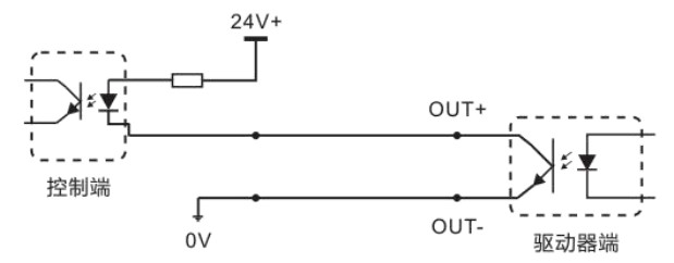
ALM, Pend port: used for alarm and in place output.
The ALM port is used to output the operating status of the driver to an external control circuit. When the driver is in the error state and the normal working state, ALM outputs different optocoupler levels.
The Pend port is used to output the driver in-place signal. When the difference(position deviation) between the pulse command position sent by the upper computer and the current position of the stepper servo motor is less than the set value, the in-place signal is output. The upper computer receives the signal and confirms that the positioning is complete.
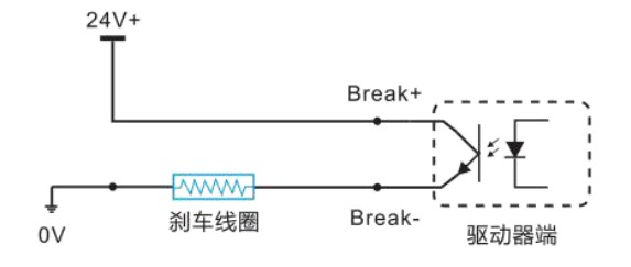
In addition, ALM and Pend ports can be reused as brake control (break) signal through software adjustment, which is used to control the brake switch of stepper servo motor with brake. Since the brake coil is an inductive load, and the coil heating is serious when the motor is running, customers can select special brake controller according to their needs to reduce the brake heating and improve life and reliability.
 Rtelligent provides solutions for dedicated brake controllers, examples are as follows:
RS232 serial port

| S/N | Symbol | Description |
| 1 | NC | |
| 2 | +5V | Positive terminal of power supply |
| 3 | TxD | RS232 transmitting terminal |
| 4 | GND | Ground terminal of power supply |
| 5 | RxD | RS232 receiving terminal |
| 6 | NC |
RS232 serial port is used to connect T86-IO testing software and change other related operating parameters of driver.
The setting of DIP switches and operating parameters

The setting of speed
| Speed | SVV1 | SW2 | SW3 | SW4 | Remarks |
| 100 | on | on | on | on | Other speeds can be customized |
| 150 | off | on | on | on | |
| 200 | on | off | on | on | |
| 250 | off | off | on | on | |
| 300 | on | on | off | on | |
| 400 | off | on | off | on | |
| 500 | on | off | off | on | |
| 600 | off | off | off | on | |
| 700 | on | on | on | off | |
| 800 | off | on | on | off | |
| 900 | on | off | on | off | |
| 1000 | off | off | on | off | |
| 1100 | on | on | off | off | |
| 1200 | off | on | off | off | |
| 1300 | on | off | off | off | |
| 1400 | off | off | off | off |
Motor direction selection
DIP SW5 is used to set the running direction of the motor under the initial pulse. The “off” means that the motor direction is counterclockwise when inputting the initial pulse; The “on” means that the motor direction is clockwise when inputting the initial pulse. The initial pulse is the testing pulse used when developing the driver software; Please refer to the actual running direction of the motor.
Open/closed loop selection
DIP SW8 is used to set the driver control mode.
The “off” means the closed-loop control mode;
The “on” means the open-loop control mode and can be used to test the motor.
Driver working status LED indication
| LED status | Driver status | |
| Green indicator is on for long time | Driver not enabled | |
| Green indicator is flickering | Driver working normally | |
| One green indicator and one red indicator | Driver overcurrent | |
| One green indicator and two red indicators | Driver input power overvoltage | |
| One green indicator and three red indicators | The internal voltage of the driver is wrong | |
| One green and four red indicators | Tracking error exceeds limits | |
| One green and five red indicators | Encoder phase error | |
Common faults and troubleshooting
| Phenomenon | Possible situations | Solutions |
| Motor does not work | Power indicator is off | Check the power supply circuit for normal power supply |
| The motor rotor is locked but the motor does not work | Pulse signal is weak; increase the signal current to 7-16mA | |
| The speed is too slow | Select the right micro-stepping | |
| Driver is protected | Solve the alarm and re-power | |
| Enable signal problem | Pull up or disconnect the enable signal | |
| Command pulse is incorrect | Check whether the upper computer has pulse output | |
| The steering of motor is wrong | The rotary direction of motor is reverse | Adjust the DIP SW5 |
| The motor cable is disconnected | Check the connection | |
| The motor has only one direction | Pulse mode error or DIR port damaged | |
| Alarm indicator is on | The motor connection is wrong | Check the motor connection |
| The motor connection and encoder connection are wrong | Check the sequence of encoder connection | |
| The voltage is too high or too low | Check the power supply | |
| The position or speed is wrong | The signal is disturbed | Eliminate interference for reliable grounding |
| The command input is incorrect | Check the upper computer instructions to ensure the output is correct | |
| The setting of Pulse per revolution is wrong | Check the DIP switch status and correctly connect the switches | |
| Encoder signal is abnormal | Replace the motor and contact the manufacturer | |
| The driver terminal burned up | Short circuit between terminals circuit | Check power polarity or external short |
| Internal resistance between terminals is too large | Check whether there is any solder ball due to excessive addition of solder on the wire connections | |
| The motor is out of tolerance | Acceleration and deceleration time is too short | Reduce command acceleration or increase driver filtering parameters |
| Motor torque is too low | Select the motor with high torque | |
| The load is too heavy | Check the load weight and quality and adjust the mechanical structure | |
| The current of power supply is too low | Replace the appropriate power supply |
Appendix A. Guarantee Clause
A.1 Warranty period: 12 months
We provide quality assurance for one year from the date of delivery and free maintenance service for our products during the warranty period.
A.2 Exclude the following:
- Improper connection, such as the polarity of the power supply is reversed and insert/pull the motor connection when the power supply is connected.
- Beyond electrical and environmental requirements.
- Change the internal device without permission.
A.3 Maintenance process
For maintenance of products, please follow the procedures shown below:
- Contact our customer service staff to get the rework permission.
- The written document of the driver failure phenomenon is attached to the goods, as well as the contact information and mailing methods of the sender.
Mailing address:
Post code:
Tel.:
szruitech.com
Documents / Resources
 | RTELLIGENT T86-IO Closed Loop Stepper Driver [pdf] User Manual T86-IO, Closed Loop Stepper Driver, T86-IO Closed Loop Stepper Driver |


