![]() Command Line Interface
Command Line Interface
User Manual
CLI
Introduction
This manual describes how to control products via their control interface. The Command Line Interface (CLI) enables the hub or hubs to be integrated into a larger system that is controlled by a host computer. A Serial terminal emulator must be installed to be able to use the CLI, and the emulator requires access to the COM port, so no other software, such as LiveViewer, can access the port at the same time. An example emulator that can be used is puTTY which can be downloaded from the following link.
www.putty.org
Commands that are issued via the COM port are referred to as commands. Some settings modified by commands in this document are volatile – that is, the settings are lost when the hub is rebooted or powered off, please see individual commands for detail.
Throughout this manual optional parameters are shown in square brackets: [ ]. ASCII control characters are shown within <> brackets.
This document and commands are subject to change. Data should be parsed such to be tolerant of both upper and lower case, white space, additional new line characters …etc.
You can download the latest version of this manual from our website at the following link.
www.cambrionix.com/cli
2.1. Device location
The system appears as a virtual serial port (also called a VCP). On Microsoft Windows™ , the system will appear as a numbered communication (COM) port. The COM port number can be found by accessing device manager.
On macOS®, a device file is created in the /dev directory. This is of the form/dev/tty.usbserial S where S is an alpha-numeric serial string unique to each device in the Universal Series.
2.2. USB Drivers
Communication to our products is enabled through a virtual COM port, this communication requires USB drivers.
On Windows 7 or later, a driver may automatically be installed (if Windows is configured to download drivers from the internet automatically). If this is not the case, the driver can be downloaded from www.ftdichip.com. The VCP drivers are required. For Linux® or Mac® computers, the default OS drivers should be used.
2.3. Communication Settings
The default communications settings are as below.
| Communication setting | Value |
| Number of bits per second (baud) | 115200 |
| Number of data bits | 8 |
| Parity | None |
| Number of stop bits | 1 |
| Flow control | None |
ANSI terminal emulation should be selected. Command sent must be terminated with Lines received by the hub are terminated with
 The hub will accept back-to-back commands, however, the host computer should wait for a response before issuing a new command.
| CAUTION | |
| The hub may become unresponsive For serial communications you must wait for a response from any commands before issuing a new command. Failure to do so can cause the hub to become unresponsive and require a full power reset. |
2.4. Boot text and command prompt
At boot, the hub will issue a string of ANSI escape sequences to reset an attached terminal emulator.
The title block follows this, then a command prompt.
The command prompt received is as below Except in boot mode where it is as below
 To reach a new boot prompt, send <ETX>. This cancels any partial command string.
2.5. Products and their Firmware
Below is a list of products, their part numbers and the Firmware type it uses.
| Firmware | Part Number | Product Name |
| Universal | PP15S | PowerPad15S |
| Universal | PP15C | PowerPad15C |
| Universal | PP8S | PowerPad8S |
| Universal | SS15 | SuperSync15 |
| Universal | TS3-16 | ThunderSync3-16 |
| TS3-C10 | TS3-C10 | ThunderSync3-C10 |
| Universal | U16S Spade | U16S Spade |
| Universal | U8S | U8S |
| PowerDelivery | PDS-C4 | PDSync-C4 |
| Universal | ModIT-Max | ModIT-Max |
| MotorControl | Motor control board | ModIT-Max |
2.6. Command structure
Each command follows the below format. The command will need to be entered first, if no parameters exist for the command then this will need to be followed immediately by <CR> and <LF> to send the command.
Not every command has mandatory parameters but if they are applicable then these will need to be entered for the command to work, once the command and mandatory parameters are entered then <CR> and <LF> will be required to signify the end of a command.
Optional parameters are shown inside square brackets e.g. [port]. These do not need to be entered for the command to be sent, but if they are included they will need to be followed by <CR> and <LF> to signify the end of a command.
2.7. Response structure
Each command will receive it’s specific response followed by <CR><LF>, a command prompt and then a space. The response is terminated as shown below.
Some command responses are “live” meaning there will be a continuous response from the product until the command is cancelled by sending an <ETX> command. In these instances you will not receive the standard response as above until <ETX> command has been sent. If you disconnect the product it will not stop the data stream and reconnecting will result in the continuation of the data stream.
Commands
Below is a list of commands that are supported by all products
| Command | Description |
| bd | Product description |
| cef | Clear error flags |
| cls | Clear terminal screen |
| crf | Clear rebooted flag |
| health | Show voltages, temperature, errors and boot flag |
| host | Show if USB host is present, and set mode change |
| id | Show id string |
| l | Live view (Periodically sends responses on the current state of the product) |
| ledb | Sets the LED pattern using a bit format |
| leds | Sets the LED pattern using a string format |
| limits | Show voltage and temperature limits |
| loge | Log state and events |
| mode | Sets the mode for one or more ports |
| reboot | Reboots the product |
| remote | Enter or exit mode where LEDs are controlled manually or automatically |
| sef | Set error flags |
| state | Show state for one or more ports |
| system | Show system hardware and firmware information |
Below is a table of commands specific to the Universal Firmware
| Command | Description |
| beep | Makes the product beep |
| clcd | Clear LCD |
| en_profile | Enables or disables profile |
| get_profiles | Get list of profiles associated with a port |
| keys | Read key click event flags |
| lcd | Write a string to the LCD display |
| list_profiles | List all profiles on system |
| logc | Log current |
| sec | Set or get security mode |
| serial_speed | Change serial interface speed |
| set_delays | Change internal delays |
| set_profiles | Set profiles associated with a port |
Below is a list of commands specific to the PD Sync and TS3-C10 Firmware
| Command | Description |
| detail | show state for one or more ports |
| logp | Log current |
| power | set product max power or get product power for one or more ports |
| qcmode | set quick charge mode for one or more ports. |
Below is a list of commands specific to the Motor Control Firmware
| Command | Description |
| gate | Open, close or stop gates |
| keyswitch | Show state of keyswitch |
| proxy | Distinguish commands meant for Motorcontrol board |
| stall | Set stall current for motors, |
| rgb | Set LEDs to RGB override enable on ports |
| rgb_led | Set LEDs on ports to RGBA value in hex |
3.1. Notes
- Some products don’t support all the commands. See the Supported Products section for
- All commands meant for the Motor control board must be prefixed with the proxy
3.2. bd (Product Description)
The bd command provides a description of the architecture of the product. This includes all upstreand downstream ports. This is to provide external software the architecture of the USB connection tree.
Syntax: (see ‘Command structure)
Response: (see Response structure)
Name value pairs indicating the presence of features of the product. This is followed by a description of each USB hub in turn, listing what is attached to each port of that hub. Each port of a hub will be attached to a charging port, an expansion port, a downstream hub, a USB device or is unused.
The features are indicated by these entries:
| Parameter | Value |
| Ports | The number of USB ports |
| Sync | A ‘1’ indicates the product provides sync capability |
| Temp | A ‘1’ indicates the product can measure temperature |
| EXTPSU | A ‘1’ indicates the product is supplied with an external PSU that is greater than 5V |
The attachment section can have the following entries, all indices are 1 based:
| Parameter | Value | Description |
| Nodes | n | A number indicating the number of nodes this description set includes. A node will be either a USB hub or a USB controller. |
| Node i Type | type | i is an index indicating which node this is. type is an entry from the Node Table below. |
| Node i Ports | n | A number indicating how many ports this node has. |
| Hub <i> Port <p> | Hub <j> | The USB hub <i> has a down-stream hub <j> connected to its port <p> |
| Control Port | The USB hub <i> has the USB serial port attached to port <p> | |
| Expansion Port <e> | The USB hub <i> has an expansion port attached to port <p> | |
| Port <c> | The USB hub <i> has the charging port <c> attached to port <p> | |
| Optional Hub <j> | The USB hub <i> may have a down-stream hub <j> connected to its port <p> but this is optional so may not be fitted | |
| Turbo Hub <j> | The USB hub <i> has a USB hub capable of operating in Turbo mode attached to port <p> | |
| USB3 Hub <j> | The USB hub <i> has a USB 3.x hub attached to port <p> | |
| Unused Port | The USB hub <i> has nothing attached to its port <p> |
Node type can be one of the following:
| Node Type | Description |
| Hub j | A USB 2.0 hub index j |
| Optional Hub j | A USB hub that may be fitted, index j |
| Root r | A USB controller with a root hub which also means the USB bus number will change |
| Turbo Hub j | A USB hub capable of operating in Turbo mode with index j |
| USB3 Hub j | A USB 3.x hub with index j |
Example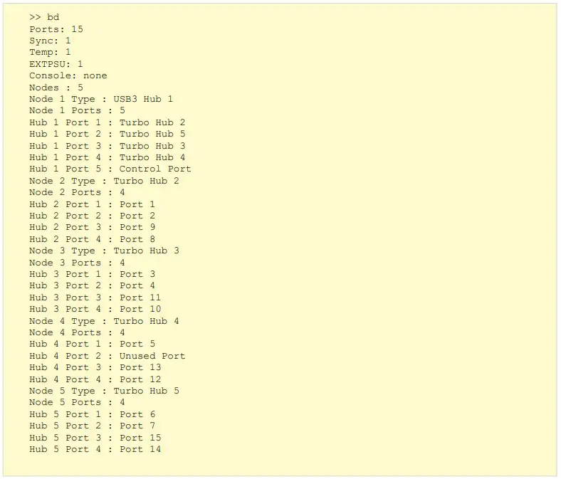 3.3 cef (Clear error flags)
The CLI has error flags which will signify if a specific error has occurred. The flags will only be cleared by using the cef command or through a product reset or power on / off cycle.
| “UV” | Under-voltage event occurred |
| “OV” | Over-voltage event occurred |
| “OT” | Over-temperature (over-heat) event occurred |
If the error condition persists, the hub will set the flag again after it is cleared.
Syntax: (see Command structure)
Response: (see Response structure) 3.4. cls (Clear screen)
Sends ANSI escape sequences to clear and reset the terminal screen.
Syntax: (see Command structure) Response: (see Response structure)
3.5. crf (Clear rebooted flag)
The rebooted flag is to inform you if the hub has rebooted in between commands and can be cleared using the crf command.
If the rebooted flag is found to be set, then previous commands changing the volatile settings will have been lost.
Syntax: (see Command structure) Response: (see Response structure)
3.6. health (System health)
The health command displays the supply voltages, PCB temperature, error flags and the rebooted flag.
Syntax: (see Command structure)
Response: (see Response structure)
parameter: value pairs, one pair per row.
| Parameter | Description | Value | |
| Voltage Now | Present supply voltage | ||
| Voltage Min | Lowest supply voltage seen | ||
| Voltage Max | Highest supply voltage seen | ||
| Voltage Flags | List of voltage supply rail error flags, separated by spaces | No flags: voltage is acceptable | |
| UV | Under-voltage event occurred | ||
| OV | Over-voltage event occurred | ||
| Temperature Now | PCB temperature, °C | >100 C | Temperature is above 100°C |
| <0.0 C | Temperature is below 0°C | ||
| tt.t C | Temperature, e.g. 32.2°C | ||
| Temperature Min | Lowest PCB temperature seen, °C | <0.0 C | Temperature is below 0°C |
| Temperature Max | Highest PCB temperature seen, °C | >100 C | Temperature is above 100°C |
| Temperature Flags | Temperature error flags | No flags: temperature is acceptable | |
| OT | Over-temperature (over-heat) event occurred | ||
| Rebooted Flag | Used to detect if system has booted | R | System has booted or rebooted |
| Flag cleared using crf command | |||
Example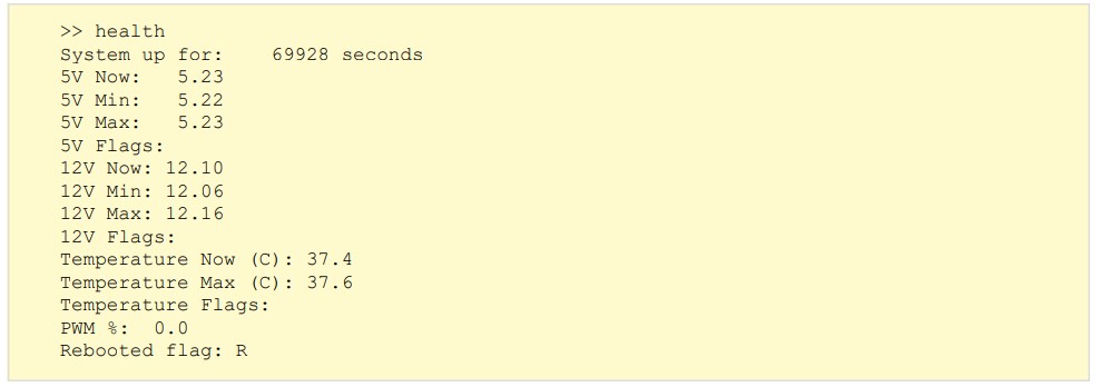 *output from a SS15
3.7. host (Host detection)
The hub monitors the host USB socket for an attached host computer. In auto mode if the product detects a host it will change to sync mode.
The host command can be used to determine if a host computer is attached. It can also be used to prevent the hub from automatically changing modes.
Syntax: (see Command structure)
Table for mode in the Universal Firmware
| Mode | Description |
| auto | The mode of all populated ports changes automatically when a host is connected or disconnected |
| manual | Only commands can be used to change modes. The presence or absence of a host will not change the mode |
Table for mode in the PDSync and TS3-C10 Firmware
| Mode | Description |
| auto | The ports will enable sync connectivity as the host comes and goes. Charging is always enabled unless the port is turned off. |
| off | If the host is no longer detected, all charging ports will be turned off. |
Response if parameter is supplied: (see Response structure)
Response if no parameter is supplied:
| Parameter | Description | Value |
| Present | Whether a host is present or not | Yes / No |
| Mode change | The mode the hub is in | Auto /Manual |
Table for present in all firmware
| Present | Description |
| yes | host is detected |
| no | host is not detected |
Notes
- The presence of the host computer is still reported if the mode is set to manual.
- On charge only products the host command is present, but as the products are charge only and cannot obtain device information the command is redundant.
- Only the U8S can report the host to be not present as it is the only product that has a separate control and host connection.
- The default host mode is auto for all products.
Examples
To set host mode to manual: To determine if a host is present, and the get the mode:
And with a host attached: 3.8. id (Product identity)
The id command is used to identify the product and also provides some basic information about the firmware running on the product.
Syntax: (see Command structure) Response: (see Response structure)
A single line of text containing multiple name:value pairs separated by commas, that can be used to identify the product.
| Name | Value |
| mfr | Manufacturer string (eg, cambrionix) |
| mode | A string to describe which operating mode the firmware is in (eg, main) |
| hw | The part number of the hardware Part numbers) |
| hwid | A hexadecimal value used internally to identify the product (eg, 0x13) |
| fw | A pseudo number representing the firmware revision (eg, 1.68) |
| bl | A pseudo number representing the bootloader revision (eg, 0.15) |
| sn | A serial number. If not used will show all zeros (eg, 000000) |
| group | Used on some products to order firmware updates which is useful when updating products that are daisy-chained together so that down-stream products are updated and rebooted first. |
| fc | Firmware Code is used to denote which firmware type the product accepts |
Example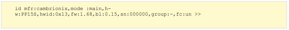
3.9. l (Live view)
Live view provides a continuous stream of data to view the port states and flags. Ports can be commanded using single key presses as per the table below.
Syntax (see Command structure) Live view is designed to be interactive using a terminal. It makes extensive use of ANSI escape sequences to control the cursor position. Do not try to script the control of the live view.
The terminal size (rows, columns) must be large enough or the display will be corrupted. The hub attempts to set the number of rows and columns of the terminal when entering live viewmode.
Commands :
Type the below commands to interact with live view.
Select a port by typing a 2-digit port number (e.g. 01) to toggle all ports use /
| Command | Description |
| / | Toggle all ports |
| o | Turn port off |
| c | Turn port to charge only |
| s | Turn port to sync mode |
| q /<ETX> | Quit live view |
Example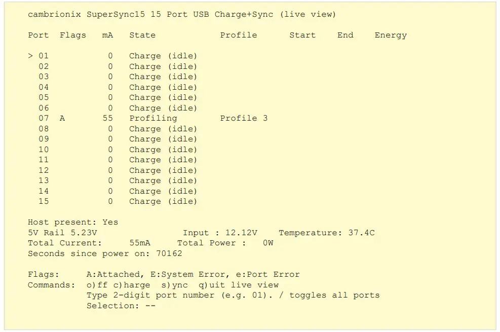
3.10. ledb (LED bit flash pattern)
The ledb command can be used to assign a flash bit pattern to an individual LED.
Syntax: (see Command structure)
 port: is the port number, starting at 1
row: is the LED row number, starting at 1. Typically these are arranged as follows:
| Row | LED Function |
| 1 | Charged |
| 2 | Charging |
| 3 | Sync mode |
ptn: can be specified as decimal (range 0..255), hexadecimal (range 00h to ffh) or binary (range 00000000b to 11111111b). Hexadecimal number must end with ‘h’. Binary numbers must end with ‘b’. More significant digits can be omitted for all radices. For example, ‘0b’ is the same as ‘00000000b’.
Hexadecimal numbers are not case-sensitive. The valid pattern characters can be seen in the LED control
Control
using the [H | R] optional parameters
| Parameter | Description |
| H | takes over control of the LED without a remote command |
| R | releases control of the LED back to normal operation. |
Example
To flash the charging LED on port 8 at 50/50 duty cycle, use: To turn on the port 1 charged LED continuously (i.e. no flashing):
 To turn off the port 1 sync LED:
Notes
- When no LEDs are present the commands is not found.
- The LED state is not re-established when remote mode is exited and then re-entered.
3.11. leds (LED string flash pattern)
The leds command can be used to assign a string of flash patterns to one row of LEDs. This is much faster for controlling an entire row of LEDs. Just three uses of the leds command can set all the LEDs on the system.
Syntax: (see Command structure) row: is address as for ledb above.
[ptnstr] is a string of characters, one per port, starting at port 1. Each character represents a different flash pattern to be assigned to the port. A string of characters will assign flash patterns to the ports.
The valid pattern characters can be seen in the LED control
Example
To set up the following flash pattern on the row containing LED one:
| Port | LED function |
| 1 | Unchanged |
| 2 | On |
| 3 | Flash fast |
| 4 | Single pulse |
| 5 | Off |
| 6 | On continuously |
| 7 | On continuously |
| 8 | Unchanged |
Issue the command: Note that the first LED (port 1) needed to be skipped using the x character. Port 8 was not altered as the pattern string only contained 7 characters.
Notes
- When no LEDs are present the commands is not found.
- The LED state is not re-established when remote mode is exited and then re-entered.
3.12. limits (system limits)
To show the limits (thresholds) at which the under-voltage, over-voltage and over-temperature errors are triggered, issue the limits command.
Syntax (see Command structure)
Example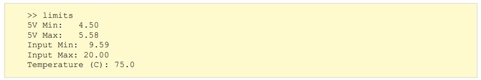 *output from SS15
Notes
- The limits are fixed in the firmware and cannot be changed by a command.
- The measurements are sampled every 1ms. The voltages must be over or under voltage for 20ms before a flag is raised.
- The temperature is measured every 10ms. A running average of 32 samples are used to give the result.
- If the downstream voltage is sampled twice in a row outside product specifications then the ports will be shutoff
3.13. logc (Log port current)
For the Universal firmware the logc command is used to display the current for all ports at a pre-set time interval. Alongside current temperature and fan speed.
The logging for both instances can be stopped by sending q or <ETX>.
Universal Firmware Syntax: (see Command structure) seconds is the interval between responses in the range 1..32767
Response: (see Response structure)
CSV (comma separated values).
Example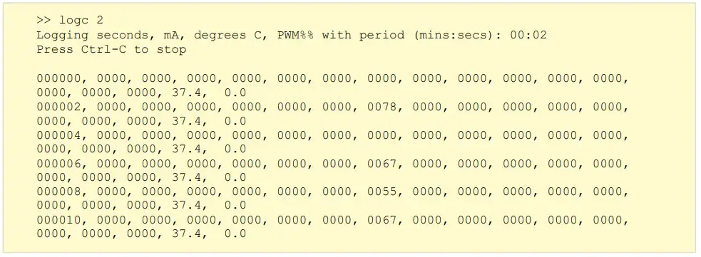 Notes
Notes
- The parameter is specified in seconds, but is confirmed as minutes:seconds for convenience:
- Current logging works in both charge and sync modes.
- The output is rounded to 1mA prior to display
3.14. logp (Log port power)
For the PDSync and TS3-C10 firmware the logp command is used to display the current and voltage for all ports at a pre-set time interval.
The logging for both instances can be stopped by pressing q or CTRL C.
Syntax: (see Command structure) [seconds] is the interval between responses in the range 1..32767
Response: (see Response structure)
CSV (comma separated values).
Example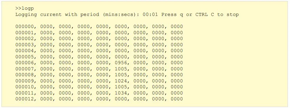
Notes
- The parameter is specified in seconds, but is confirmed as minutes:seconds for convenience:
- Current logging works in both charge and sync modes.
- The output is rounded to 1mA prior to display
3.15. loge (Log events)
The loge command is used to report port status change events and periodically report the state of all ports.
The logging is stopped by sending <ETX>
Syntax: (see Command structure) [seconds] is the interval between responses in the range 0..32767
Response: (see Response structure)
CSV (comma separated values).
Example
Here is a device being attached to port 4, left for 6 seconds, and then removed:
Notes
- Commands are accepted while in this mode but commands are not echoed and the command prompt is not issued.
- If a seconds value of ‘0’ is specified then the periodic reporting is disabled and only port status change events will be reported. If no seconds parameter is supplied a default value of 60s will be used.
- A time stamp in seconds is output before each event or periodic report the time stamp is the time the hub is switched on.
3.16. mode (Hub mode)
Each port can be placed into one of four modes by using the mode command.
Syntax: (see Command structure)
| Parameter | Description |
| m | A valid mode character |
| p | The port number |
| cp | The charging profile |
Response: (see ‘Response structure)
mode parameters for Universal Firmware
| Parameter | Description | Value |
| Charge | The port is readied for charging a device, and can detect if a device is attached or detached. If a device is attached, the charger profiles enabled for that port are tried one by one. Then the device is charged using the profile that yielded the highest current. During the above, the port is disconnected from the host USB bus. | s |
| Sync | The port is attached to the host USB bus via a USB hub. The device may draw charging current from VBUS depending on the device capabilities. | b |
| Biased | Port is detected but no charging or syncing will take place. | o |
| Off | Power to the port is removed. No charging occurs. No device attach or detach detection is possible. | c |
mode parameters for PDSync and TS3-C10 Firmware
| Parameter | Description | Value |
| Sync | The device can charge whilst communicating with the host connected to the hub. | c |
| Off | Power (VBUS) to the port is removed. No charging occurs. No device attach or detach detection is possible. | o |
The port parameter
[p], is optional. It can be used to specify the port number. If left blank, all ports are affected by the command.
The charging profile parameter
[cp] is optional but can only be used when putting a single port into charge mode. If specified then that port will directly enter charge mode using the chosen profile.
| Profile paramete | Description |
| 0 | Intelligent charging algorithmwhich will select a profile 1-6 |
| 1 | 2.1A (Apple and others with short detection time) |
| 2 | BC1.2 Standard (This covers the majority of Android phones and other devices) |
| 3 | Samsung |
| 4 | 2.1A (Apple and others with long detection time) |
| 5 | 1.0A (Typically used by Apple) |
| 6 | 2.4A (Typically used by Apple) |
Examples
To turn off all ports: To put just port 2 in charge mode:

To put just port 4 in charge mode using profile 1:![]()
3.17. Reboot (reboot the product)
Reboots the product.
Syntax: (see Command structure) If the watchdog parameter is included then the systemwill lock into an infinite, unresponsive loop whilst the watchdog timer expires. The expiration takes several seconds, after which the systemwill reboot.
If the reboot command is issued without a parameter, the reboot command is executed immediately.
Response: (see ‘Response structure) The reboot command is a soft reset which will only affect software. To perform a full product reset you will need to power-cycle the hub.
Rebooting sets the ‘R’ (rebooted) flag, which is reported by the health and state commands.
3.18. remote (Remote control)
Some products have interface devices such as indicators, switches and displays which can be used to interact with the hub directly. The function of these interfaces can be controlled via commands. This command disables normal function, and allows control via commands instead.
Entering remote control mode
The indicators will be turned off when entering remote control mode. The display will be unaffected and previous text will remain. Use clcd to clear the display. To disable the console control from the firmware, and allow it to be controlled via commands, issue the remote command without parameters:
Syntax: (see Command structure) To leave remote control mode, and allow the console to be controlled by the firmware, issue an exit command parameter.
| Parameteexit | Description |
| exit | The LEDs will be reset and the LCD cleared when leaving remote control mode. |
| kexit | Tells the hub to enter remote control mode, but exit automatically when a console key is pressed: |
Notes
- In remote kexit mode, the keys command will not return key press events.
- You can move from remote mode into remote kexit mode, and vice-versa.
- Charging, syncing and security still operate in remote mode. However, their status will not be reported to the console, and the user will need to poll the status flags (using the state and health commands) to determine the system state.
- If the keys, lcd, clcd, leds or ledb commands are issued when not in remote or remote kexit mode, then an error message will be shown, and the command will not be executed.
3.19. sef (Set Error flags)
It can be useful to set the error flags to examine the system behaviour when an error occurs.
Syntax: (see Command structure)
 flags is one or more of the below parameters, when sending multiple flags a space is required between each parameter.
| Parameter | Description |
| 3UV | 3V rail under-voltage |
| 3OV | 3V rail over-voltage |
| 5UV | 5V rail under-voltage |
| 5OV | 5V rail over-voltage |
| 12UV | 12V rail under-voltage |
| 12OV | 12V rail over-voltage |
| OT | PCB over-temperature |
Example
To set the 5UV and OT flags:
Notes
- Calling sef without parameters is valid, and sets no error flags.
- Error flags may be set using sef on any product even if the flag is not relevant to the hardware.
3.20. state (List port state)
After a port is placed into a particular mode (e.g. charge mode) it can transition into a number of states. The state command is used to list the state of each port. It also shows the current being delivered to the device, any error flags, and the charge profile employed.
Syntax: (see Command structure)![]() [p] is the port number.
[p] is the port number.
Response: (see Response structure)
Comma separated parameters, one row per port.
Row format: p, current_mA, flags, profile_id, time_charging,time_charged,energy
| Parameter | Description |
| p | The port number pertaining to the row |
| current_mA | Current being delivered to the mobile device, in mA (milliamperes) |
| flags | See below tables |
| profile_id T | The unique profile ID number. “0” if not charging or profiling |
| time_charging | Time in seconds the port has been charging |
| time_charged | Time in seconds that the port has been charged for ( x means not valid yet). |
| energy | Energy the device has consumed in watthours ( calculated every second) |
Note : See product manual for current measurement resolution.
Flags for the Universal firmware range
| List of case-sensitive flag characters, separated by spaces. O, S, B, I, P, C, F are mutually exclusive. A, D are mutually exclusive. | |
| Flag | Description |
| O | Port is in OFF mode |
| S | Port is in SYNC mode |
| B | Port is in Biased mode |
| I | Port is in charge mode, and is IDLE |
| P | Port is in charge mode, and is PROFILING |
| C | Port is in charge mode, and is CHARGING |
| F | Port is in charge mode, and is has FINISHED charging |
| A | Device is ATTACHED to this port |
| D | No device is attached to this port. Port is DETACHED |
| T | Device has been stolen from port: THEFT |
| E | ERRORs are present. See health command |
| R | System has REBOOTED. See crf command |
| r | Vbus is being reset during mode change |
Flags for the PDSync and TS3-C10 firmware range
3 flags are always returned for the Powerync firmware
| List of case-sensitive flag characters, separated by spaces. Flags may mean different things in different columns | |
| 1st flag | Description |
| A | Device is ATTACHED to this port |
| D | No device is attached to this port. Port is DETACHED |
| P | Port has established a PD contract with device |
| C | Cable has non-type-C connector at far end, no device detected |
| 2nd flag | |
| I | Port is IDLE |
| S | Port is the host port and is connected |
| C | Port is CHARGING |
| F | Port has FINISHED charging |
| O | Port is in OFF mode |
| c | Power is enabled on port but no device is detected |
| 3rd flag | |
| _ | Quick charge mode is disallowed |
| + | Quick charge mode is allowed but not enabled |
| q | Quick charge mode is enabled but not in use |
| Q | Quick charge mode is in use |
Flags for the Motor Control firmware range
Case sensitive flag characters. One of o, O, c, C, U will always be present. T and S are only present when their condition is detected.
| Flag | Description |
| o | Gate is opening |
| O | Gate is open |
| c | Gate is closing |
| C | Gate is closed |
| U | Gate position is unknown, neither open nor closed and not moving |
| S | A stall condition was detected for this gate when it was last commanded to move |
| T | A timeout condition was detected for this gate when it was last commanded to move. ie the gate did not finish moving in a reasonable time nor did it stall. |
Examples
A device connected to port 5, which is charging at 1044mA using profile_id 1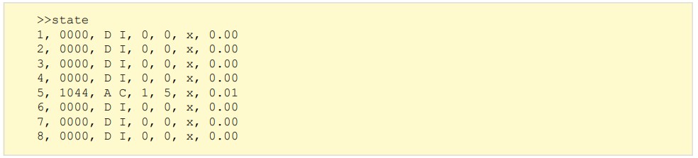 Another device attached to port 8. This is being profiled using profile_id 2 prior to charging:
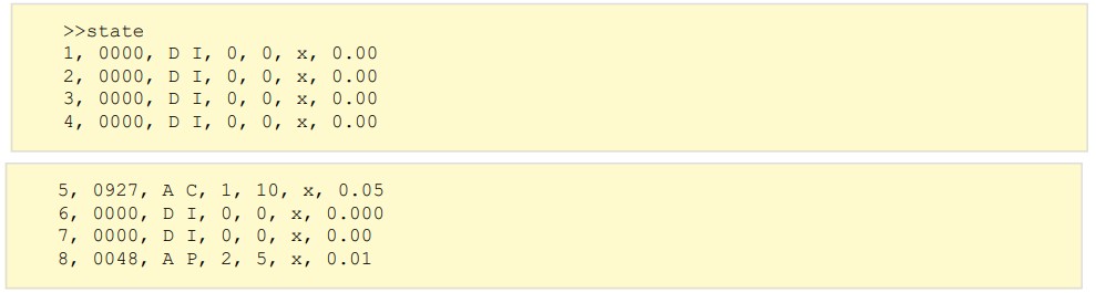 A global system error reported by the EE flag:
 3.21. system (View system parameters)
To view system parameters, issue the system command.
Syntax: (see Command structure) Response: (see Response structure)
First row: system title text.
Subsequent rows: parameter:value pairs, one pair per row.
| Parameter | Description | Possible values |
| Hardware | Part number | |
| Firmware | Firmware version string | In a “n.nn” format, n is a decimal number 0..9 |
| Compiled | Release time and date of the Firmware | |
| Group | Group letter read from PCB jumpers | 1 character, 16 values: “-”, “A” .. “O” “-”means no group jumper is fitted |
| Panel ID | Panel ID number of front panel product | “None” if no panel was detected Otherwise “0” .. “15” |
| LCD | Presence of LCD display | “Absent” or “Present” If product can support an LCD |
Notes
- The system title text may change across firmware releases.
- The ‘Panel ID’ is updated at power-up or reboot.
- The ‘LCD’ parameter can only become ‘Present’ at power-up or reboot. It can become ‘Absent’ during run-time if the LCD is no longer detected. Only applicable to products with removable displays.
3.22. beep (Make product beep)
Makes the sounder beep for a specified amount of time. The beep is performed as a background task – so the system can process other commands whilst the beep is produced.
Syntax: (see Command structure)
| Parameter | Description |
| ms | the length of beep in milliseconds (range 0..32767) |
Response: (see Response structure) Notes
Notes
- The time [ms] has a resolution of 10ms
- A beep will not be interrupted by a shorter or zero-length beep.
- The beep from an alarm is overridden by the continuous tone from a beep command. when the continuous beep completes, the systemwill return to the alarm beep.
- Sending <BEL> from the terminal will cause a short beep to be generated.
- Beeps are only audible on products with sounders fitted.
3.23. clcd (Clear LCD)
The lcd is cleared by using the clcd command.
Syntax: (see Command structure) Response: (see Response structure)
Notes
- This is only applicable to products fitted with displays.
3.24. get_profiles (get port profiles)
To get the profiles assigned to a port, use the get_profiles command. For more information on profiles see Charging profiles
Syntax: (see Command structure) p: is the port number
Response: (see Response structure’)
Port profiles are listed and defined whether they are enabled or disabled
Example
To get the profiles assigned to port 1: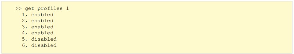 3.25. set_profiles (set port profiles)
To assign profiles to an individual port, use the set_profiles command. For more information on profiles see Charging profiles
Syntax: (see Command structure)
| Parameter | Description |
| p | Port number |
| cp | Charging profile |
To assign all system profiles to a port, issue set_profiles without a list of profiles.
Response: (see Response structure) Example
To set profiles 2 and 3 for port 5: To assign all profiles to port 8:
Notes
- Use get_profiles to obtain list of profiles set on each port.
3.26. list_profiles (List global profiles)
The list of profiles can be obtained by using the list_profiles command: For more information on profiles see Charging profiles
Syntax: (see Command structure) Response: (see Response structure)
Each profile listed has 2 parameters separated by a comma: profile_id, enabled_flag.
The profile_id is a unique number that always corresponds to one profile type. It is a positive integer starting at 1. A profile_id of 0 is reserved for when the absence of a profile is to be indicated.
enabled_flag can be enabled or disabled depending on whether the profile is active on the product.
Example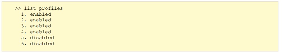 3.27. en_profile (Enable / disable profiles)
The en_profile command is used to enable and disable each profile. The effect applies to all ports.
Syntax: (see Command structure)
| Parameter | Description | Value |
| i | Profile parameter | see below table |
| e | Enable flag | 1 = enabled 0 = disabled |
| Profile parameter | Description |
| 0 | Intelligent charging algorithmwhich will select a profile 1-6 |
| 1 | 2.1A (Apple and others with short detection time) |
| 2 | BC1.2 Standard (This covers the majority of Android phones and other devices) |
| 3 | Samsung |
| 4 | 2.1A (Apple and others with long detection time) |
| 5 | 1.0A (Typically used by Apple) |
| 6 | 2.4A (Typically used by Apple) |
Response: (see Response structure)
Example
To disable a profile for all ports use the command: Operation with no enabled profiles
If all profiles for a port are disabled, the port will transition into the Biased port state. This permits device attach and detach detection to work, but no charging will occur. Security (theft detection) will still operate if all profiles are disabled, as will the attach (AA) and detach (DD) flags reported by the state command.
Notes
- This command has an immediate effect. If the command is issued whilst a port is profiling, then the command will only have an effect if that profile has not yet been reached.
3.28. keys (Key states)
The product may be fitted with up to three buttons. When a button is pressed, a key ‘click’ flag is set.
This flag remains set until it is read. To read the key click flags, use the keys command. The result is a comma-separated list, with one flag per key:
Syntax: (see Command structure)![]()
Keys A, B and C are listed respectively. A ‘1’ means the key has been pressed since the keys command was last called. The flags are cleared after keys is run:
Notes
- The keys command only works in remote mode. It does not work in remote kexit mode
- This command will only work on products with buttons installed.
3.29. lcd (Write to the LCD)
If an LCD is attached, it can be written to by using this command.
Syntax: (see ‘Command structure)
| Parameter | Description |
| row | 0 is the first row, 1 is for the second row |
| col | The column number, starting at 0 |
| string | Displayed on the LCD. It may contain spaces before, within and after. |
Example
To write “Hello, world” on the far left of the second row: Displaying Icons
As well as ASCII characters, the LCD can display several custom icons. These are accessed by sending the escape sequence <ESC> c, where c is the character ‘1’ .. ‘8’:
| c | Icon |
| 1 | Empty battery |
| 2 | Continuously animated battery |
| 3 | Cambrionix filled ‘o’ glyph |
| 4 | Full battery |
| 5 | Padlock |
| 6 | Egg timer |
| 7 | Custom numeral 1 (aligned to right of bitmap) |
| 8 | Custom numeral 1 (aligned to middle of bitmap) |
3.30. sec (Device security)
The product can log if a device was unexpectedly removed from a port. The sec command can be used to put all ports into an ‘armed’ security state. If a device is removed in the armed state, then an alarm can be triggered, and the T flag is shown.
Syntax: (see Command structure) Response to no parameters: (see Response structure)
 Response to arm|disarm parameter: (see Response structure)
![]() Examples
Examples
To arm the system:
To disarm the system: To obtain the armed state:
Notes
- If theft detection is needed, but no device charging or syncing is desired, set the ports to Biased mode. If using Biased mode and the device battery runs out then the alarmwill be raised
- To clear all theft bits and silence a sounding alarm, disarm then re-arm the system.
3.31. serial_speed (Set serial speed)
Sets the serial speed.
Syntax: (see Command structure)
| Parameter | Description |
| test | Test whether the product supports an increase in serial speed from current speed |
| fast | Increase serial speed |
| slow | Reduce serial speed |
Response: (see Response structure)
| Response | Description |
| OK | The product supports an increase in speed |
| Error | The product does not support an increase in speed |
You should flush the serial buffer after the first “serial_speed fast“ before the speed is changed to 1Mbaud. If during operation at 1Mbaud any serial errors are detected the speed is automatically dropped to 115200baud without warning. The host code must be aware of this and take suitable action. If the link regularly fails do not to try increase the speed again.
Example
To increase the serial speed to 1Mbaud use the following sequence: If any error is detected in the above sequence the speed increase won’t occur or will be reset.
Before exiting the host should return the speed back to 115200baud with the following command Failure to do so will result in the first characters being lost until the hub detects the incorrect baud rate as serial errors and drops back to 115200baud.
3.32. set_delays (Set delays)
Sets internal delays
Syntax: (see Command structure)
| Parameter | Description | Default values |
| port_reset_ delay_ms | Time left unpowered when changing modes. (ms) | 400 |
| attach_blanking_ ms | Time device attach detection will be delayed to avoid a quick insert and removal. (ms) | 2000 |
| deattach_count | Reserved for future use. | 30 |
| deattach_sync_ count | A number value to set the depth of filtering a deattach event in sync mode | 14 |
Response: (see Response structure)
![]()
Notes
- The use of this command may prevent correct charging.
- ADET_PIN gives a false positive (it shows a device is attached when none is present). It remains in this erroneous state for about 1 second after leaving PORT_MODE_OFF.
3.33. boot (Enter boot-loader)
Boot mode is used to update the firmware within the hub. We do not provide public information about using the hub in boot mode.
If you find the product in boot mode, you can return to normal operation by sending the reboot command or by power-cycling the system.
Syntax: (see Command structure) Response: (see Response structure)
![]()
3.34. gate (Gate command)
The gate command is used to control the movement of gates.
Syntax: (see Command structure)

| Parameter | Description |
| position | The desired gate command (stop|open|close) |
| port | Either the port number or ‘all’ for all ports |
| strength | An integer that alters the speed of movement (0-2047) |
Response: (see Response structure)
![]()
3.35. proxy
In order to distinguish commands targeted at the Motor Control Board from those for the host unit itself, there is a host unit command ‘proxy’ which takes as its arguments the commands for the Motor Control Board.
The user must prefix all the commands meant for the Motor Control board with ‘proxy’ when they are sent to the host unit’s command line interface.
Syntax: (see Command structure) 3.36. keyswitch
To show the current position of the keyswitch issue the keyswitch command.
Syntax: (see Command structure) Response: (see Response structure)
| Parameter | Description |
| Open | The keyswitch is in the open position. |
| Closed | The keyswitch is in the closed position. |
3.37. rgb
The rgb command is used to set one or more ports into LED override mode. In order to set the individual RGB LED levels on a port, the port must first be set into LED override mode which will stop the mirroring of the host unit’s LEDs onto that port. On entering LED override mode the LEDs on that port will all be turned off.
Syntax: (see Command structure)![]()
| Override parameter | Description |
| start | Used to enter RGB override mode |
| leave | Used to exit override mode |
p is the port number.
Response: (see Response structure)![]() 3.38. rgb_led
3.38. rgb_led
The rgb_led command is used to set the RGB LED levels on one or more ports to the value specified.
Syntax: (see Command structure)![]()
| Override parameter | Description |
| p | A single port or a range of ports. |
| level | An eight digit hex number that represents the levels to set for the RGB LEDs. in the format ‘aarrggbb’ |
| level parameters | Description |
| aa | Sets the maximum level for the LEDs on this port, the other LEDs are all scaled from this setting |
| rr | Sets the level for the Red LED |
| gg | Sets the level for the Green LED |
| bb | Sets the level for the Blue LED |
Response: (see Response structure
![]() 3.39. stall
3.39. stall
The stall command is used to set the current at which it is determined that a gate has stalled.
Syntax: (see Command structure)
| Parameter | Description |
| current | The value in mA that will be used as the level of current draw by the motor above which it is determined that a gate has stalled. |
Response: (see Response structure)![]()
Errors
Failed commands will respond with an error code of the form below.
“nnn” is always a three digit decimal number.
Command error codes
| Error code | Error name | Description |
| 400 | ERR_COMMAND_NOT_RECOGNISED | Command is not valid |
| 401 | ERR_EXTRANEOUS_PARAMETER | Too many parameters |
| 402 | ERR_INVALID_PARAMETER | Parameter is not valid |
| 403 | ERR_WRONG_PASSWORD | Invalid password |
| 404 | ERR_MISSING_PARAMETER | Mandatory parameter missing |
| 405 | ERR_SMBUS_READ_ERR | Internal system management communication read error |
| 406 | ERR_SMBUS_WRITE_ERR | Internal system management communication write error |
| 407 | ERR_UNKNOWN_PROFILE_ID | Invalid profile ID |
| 408 | ERR_PROFILE_LIST_TOO_LONG | Profile list exceeds limit |
| 409 | ERR_MISSING_PROFILE_ID | Required profile ID missing |
| 410 | ERR_INVALID_PORT_NUMBER | Port number not valid for this product |
| 411 | ERR_MALFORMED_HEXADECIMAL | Invalid hexadecimal value |
| 412 | ERR_BAD_HEX_DIGIT | Invalid hex digit |
| 413 | ERR_MALFORMED_BINARY | Invalid binary |
| 414 | ERR_BAD_BINARY_DIGIT | Invalid binary digit |
| 415 | ERR_BAD_DECIMAL_DIGIT | Invalid decimal digit |
| 416 | ERR_OUT_OF_RANGE | Not within defined range |
| 417 | ERR_ADDRESS_TOO_LONG | Address exceeds character limit |
| 418 | ERR_MISSING_PASSWORD | Required password missing |
| 419 | ERR_MISSING_PORT_NUMBER | Required port number missing |
| 420 | ERR_MISSING_MODE_CHAR | Required mode character missing |
| 421 | ERR_INVALID_MODE_CHAR | Invalid mode character |
| 422 | ERR_MODE_CHANGE_SYS_ERR_FLAG | System error on mode change |
| 423 | ERR_CONSOLE_MODE_NOT_REMOTE | Remote mode required for product |
| 424 | ERR_PARAMETER_TOO_LONG | Parameter has too many characters |
| 425 | ERR_BAD_LED_PATTERN | Invalid LED pattern |
| 426 | ERR_BAD_ERROR_FLAG | Invalid error flag |
Example
Specifying a non-existent port to the mode command: 4.1. Fatal errors
When the system encounters a fatal error, the error is reported to the terminal immediately in the following format:
“nnn” is a three-digit error reference number.
“Explanation” describes the error.
When a fatal error has occurred the CLI will only respond to <ETX> and <CR>. If either of these are received, then the systemwill enter boot mode. If <ETX> or <CR> are not received within the watchdog timeout period (approximately 9 seconds) then the systemwill reboot.
Important
If a fatal error occurs whilst a command is sending a <ETX> or ENTER character to the hub, then boot mode will be entered. If the product enters boot mode then you will need to send the reboot command to return to normal operation.
Boot mode is indicated by receiving the below response (sent on a new line) In boot mode, non-bootloader commands will be responded to with:![]() For testing purposes, boot mode can be entered by using the boot command.
For testing purposes, boot mode can be entered by using the boot command.
Charging profiles
When a device is attached to a hub, the product can provide a variety of different charging levels.
Each of these different variations is called a ‘profile’. Some devices will not charge properly unless presented with the correct profile. A device not presented with a charging profile it recognises will draw less than 500mA as per USB specifications.
When a device is attached to the product, and it is in ‘charge mode’, it tries each profile in turn. Once all the profiles have been tried, the hub selects the profile that drew the highest current.
In some cases it may not be desirable for the hub to scan all the profiles in this way. For example, if only devices from one manufacturer are attached, then only that specific profile will need to be active. This reduces the time delay when a user attaches a device, and sees evidence of the device charging properly.
The hub provides the means to limit the profiles tried, both on a ‘global’ level (across all ports) and on a port-by-port basis.
| Profile parameter | Description |
| 0 | Intelligent charging algorithmwhich will select a profile 1-6 |
| 1 | 2.1A (Apple and others with short detection time) |
| 2 | BC1.2 Standard (This covers the majority of Android phones and other devices) |
| 3 | Samsung |
| 4 | 2.1A (Apple and others with long detection time) |
| 5 | 1.0A (Typically used by Apple) |
| 6 | 2.4A (Typically used by Apple) |
Port modes
The port modes are defined by the ‘host’ and ‘mode’ commands.
| Charge | Turn specific ports or the whole hub to charge mode |
| Sync | Turn specific ports or the whole hub to sync mode (data and power channels open) |
| Biased | Detect the presence of a device but it will not sync or charge it. |
| Off | Turn specific ports on or off or switch the whole hub on or off. (no power and no data channels open) |
Not all products have each mode available, check individual product user manuals for the modes that are supported.
LED control
There are two methods to control to the LEDs in remote control mode: ledb and leds. First, however, the operation of the LEDs will be described.
The flash pattern is an 8-bit byte. Each bit is repeatedly scanned in sequence fromMSB to LSB (i.e. left to right). A ‘1’ bit turns the LED on, and a ‘0’ turns it off. For example, a bit pattern of decimal 128 (binary 10000000b) would pulse the LED briefly. A bit pattern of decimal 127 (binary 01111111b) would see the LED on for most of the time, only turning off briefly.
| Pattern Character | LED function | Flash pattern |
| 0 (number) | Off | 00000000 |
| 1 | On continuously (not flashing) | 11111111 |
| f | Flash fast | 10101010 |
| m | Flash medium speed | 11001100 |
| s | Flash slowly | 11110000 |
| p | Single pulse | 10000000 |
| d | Double pulse | 10100000 |
| O (Capital letter) | Off (no remote command needed) | 00000000 |
| C | On (no remote command needed) | 11111111 |
| F | Flash fast (no remote command needed) | 10101010 |
| M | Flash medium speed (no remote command needed) | 11001100 |
| S | Flash slowly (no remote command needed) | 11110000 |
| P | Single pulse (no remote command needed) | 10000000 |
| D | Double pulse (no remote command needed) | 10100000 |
| R | Release “no remote command needed “ LEDs back to normal use | |
| x | unchanged | unchanged |
In auto mode the defaults can be seen in the table below, some products may vary so please see individual product user manuals to confirm LED functions.
www.cambrionix.com/product-user-manuals
| LED Type | Meaning | Conditions | Indicator Light Display |
| Power | Power Off | ● Soft power off (standby) or no power | Off |
| Power | Power On No Host Connected | ● Power on ● No fault with the product | Green |
| Power | Power On Host Connected | ● Power on ● No fault with the product ● Host connected | Blue |
| Power | Fault with code | ● Major fault condition | Red Flashing (Fault code pattern) |
| Port | Device Disconnected / Port Disabled | ● Device disconnected or port disabled | Off |
| Port | Not Ready / Warning | ● Device resetting, starting, changing mode of operation or updating firmware | Yellow |
| Port | Charge Mode Profiling | ● Fault with connected device | Green Flashing (on/off in once second intervals) |
| Port | Charge Mode Charging | ● Port in charge mode ● Device connected and charging | Green Pulsing (dim/brightens in one second intervals) |
| Port | Charge Mode Charged | ● Port in charge mode ● Device connected, and charge threshold met or unknown | Green |
| Port | Sync Mode | ● Port in sync mode | Blue |
| Port | Fault | ● Fault with connected device | Red |
Internal hub Settings
8.1. Introduction
Cambrionix products have Internal settings which are used to store settings which need to remain even after the product has had power removed. This section describes how to apply Internal hub setting changes along with their affect on the product they are applied to.
There are two methods for changing the product settings:
- Entering the required command settings.
- Change the settings on the LiveViewer application.
| CAUTION | |
| Changing Internal hub settings on a Cambrionix product may cause the product to function incorrectly. |
8.2. Internal hub settings and their correct usage.
Notes:
- Only if a command succeeds will there be a visible response within the terminal window.
- The command settings_unlock needs to be entered prior to a settings_set or settings_reset command
| Setting | Usage |
| settings_ unlock | This command unlocks the memory for writing. This command must directly precede settings_set and settings_reset. It is not possible to change NV RAM settings without entering this command. |
| settings_ display | Displays the current NV RAM settings in a formwhich can be copied and pasted back into the serial terminal. Also useful to create a .txt file backup of your settings for future reference. |
| settings_ reset | This command resets the memory back to the default settings. This command must be preceded by settings_unlock. The existing settings are displayed before being reset. Only if the command succeeds will there be a response. |
| company_ name <name> | Sets the company name. The name cannot contain ‘%’ or ‘\’. Maximum length of the name is 16 characters. This command must be preceded by settings_set |
| default_ profile <list> | Sets the default profile to be used by each port. <list> is a space separated list of the profile number to be applied to each port in ascending order. Specifying a profile of ‘0’ for any port means that there is no default profile applied to that port, this is the default behaviour on reset. All ports must have an entry in the list. This command must be preceded by settings_set 1 = Apple 2.1A or 2.4A if the product supports 2.4A charging (short detect time). 2 = BC1.2 which covers a number of standard devices. 3 = Samsung charging profile. 4 = Apple 2.1A or 2.4A if the product supports 2.4A charging (long detection time). 5 = Apple 1A profile. 6 = Apple 2.4A profile. |
| remap_ ports <list> | This setting allows you to map ports numbers on the Cambrionix products to port numbers on your own product, which may not have the same number order. This command must be preceded by settings_set |
| ports_on <list> | Sets a port to be always powered regardless of attach status. This must only be used in conjunction with a default profile. <list> is a space separated list of flags for each port in ascending order. A ‘1’ denotes that the port will be always powered. A ‘0’ denotes default behaviour which is that the port will not be powered until an attached device is detected. This command must be preceded by settings_set |
| sync_chrg <list> | ‘1’ denotes thats CDP is enabled for a port. CDP cannot be turned off with ThunderSync products. This command must be preceded by settings_set |
| charged_ threshold <0000> | Sets the charged_threshold in 0.1mA steps must have leading zeros to make a four digit number. This command must be preceded by settings_set |
8.3. Examples
To reset a Cambrionix product back to factory defaults: To view the current settings on a Cambrionix product:
 To configure a PowerPad15S to perform in a similar manner to the discontinued BusMan product (ie. no automatic switching between charging and sync modes if a host is connected or disconnected)
 To change the attach threshold on a Cambrionix product to 30mATo set the Company and Product name on a Cambrionix product to match your own (applicable to OEM products only):
Supported Products
Here you can find a table with all commands and which products they are valid for.
| U8S | U16S Spade | PP15S | PP8S | PP15C | SS15 | TS2- 16 | TS3- 16 | TS3- C10 | PDS- C4 | ModIT- Max | |
| bd | x | x | x | x | x | x | x | x | x | x | x |
| cef | x | x | x | x | x | x | x | x | x | x | x |
| cls | x | x | x | x | x | x | x | x | x | x | x |
| crf | x | x | x | x | x | x | x | x | x | x | x |
| health | x | x | x | x | x | x | x | x | x | x | x |
| host | x | x | x | x | x | x | x | x | x | x | |
| id | x | x | x | x | x | x | x | x | x | x | x |
| l | x | x | x | x | x | x | x | x | x | x | x |
| ledb | x | x | x | x | x | x | x | ||||
| leds | x | x | x | x | x | x | x | ||||
| limits | x | x | x | x | x | x | x | x | x | x | x |
| loge | x | x | x | x | x | x | x | x | x | x | x |
| mode | x | x | x | x | x | x | x | x | x | x | x |
| reboot | x | x | x | x | x | x | x | x | x | x | x |
| remote | x | x | x | x | x | x | x | ||||
| sef | x | x | x | x | x | x | x | x | x | x | x |
| state | x | x | x | x | x | x | x | x | x | x | x |
| system | x | x | x | x | x | x | x | x | x | x | x |
| beep | x | x | x | x | x | x | x | x | x | x | x |
| clcd | x | x | x | ||||||||
| en_profile | x | x | x | x | x | x | x | x | x | ||
| get_ profiles | x | x | x | x | x | x | x | x | x | ||
| keys | x | x | x | ||||||||
| lcd | x | x | x |
| list_ profiles | x | x | x | x | x | x | x | x | x | ||
| logc | x | x | x | x | x | x | x | x | x | ||
| sec | x | x | x | ||||||||
| serial_ speed | x | x | x | x | x | x | x | x | x | ||
| set_delays | x | x | x | x | x | x | x | x | x | ||
| set_ profiles | x | x | x | x | x | x | x | x | x | ||
| detail | x | x | x | x | x | x | x | x | x | x | x |
| logp | x | x | |||||||||
| power | x | x | |||||||||
| qcmode | x | ||||||||||
| gate | x | ||||||||||
| keyswitch | x | ||||||||||
| proxy | x | ||||||||||
| stall | x | ||||||||||
| rgb | x | ||||||||||
| rgb_led | x |
ASCII Table
| dec | hex | oct | char | Ctrl char |
| 0 | 0 | 000 | <NULL> | ctrl-@ |
| 1 | 1 | 001 | <SOH> | ctrl-A |
| 2 | 2 | 002 | <STX> | ctrl-B |
| 3 | 3 | 003 | <ETX> | ctrl-C |
| 4 | 4 | 004 | <EOT> | ctrl-D |
| 5 | 5 | 005 | <ENQ> | ctrl-E |
| 6 | 6 | 006 | <ACK> | ctrl-F |
| 7 | 7 | 007 | <BEL> | ctrl-G |
| 8 | 8 | 010 | <BS> | ctrl-H |
| 9 | 9 | 011 | <TAB> | ctrl-I |
| 10 | a | 012 | <LF> | ctrl-J |
| 11 | b | 013 | <VT> | ctrl-K |
| 12 | c | 014 | <FF> | ctrl-L |
| 13 | d | 015 | <CR> | ctrl-M |
| 14 | e | 016 | <SOH> | ctrl-N |
| 15 | f | 017 | <SI> | ctrl-O |
| 16 | 10 | 020 | <DLE> | ctrl-P |
| 17 | 11 | 021 | <DC1> | ctrl-Q |
| 18 | 12 | 022 | <DC2> | ctrl-R |
| 19 | 13 | 023 | <DC3> | ctrl-S |
| 20 | 14 | 024 | <DC4> | ctrl-T |
| 21 | 15 | 025 | <NAK> | ctrl-U |
| 22 | 16 | 026 | <SYN> | ctrl-V |
| 23 | 17 | 027 | <ETB> | ctrl-W |
| 24 | 18 | 030 | <CAN> | ctrl-X |
| 25 | 19 | 031 | <EM> | ctrl-Y |
| 26 | 1a | 032 | <SUB> | ctrl-Z |
| 27 | 1b | 033 | <ESC> | ctrl-[ |
| 28 | 1c | 034 | <FS> | ctrl-\ |
| 29 | 1d | 035 | <GS> | ctrl-] |
| 30 | 1e | 036 | <RS> | ctrl-^ |
| 31 | 1f | 037 | <US> | ctrl-_ |
| 32 | 20 | 040 | space | |
| 33 | 21 | 041 | ! | |
| 34 | 22 | 042 | “ | |
| 35 | 23 | 043 | # | |
| 36 | 24 | 044 | $ | |
| 37 | 25 | 045 | % | |
| 38 | 26 | 046 | & | |
| 39 | 27 | 047 | ‘ | |
| 40 | 28 | 050 | ( | |
| 41 | 29 | 051 | ) | |
| 42 | 2a | 052 | * | |
| 43 | 2b | 053 | + | |
| 44 | 2c | 054 | , | |
| 45 | 2d | 055 | – | |
| 46 | 2e | 056 | . | |
| 47 | 2f | 057 | / | |
| 48 | 30 | 060 | 0 | |
| 49 | 31 | 061 | 1 | |
| 50 | 32 | 062 | 2 | |
| 51 | 33 | 063 | 3 | |
| 52 | 34 | 064 | 4 | |
| 53 | 35 | 065 | 5 |
| 54 | 36 | 066 | 6 | |
| 55 | 37 | 067 | 7 | |
| 56 | 38 | 070 | 8 | |
| 57 | 39 | 071 | 9 | |
| 58 | 3a | 072 | : | |
| 59 | 3b | 073 | ; | |
| 60 | 3c | 074 | < | |
| 61 | 3d | 075 | = | |
| 62 | 3e | 076 | > | |
| 63 | 3f | 077 | ? | |
| 64 | 40 | 100 | @ | |
| 65 | 41 | 101 | A | |
| 66 | 42 | 102 | B | |
| 67 | 43 | 103 | C | |
| 68 | 44 | 104 | D | |
| 69 | 45 | 105 | E | |
| 70 | 46 | 106 | F | |
| 71 | 47 | 107 | G | |
| 72 | 48 | 110 | H | |
| 73 | 49 | 111 | I | |
| 74 | 4a | 112 | J | |
| 75 | 4b | 113 | K | |
| 76 | 4c | 114 | L | |
| 77 | 4d | 115 | M | |
| 78 | 4e | 116 | N | |
| 79 | 4f | 117 | O | |
| 80 | 50 | 120 | P | |
| 81 | 51 | 121 | Q |
| 82 | 52 | 122 | R | |
| 83 | 53 | 123 | S | |
| 84 | 54 | 124 | T | |
| 85 | 55 | 125 | U | |
| 86 | 56 | 126 | V | |
| 87 | 57 | 127 | W | |
| 88 | 58 | 130 | X | |
| 89 | 59 | 131 | Y | |
| 90 | 5a | 132 | Z | |
| 91 | 5b | 133 | [ | |
| 92 | 5c | 134 | \ | |
| 93 | 5d | 135 | ] | |
| 94 | 5e | 136 | ^ | |
| 95 | 5f | 137 | _ | |
| 96 | 60 | 140 | ` | |
| 97 | 61 | 141 | a | |
| 98 | 62 | 142 | b | |
| 99 | 63 | 143 | c | |
| 100 | 64 | 144 | d | |
| 101 | 65 | 145 | e | |
| 102 | 66 | 146 | f | |
| 103 | 67 | 147 | g | |
| 104 | 68 | 150 | h | |
| 105 | 69 | 151 | i | |
| 106 | 6a | 152 | j | |
| 107 | 6b | 153 | k | |
| 108 | 6c | 154 | l | |
| 109 | 6d | 155 | m |
| 110 | 6e | 156 | n | |
| 111 | 6f | 157 | o | |
| 112 | 70 | 160 | p | |
| 113 | 71 | 161 | q | |
| 114 | 72 | 162 | r | |
| 115 | 73 | 163 | s | |
| 116 | 74 | 164 | t | |
| 117 | 75 | 165 | u | |
| 118 | 76 | 166 | v | |
| 119 | 77 | 167 | w | |
| 120 | 78 | 170 | x | |
| 121 | 79 | 171 | y | |
| 122 | 7a | 172 | z | |
| 123 | 7b | 173 | { | |
| 124 | 7c | 174 | | | |
| 125 | 7d | 175 | } | |
| 126 | 7e | 176 | ~ | |
| 127 | 7f | 177 | DEL |
Terminology
| Term | Explanation |
| U8 devices | Any device in the U8 sub-series. E.g. U8C, U8C-EXT, U8S, U8S-EXT |
| U16 devices | Any device in the U16 sub-series. E.g. U16C, U16S Spade |
| VCP | Virtual COM port |
| /dev/ | Devices directory on Linux® and macOS® |
| IC | Integrated Circuit |
| PWM | Pulse width modulation. The duty cycle is the percent of time the PWM is in the high (active) state |
| Sync mode | Synchronisation mode (hub provides USB connection to host computer) |
| Port | USB socket on the front of hub that is used to connect mobile devices. |
| MSB | Most significant bit |
| LSB | Least significant bit |
| Internal hub | Non-Volatile RAM |
Licensing
The use of Command Line Interface is subject to the Cambrionix Licence agreement, the document can be downloaded and viewed using the following link.
https://downloads.cambrionix.com/documentation/en/Cambrionix-Licence-Agreement.pdf
Use of Trademarks, Registered Trademarks, and other Protected Names and Symbols
This manual may make reference to trademarks, registered trademarks, and other protected names and or symbols of third-party companies not related in any way to Cambrionix. Where they occur these references are for illustrative purposes only and do not represent an endorsement of a product or service by Cambrionix, or an endorsement of the product(s) to which this manual applies by the third-party company in question.
Cambrionix hereby acknowledges that all trademarks, registered trademarks, service marks, and other protected names and /or symbols contained in this manual and related documents are the property of their respective holders
“Mac® and macOS® are trademarks of Apple Inc., registered in the U.S. and other countries and regions.”
“Intel® and the Intel logo are trademarks of Intel Corporation or its subsidiaries.”
“Thunderbolt™ and the Thunderbolt logo are trademarks of Intel Corporation or its subsidiaries.”
“Android™ is a trademark of Google LLC”
“Chromebook™ is a trademark of Google LLC.”
“iOS™ is a trademark or registered trademark of Apple Inc,in the US and other countries and is used under license.”
“Linux® is the registered trademark of Linus Torvalds in the U.S. and other countries”
“ Microsoft™ and Microsoft Windows™ are trademarks of the Microsoft group of companies.”
“Cambrionix® and the logo are trademarks of Cambrionix Limited.”
© 2023-05 Cambrionix Ltd. All rights reserved.
Cambrionix Limited
The Maurice Wilkes Building
Cowley Road
Cambridge CB4 0DS
United Kingdom
+44 (0) 1223 755520
enquiries@cambrionix.com
www.cambrionix.com
Cambrionix Ltd is a company registered in England and Wales
with the company number 06210854
Documents / Resources
 | Cambrionix 2023 Command Line Interface [pdf] User Manual 2023 Command Line Interface, 2023, Command Line Interface, Line Interface, Interface |