1VALET 1001 Smart Intercom Console

Specifications
- Model: 1001
- Power Supply: 24V, 1.5A
- Components: Camera, Speaker, Infrared LED, White Light LED, Light Sensor, Touch Screen, Barcode/QR code scanner, Microphone
Product Overview
The device includes various components such as a camera, speaker, touch screen, and more to provide a comprehensive solution for smarter buildings and better living.
Unpacking
Before using the device, check the device model and ensure that the shipped box includes the following items: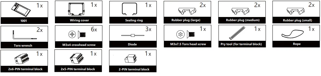
Wall-mounting Accessories (On-Wall Installation Kit box):

Product Overview

Before You Start
Tools needed
(not included in shipped box)
- Cat Ethernet Cable
- Crosshead Screwdriver
- Electric Drill
Voltage and Current Specifications
- 24VDC 1. 5A power adapter to power on device.
- PoE+ (30W)
AWG Sizes and Properties Table
Please follow the properly wire data to install device:
| Power Supply | 24V 1. 5 A | |||||
| AWG | 12 | 14 | 16 | 18 | 20 | |
| Resistance (ohm/km) | 3.51 | 8.45 | 13.5 | 21.4 | 33.9 | |
| Cross-sectional Area (mm²) | 3.332 | 2.075 | 1.318 | 0.8107 | 0.5189 | |
| Length(m) | 24V 1. 5A | ≤40 | ≤30 | ≤20 | ≤10 | ≤5 |
Requirements
- Place the device away from sunlight and light sources to prevent potential damage.
- Do not place the device in the high-temperature, and humid environments or in surroundings impacted by magnetic field.
- Install the device on the flat surface securely to avoid personal injuries and property loss caused by device’s falling.
- Do not use or place the device near heating objects.
- Please keep device at least 2 meters away from light, and at least 3 meters away from window and door.
 Warning!
- To ensure safety, avoid touching power core, power adapter, and device with wet hands, bending or pulling the power core, damaging any components, and use only qualified power adapter and power cord.
- Be careful that standing up on the area under the device in case of personal injuries cause by hitting the device.
Caution
- Do not knock device with hard objects.
- Do not press down hard on the device screen.
- Do not expose device to chemical products, such as alcohol, acid liquid, disinfectants, and so on.
- To prevent the device installation from becoming loose, ensure accurate diameters and depths of screw holes. If the screw holes are too large, use glue to secure the screws.
- Use wet cloth clean device surface softly, and then wipe the surface with dry cloth for cleaning the device.
- If there is abnormal situation of the device, including uncommon sound and smell, please power off the device and contact 1Valet Technical Team immediately.
Wiring Interface

To protect the device from potential damage caused by over-voltage, it is recommended to wire a diode into the circuit. Connect the anode of the diode to the negative cable of the lock, and connect the cathode of the diode to the positive cable of the lock.

Installation
Step1: Bracket Installation
Wall Mounting
- Stick wall-mounting template onto the wall according to your need.
- Please make sure all cables can go through the wiring holes on the template.
 Note: If there is a 86-embedded box installed in the wall, please align the two screw holes of box.
Use a 6mm electric drill to make six holes with 25mm depth in the screw holes of wall-mounting template.
Insert six plastic wall anchors into the holes.
- Use six ST4x20 crosshead screws to fix the wall-mounting box on the wall.
- Or use four ST4x20 crosshead screws and two M4x30 crosshead screws to fix the wall-mounting box on the 86-embedded box.

Step2: Wiring Cover Installation
Hang the device onto the square hanger on the wall-mounting box.
- Choose two rubber plugs of suitable size (small, large and medium).
- Insert one into the back cover of device.
- Insert another into the corresponding groove of the wiring cover.

- Connect the wires to the terminal blocks (for details, refer to “Device Wiring”).
- Insert the terminal blocks into the corresponding interface of the main board.
Note: The pry tool can be used to unplug the terminal block.
- Press sealing ring and wiring cover into the corresponding groove
- Tighten the wiring cover by six M3x4 crosshead screws.

Step 3: Device Mounting
- a. Choose two rubber plugs of suitable size (small, large and medium).
- b. Insert one into the back cover of device.
- c. Insert another into the corresponding groove of the wiring cover.

Note: The protrusion of the box should be covered by the device.
Use torx wrench to screw M3x7.5 Torx head screw into the screw hole on the bottom of device diagonally upward.
Installation is completed, please remove the protective film.
Get Help
For help or more assistance, contact us at: https://1valet.com/
support@1valet.com
FCC Caution
Any Changes or modifications not expressly approved by the party responsible for compl1iance could void the user’s authority to operate the equipment.
This device complies with part 15 of the FCC Rules. Operation 1is subject to the following two conditions:
- This device may not cause harmful interference, and
- This device must accept any 1interference received, induding interference that may cause undesired operation.
Note: T1his equipment has been tested and found to comply with the limits for a Class B digital device, pursuant to part 15 of the FCC Rules.
These imits are designed to provide reasonable protection against harmful interference in a residential 1instaUation. This equipment generates, uses and can radiate radio frequency energy and if not installed and used in accordance ·with the instructions, may cause harmful interference to radio communications. However, there is no guarantee that interference will not occur 11n a particular installation. If this equipment does cause harmful interference to radio or television reception, which can be determined by turnig the equipment off and on, the user is encouraged to try to correct the interference by one or more of the following measures:
- Reorient or relocate the receiv1ing antenna.
- Increase the separation between the equipment and receiver.
- Connect the equipment into an outlet on a circuit different from that to which the receiver is connected.
- Consul the dealer or an exper1ienced radio/TV technician for help.
FCC Radiation Exposure Statement
This equipment complies with FCC radiation exposure llimits set forth for an uncontrolled environment .
This transmitter must not be co – located or operating in conjunction with any other antenna or transmitter.
This equipment should be installed and operated with minimum distance 20cm between the radiator you body.
ISED RSS Warning/ISED RF Exposure Statement
ISED RSS Warning:
This device complies with Innovation, Science and Economic Development Canada licence-exempt RSS standard(s). Operation is subject to the following two conditions:
ISED RF exposure statement
This equipment complies with ISED radiation exposure limits set forth for an uncontrolled environment. This equipment should be installed and operated with minimum distance 20cm between the radiator& your body. This transmitter must not be co-located or operating in conjunction with any other antenna or transmitter.
FAQ
Question: What should I do if I encounter an abnormal situation with the device?
Answer: If you experience any uncommon sounds or smells from the device, power it off immediately and contact 1Valet Technical Team for assistance.
Documents / Resources
 | 1VALET 1001 Smart Intercom Console [pdf] User Guide 1001, 1001 Smart Intercom Console, Smart Intercom Console, Intercom Console, Console |


