Waveshare RP2350-Tiny
Waveshare RP2350-Tiny 마이크로컨트롤러 개발 보드 키트 사용 설명서
Model: RP2350-Tiny
1. 서론
This manual provides detailed instructions for the Waveshare RP2350-Tiny Microcontroller Development Board Kit. It covers the board's features, specifications, setup procedures, operation guidelines, and troubleshooting tips to help users effectively utilize the development board.
The RP2350-Tiny is a compact development board based on the Raspberry Pi RP2350A microcontroller. It features a unique dual-core and dual-architecture design, integrating an Arm Cortex-M33 processor and a Hazard 3 RISC-V processor, capable of flexible clock speeds up to 150 MHz. This kit is designed for various embedded applications and supports C/C++ and MicroPython programming.
2. 패키지 내용
아래 나열된 모든 품목이 패키지에 포함되어 있는지 확인하세요.
- RP2350-Tiny Development Board x1
- USB Port Adapter x1
- FPC Cable (~15cm) x1

Image: The RP2350-Tiny development board connected via an FPC cable to the USB port adapter, illustrating the main components of the kit.
3. 주요 특징
The Waveshare RP2350-Tiny Development Board offers the following key features:
- 마이크로 컨트롤러 : Raspberry Pi RP2350A chip with dual-core Arm Cortex-M33 and dual-core Hazard 3 RISC-V processors.
- 클럭 속도: Flexible clock running up to 150 MHz.
- 메모리: 520KB Static Random-Access Memory (SRAM) and 4MB on-board Flash memory.
- 연결성: Onboard FPC 8-PIN connector, adaptable to USB Type-C via adapter board.
- 폼 팩터: Castellated module design for direct soldering to carrier boards.
- USB: 장치 및 호스트를 지원하는 USB 1.1.
- 전원 모드: 저전력 절전 및 대기 모드.
- 프로그램 작성: Drag-and-drop programming via mass storage over USB.
- GPIO: 28개의 다기능 GPIO 핀(20개는 엣지 핀아웃 방식, 나머지는 솔더 포인트 방식).
- 주변 장치: 2 SPI, 2 I2C, 2 UART, 4 12-bit ADC, 16 controllable PWM channels.
- PIO: 12 Programmable I/O (PIO) state machines for custom peripheral support.
- 추가의: Accurate clock and timer, on-chip temperature sensor, accelerated floating-point libraries.

이미지: 오버view of the RP2350-Tiny Development Board highlighting its key features such as tiny size, dual-core architecture, high operating performance, and multi-function GPIO pins.
4. 기술 사양
| 특징 | 사양 |
|---|---|
| 마이크로 컨트롤러 | Raspberry Pi RP2350A (Dual-core Arm Cortex-M33, Dual-core Hazard 3 RISC-V) |
| 클럭 속도 | 최대 150MHz |
| 에스램 | 520킬로바이트 |
| 플래시 메모리 | 4 MB (on-board) |
| USB | USB 1.1 (장치 및 호스트 지원) |
| GPIO 핀 | 28 multi-function (20 via edge pinout) |
| 주변기기 | 2 SPI, 2 I2C, 2 UART, 4 12-bit ADC, 16 PWM channels |
| PIO 상태 머신 | 12 |
| Dimensions (RP2350-Tiny) | 0.92 x 0.7 x 0.39인치(약 23.5 x 18 x 10mm) |
| 무게 | 0.16 온스(약 4.5그램) |
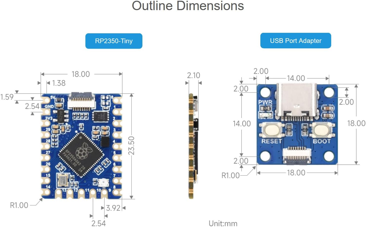
Image: Detailed outline dimensions for both the RP2350-Tiny development board and the USB Port Adapter, shown in millimeters.
5. 보드 레이아웃 및 구성 요소
Understanding the layout of the RP2350-Tiny board is crucial for proper usage. The following diagram identifies key components:

이미지: 위에서 아래로 view of the RP2350-Tiny board with numbered callouts identifying major components such as the FPC connector, voltage regulator, Flash memory, RP2350A chip, and RGB LED indicator.
- FPC connector: 0.5mm pitch 8PIN connector for external connections, typically to the USB adapter.
- ME6217C33M5G: Low dropout regulator, providing up to 800mA output (Max.).
- P25Q32SH-UXH-IR: 4MB NOR-Flash memory for program storage.
- RP2350A: The main dual-core, dual-architecture microcontroller chip.
- WS2812: RGB LED indicator for visual feedback.
GPIO Pinout
The RP2350-Tiny features 28 multi-function GPIO pins. The pinout diagram below illustrates the available pins and their primary functions.
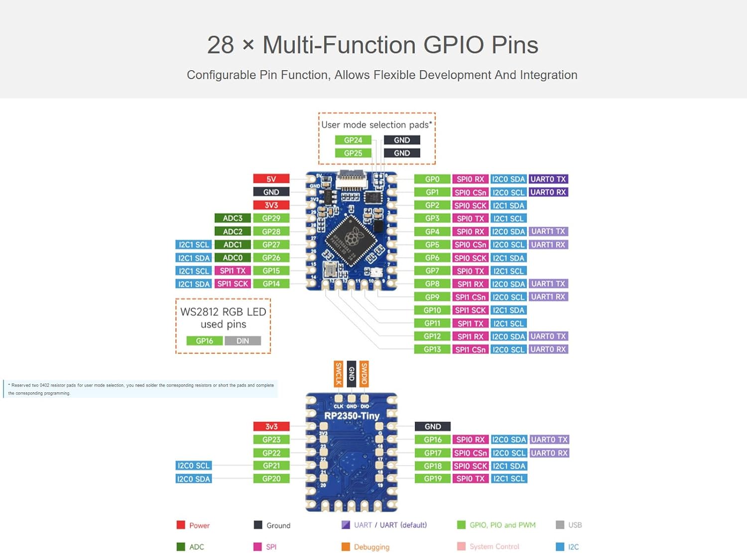
Image: A detailed diagram showing the GPIO pinout of the RP2350-Tiny board, including power, ground, UART, SPI, I2C, ADC, and PWM functions, along with user mode selection pads.
6. 설정 지침
6.1 Connecting the USB Port Adapter
The RP2350-Tiny development board connects to a host computer via the provided USB Port Adapter and FPC cable.
- Carefully connect one end of the FPC cable to the 8-PIN FPC connector on the RP2350-Tiny board. Ensure the cable is inserted correctly with the contacts facing the appropriate direction.
- Connect the other end of the FPC cable to the corresponding 8-PIN FPC connector on the USB Port Adapter.
- Plug the USB Type-C end of the USB Port Adapter into your computer.
Upon successful connection, the board should be recognized by your computer, typically as a mass storage device for drag-and-drop programming.
6.2 소프트웨어 환경 설정
To develop applications for the RP2350-Tiny, you will need to set up a development environment. The board supports C/C++ and MicroPython.
- For C/C++ Development: Utilize the Pico C/C++ SDK. This SDK can be used from the command line or integrated with popular development environments like Visual Studio Code and Eclipse. Refer to the official Raspberry Pi Pico documentation for detailed setup instructions.
- For MicroPython Development: MicroPython is a full implementation of the Python 3 programming language optimized for embedded hardware. You can flash a MicroPython firmware to the board and then use a serial terminal or an IDE like Thonny for programming.

Image: An illustration showing the support for C/C++ SDK and MicroPython development environments for the RP2350-Tiny board.
7. Operating the RP2350-Tiny
7.1 Programming via USB (Drag-and-Drop)
The RP2350-Tiny supports drag-and-drop programming, which is a convenient way to upload firmware or MicroPython scripts.
- With the board connected to your computer via the USB Port Adapter, press and hold the BOOTSEL button on the USB Port Adapter while plugging it into your computer (or press BOOTSEL and then RESET if already connected).
- The board will appear as a mass storage device (e.g., "RPI-RP2").
- Drag and drop your compiled firmware (.uf2 file for C/C++ or .py file for MicroPython) onto this drive.
- The board will automatically reboot and run the new program.
7.2 GPIO Usage
The 28 multi-function GPIO pins can be configured for various purposes, including digital input/output, analog input (ADC), serial communication (SPI, I2C, UART), and Pulse Width Modulation (PWM).
- Refer to the GPIO pinout diagram in Section 5 for pin assignments.
- When programming, ensure that the correct pin numbers and functions are specified in your code.
- Be mindful of voltage levels; the RP2350-Tiny operates at 3.3V logic.
7.3 전원 관리
The RP2350-Tiny supports low-power sleep and dormant modes to conserve energy in battery-powered applications. Consult the RP2350A datasheet and SDK documentation for details on implementing these power-saving features in your code.
8. 유지관리 및 관리
- 손질: 개발 보드를 다룰 때는 항상 가장자리를 잡고 다루어 부품, 특히 정전기 방전(ESD)에 민감한 핀에 손이 닿지 않도록 하십시오.
- 저장: Store the board in an anti-static bag when not in use, in a cool, dry environment.
- 청소: 필요한 경우 부드럽고 마른 브러시나 압축 공기를 사용하여 도마를 살살 닦아주세요. 액체나 연마성 재료는 사용하지 마세요.
- 전원 공급 장치: Ensure a stable 5V power supply when connecting via USB. Over-voltag보드가 손상될 수 있습니다.
9. 문제 해결
- 컴퓨터에서 보드를 인식하지 못합니다.
- Ensure the FPC cable is securely connected to both the RP2350-Tiny and the USB Port Adapter.
- 다른 USB 케이블을 사용하거나 컴퓨터의 USB 포트에 연결해 보세요.
- Verify that you are holding the BOOTSEL button while connecting the USB adapter to enter mass storage mode.
- Program not running after upload:
- Confirm that the correct .uf2 or .py file was dragged to the "RPI-RP2" drive.
- Check your code for errors.
- Ensure the board automatically rebooted after the file transfer. If not, manually reset the board.
- Peripherals (e.g., I2C, SPI) not working:
- Double-check your wiring against the GPIO pinout diagram.
- Verify that the correct GPIO pins are initialized and configured in your software.
- Ensure external components are properly powered and connected.
- 보드가 뜨거워집니다:
- Disconnect power immediately.
- Check for short circuits on the board or in your external connections.
- 입력 볼륨을 확인하세요tage is within the specified range (5V via USB).
10. 기술 지원 및 자료
For further assistance, online development resources, and technical support, please refer to the Waveshare official website or contact their support team. Detailed documentation, examples, and community forums are often available to help with advanced projects and specific issues.
추가 자료 및 연락처 정보는 다음에서 확인하실 수 있습니다. 아마존에서 Waveshare 스토어를 만나보세요.
관련 문서 - RP2350-Tiny
 |
Waveshare ESP32-S3-Touch-LCD-4.3 개발 보드: 기능 및 가이드 4.3인치 정전식 터치 디스플레이, WiFi, BLE 5, 그리고 CAN, RS485, I2C 등 다양한 인터페이스를 갖춘 강력한 마이크로컨트롤러 개발 보드, Waveshare ESP32-S3-Touch-LCD-4.3을 살펴보세요. 하드웨어, 설정 및 기능에 대해 알아보세요.ampHMI 개발을 위한 데모. |
 |
라즈베리파이 피코 듀얼모드 블루투스 모듈(Pico-BLE) 사용 설명서 Waveshare Pico-BLE 사용 설명서입니다. Raspberry Pi Pico용으로 설계된 듀얼 모드 Bluetooth 5.1 모듈로, SPP 및 BLE 프로토콜을 지원합니다. 헤더 호환성과 온보드 안테나를 갖추고 있습니다. |
 |
Open103R User Manual User manual for the Waveshare Open103R STM32F103RCT6 development board, including hardware overview, component details, and demo setup instructions. |
 |
Open746I-C Package B Development Board User Guide Technical specifications and user guide for the Waveshare Open746I-C Package B development board featuring the STM32F746IGT6 microcontroller. |
 |
EVK407I Development Board User Manual Comprehensive user manual for the Waveshare EVK407I development board, covering hardware specifications, component layout, and software demonstration guides for the STM32F407IGT6 microcontroller. |
 |
ESP32-S3-Touch-LCD-2 Development Board Guide A comprehensive guide for the Waveshare ESP32-S3-Touch-LCD-2 development board, covering setup and usage with Arduino IDE and ESP-IDF, including detailed examp파일 및 리소스. |
Ask a question about this manual
Ask about setup, troubleshooting, compatibility, parts, safety, or missing instructions. Manuals+ will review the question and use this page’s manual context to help answer it.